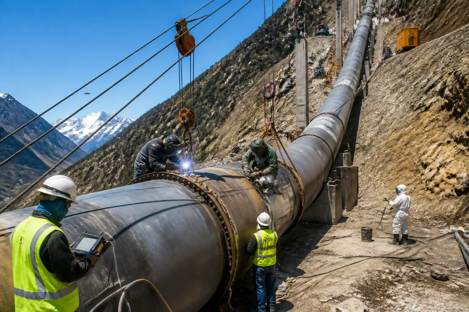

Method Statement: Penstock Pipe Installation, Welding, Coating, and Hydrostatic Testing – Method Statement
AI-assisted method statement with matching ITP, PDF download, and Excel export.
More than a static template
Unlike a downloadable Word or PDF template, this method statement is an AI-assisted editable starting point connected directly to a matching Inspection and Test Plan. Every section is structured, project-adaptable, and ready to export.
- AI-assisted drafting — Customize every section with AI for your specific project scope.
- Linked ITP — A matching inspection and test plan is generated alongside the method statement.
- Multiple export formats — Download as a formatted PDF or editable Excel spreadsheet.
- Editable starting point, not a final document — Review, verify, and adjust all content against your project requirements before use.
Static template vs. Quollnet workflow
| Feature | Static template | Quollnet |
|---|---|---|
| Project-specific content | Manual fill-in required | AI-assisted customization |
| Linked ITP | Separate document, no link | Matching ITP included |
| Export formats | Usually PDF only | PDF and Excel |
| Structured sections | Free-form layout | 13 standardized sections |
| Saved to your account | Local file only | Cloud-saved, reusable |
| Content accuracy | You verify everything | AI-assisted, you still verify |
| Cost | Often free but time-intensive | Free to customize and download |
What you can customize
When you save this method statement to your account, every section becomes editable. The following 13 sections are included:
- Scope — Defines the activity and its boundaries.
- References — Standards, specifications, and drawings.
- Responsibilities — Roles and accountabilities.
- Resources — Labour, plant, and equipment summary.
- Materials — Materials and compliance requirements.
- Equipment — Tools and equipment details.
- Prerequisites — Hold points and pre-conditions.
- Method sequence — Step-by-step construction sequence.
- Safety controls — HSE risk controls and PPE.
- Environmental controls — Environmental mitigation measures.
- QA/QC — Quality inspection and test requirements.
- ITP — Inspection and Test Plan table (has its own page).
- Attachments — Referenced drawings and documentation.
Why this method statement is used
This method statement is used to define and communicate the approved procedure for carrying out method statement: penstock pipe installation, welding, coating, and hydrostatic testing on site. It ensures the work is planned in advance, the correct resources and controls are in place, and all personnel understand responsibilities, sequence, quality requirements, and safety controls before work begins. It aligns site execution with the documented scope and acceptance expectations.
Who uses this method statement
This method statement is used by contractors, site supervisors, project engineers, QA/QC engineers, HSE officers, consultants, and client representatives. It serves as a shared reference for planning, execution, supervision, inspection, and approval of the activity on site.
When it is prepared and submitted
The method statement is prepared before the work activity starts and submitted as part of the pre-construction documentation package for review and approval.
Who reviews or approves it
The method statement is usually submitted to the client representative, consultant, resident engineer, or project management consultant for review and approval before the work commences.
Important approval note
This method statement is an AI-assisted editable starting point, not a pre-approved document. Before use on any project, all content must be reviewed and approved by the relevant parties (superintendent, principal contractor, or client representative) in accordance with your contract and project quality plan.
For example: if your specification requires a departure from a referenced standard, that departure must be documented and approved separately — this method statement will not capture that automatically. Always verify against your applicable drawings, specifications, and regulatory requirements.
Method statement content
Scope
Work Summary
- Install, align, weld, NDT examine, coat, and hydrostatically test steel penstock pipes and appurtenances (bends, reducers, manholes, nozzles) along steep slopes and in power/intake houses.
- Include temporary works and specialized rigging on slopes, survey and setting-out, fit-up and internal/external line-up, welding (SMAW/GMAW/FCAW/SAW where applicable), 100% volumetric NDT of circumferential welds, surface NDT, blasting and protective coating, holiday detection, hydrostatic testing, drying, and reinstatement.
- Excludes permanent civil structures beyond pipe supports unless noted.
Deliverables
- Installed, tested, and coated penstock sections to approved alignment and levels, with full quality records: weld maps, NDT reports, coating inspections, hydrotest dossier, as-built drawings.
Locations
- Steep slope penstock route from intake/forebay to powerhouse; valve chambers; bifurcation zones; anchor blocks; aboveground/embedded sections as shown on IFC drawings.
Key Performance Requirements [Verify per project specifications]
- Alignment tolerance at girth joint: ±5 mm in plan/elevation over 10 m; joint hi–lo (internal mismatch): ≤10% of wall thickness, max 3 mm.
- Root gap: 2–4 mm typical; bevel angle 30–37.5°.
- Preheat per WPS based on carbon equivalent (typ. 75–150°C); interpass ≤250°C unless WPS states otherwise.
- 100% volumetric NDT of circumferential welds (UT/AUT, or RT where access permits). Acceptance: ISO 5817 Level B or ISO 11666 Level 2 (or project spec).
- Blast cleanliness: ISO 8501-1 Sa 2½; surface profile 50–100 µm; soluble salts ≤20 mg/m² (Bresle) before coating.
- Coating system DFT: 300–600 µm total (per manufacturer); holidays: zero; repair all detected.
- Hydrostatic test: 1.25 × design pressure; strength hold ≥2 h; leak test 8–24 h. No visible leaks; stabilized pressure loss within instrument tolerance after temperature correction.
- Environmental and HSE controls implemented and verified.
References
| Document Type | Reference / Number | Revision | Notes |
|---|---|---|---|
| Code/Standard | ASME B31.1 | ||
| Code/Standard | EN 13480 | ||
| ISO/ASME | ISO 15614-1; ISO 9606-1; ASME Section IX (as applicable) | Use one route consistently per project spec. | |
| ISO | ISO 5817; ISO 17635; ISO 17640 (UT); ISO 17636-1 (RT); ISO 17638 (MT); ISO 23277 (MT acceptance); ISO 11666 (UT acceptance) | Select method/acceptance per project spec. | |
| ISO | ISO 13916 | ||
| ISO/NACE/SSPC/AWWA | ISO 8501-1; ISO 8502-4; ISO 8503; ISO 12944; ISO 19840; NACE SP0188; SSPC-PA 2; AWWA C210/C222 (if applicable) | Select coating standard/system per manufacturer TDS and project spec. | |
| ISO | ISO 9001 (QMS) | ||
| ISO/BS/Local | ISO 45001; ISO 14001; BS 5975 (Temporary Works); Local lifting/rigging regulations [Verify per project HSE plan and local regulations] |
Responsibilities
| Role | Responsibility | Name / Party |
|---|---|---|
| PM | Approve method/ITP, ensure resources and permits. | Contractor |
| CM | Lead coordination, enforce HSE, approve daily work fronts. | Contractor |
| SE | Check alignments, elevations, fit-up tolerances. | Contractor |
| WE | Qualify and monitor welding; resolve NCRs. | Contractor |
| QA/QC | Manage inspections, records, handover dossier. | Contractor |
| CI | Verify DFT, profile, salts, cure. | Contractor/Inspector |
| NDT | Ensure 100% volumetric NDT; supervise technicians. | Approved NDT Agency |
| Rigging | Verify anchors, WLL, exclusion zones. | Contractor |
| Survey | Issue as-set and as-built coordinates. | Contractor |
| HSE | Enforce HSE plan, conduct toolbox talks, incident reporting. | Contractor |
| Test | Conduct test and acceptance per ITP. | Contractor |
Resources
| Resource Type | Description | Quantity | Remarks |
|---|---|---|---|
| Manpower | SMAW/FCAW/GMAW/SAW as per WPS | 8–16 [Verify per project] | |
| Manpower | Slope hauling and positioning | 8–12 | |
| Manpower | Line-up, clamps, tacking | 6–10 | |
| Manpower | Blasting and coating | 6–12 | |
| Manpower | UT/RT/MT/PT | 3–6 | |
| Manpower | Pumps, manifolds, vent/drain ops | 4–6 |
Materials
| Material | Specification / Grade | Quantity | Remarks |
|---|---|---|---|
| Carbon steel | EN 10025/ASTM A572 | As per BOQ | |
| Welding consumables | AWS A5.xx / ISO 2560/14341/17632 | Per weld plan | |
| Industrial coatings | Per manufacturer | Per drawings | |
| Abrasive | ISO 11126/11127 | As required | |
| Chemicals | Local permit [Verify] | As needed |
Equipment
| Equipment | Capacity / Type | Quantity | Inspection Required |
|---|---|---|---|
| Winches 5–20 t; ropes per calc | As designed | As per plan | |
| Clamps | 2–4 sets | ||
| Weld sets; preheat units | As required | ||
| UT/PAUT, RT, MT | As required | ||
| Blasters, sprayers | Sets as required | ||
| Test skid | Pressure ≥1.5 × test P | 1 set |
Prerequisites
Documentation and Approvals
- IFC drawings, valve/branch details, and survey control benchmarks issued.
- Approved Method Statement and ITP; Risk Assessments/Job Hazard Analyses; Lift/Rigging Plans; Temporary Works Design and permits; interface permits from other disciplines.
- Approved WPS/PQR; welder qualifications (ISO 9606-1 or ASME IX); NDT procedures; coating manufacturer approvals.
- Material test reports (MTRs), coating TDS/SDS, consumable certificates.
Site Readiness
- Access roads/tracks established; slope work platforms/rope access lines installed and inspected.
- Foundations/anchor blocks ready and surveyed; temporary saddles/rollers installed.
- Power, compressed air, lighting, ventilation (for internal work) available. Fire extinguishers placed.
Calibration and Verification
- Calibrations current for welding sets, NDT equipment, DFT gauges, hygrometers, pressure gauges, load cells.
- Weather criteria for coating: RH ≤85%, steel temperature ≥3°C above dew point, ambient ≥10°C (or per TDS). Wind shields for blasting/coating on slopes.
HSE and PTWs
- Inductions, toolbox talks, emergency/rescue plan for steep slopes and confined space entries approved.
- PTWs issued: Hot Work, Confined Space, Lifting, Radiography (if RT), Excavation (if any), Hydrotest.
Materials and Logistics
- Pipes inspected for transport damage; ends beveled and protected; internal cleanliness checked.
- Consumables baked and stored (E7018 at 250–350°C; holding ovens 100–150°C) [Verify per manufacturer].
Constraints/Controls [Verify per project specifications]
- Weather limits for suspended loads: stop at sustained wind ≥10 m/s or gusts ≥12 m/s.
- Slope-specific anchor capacities proven by pull test or design verification.
- Work sequencing coordinated to avoid coating damage before hydrotest; plan for touch-up after testing.
Method Sequence
| Step | Activity | Description | Responsibility | Inspection / Hold Point |
|---|---|---|---|---|
| 1 | Survey and Setting Out | Establish and verify control points; set centerline, elevations, and rotational marks along slope; issue as-set report. | Surveyor / Site Engineer | Independent check of control |
| 2 | Temporary Works & Rigging Installation | Install anchors, winches, wire ropes, and rollers/saddles per Temporary Works Design; establish exclusion zones and rescue plan. | Rigging Supervisor / TWC | Pre-use thorough examinations |
| 3 | Receipt and Inspection of Pipe & Materials | Unload with spreader bars; check MTRs; inspect bevels and end preps; mark heat numbers; protect internal surfaces. | QA/QC / Storekeeper | Visual, dimensional |
| 4 | Section Hauling and Positioning on Slope | Haul pipe with winches/rollers; maintain taglines; position at joint; secure with chocks and secondary restraints. | Rigging Supervisor | Rigging checks |
| 5 | Fit-up and Alignment | Clean bevels to bright metal; install line-up clamps; set root gap 2–4 mm; control hi–lo; confirm land thickness and bevel quality; verify internal cleanliness. | Site Engineer / Fitter / QC | Visual and dimensional |
| 6 | Preheat and Tack Welding | Apply preheat per WPS (typ. 75–150°C based on CE and thickness); tacks 25–50 mm every 150–250 mm; grind/MT tacks if left in joint. | Welding Engineer / Welder | Temperature verification |
| 7 | Root Pass Welding | Weld root pass with qualified process (SMAW/GMAW/FCAW). Control heat input and interpass; ensure full penetration; backgouge if double-sided. | Welder / Welding Engineer | In-process welding surveillance |
| 8 | Root Pass NDT (Surface) | After cleaning, perform MT on root/accessible side (or PT if suitable) especially at tie-ins and stops/starts. | NDT Level II / QC | MT/PT |
| 9 | Filling and Cover Passes | Deposit subsequent passes maintaining interpass ≤250°C (unless WPS states otherwise); clean and VT each pass; control weave width per WPS; avoid arc strikes. | Welder / QC | VT between passes |
| 10 | Final Visual Inspection of Weld | Clean weld; check reinforcement, undercut, overlap, and contour; mark weld ID and welder stamps. | QC Inspector | VT |
| 11 | Volumetric NDT – 100% | Perform UT/PAUT (preferred on slopes) or RT if access allows. Observe delayed hydrogen indications by waiting ≥24 h after weld completion for high-CE steels [Verify]. | NDT Level II/III | UT/PAUT/RT |
| 12 | Weld Repairs (if any) and Re-examination | Excavate defects by grinding/gouging; re-weld per WPS; re-NDT affected area 100%. Limit repairs per WPS/Code. | Welding Engineer / Welder / NDT | VT + UT/RT/MT as required |
| 13 | Surface Preparation for Coating | Mask welds/areas as needed; blast to Sa 2½; verify profile 50–100 µm; salts ≤20 mg/m²; clean to dust grade acceptable per TDS. | Coating Team / CI | Surface inspection |
| 14 | Coating Application and Inspection | Apply primers/intermediate/topcoats per TDS; monitor RH/dew point; measure WFT/DFT; stripe coat edges/crevices; cure per TDS. | Coating Applicators / CI | Coating QC |
| 15 | Holiday Detection and Repairs | After cure, holiday test at voltage per NACE SP0188 based on DFT; repair all defects; re-test until no holidays. | CI / QA/QC | Holiday test |
| 16 | Installation of Test Heads and Instrumentation | Install blinds/test heads, calibrated gauges (class ≥0.6), relief valves; fit vents at high points and drains at low points; verify supports and anchors. | Hydrotest Engineer / SE | Pre-test checklist |
| 17 | Filling, Venting, and Stabilization | Fill from low point at controlled rate; vent all high points until air-free; soak to equalize temperature; check for leaks at ambient pressure. | Hydrotest Crew / HSE | Visual leak check |
| 18 | Hydrostatic Strength Test | Raise pressure to 1.25 × design pressure; hold ≥2 h; monitor pressure/temperature; inspect welds and supports. | Hydrotest Engineer / QA/QC / Client | Pressure monitoring |
| 19 | Leak Test (Extended) | Reduce to leak test pressure (e.g., design pressure) and hold 8–24 h [Verify]; inspect all joints; document readings. | Hydrotest Engineer / QA/QC | Leak patrols |
| 20 | Depressurization, Draining, and Drying | Controlled depressurization via manifolds; drain to approved points; dry by air blowers/desiccant until dew point criteria met (if required). | Hydrotest Crew / Environmental Officer | Discharge monitoring |
| 21 | Post-Test Coating Touch-ups and Finalization | Repair any coating damage; DFT and holiday re-check at repairs; install permanent appurtenances; remove temporary works. | Coating Team / CM | Coating QC |
| 22 | As-Built and Handover | Compile weld/NDT maps, coating dossiers, hydrotest certificates, calibration, and as-built drawings; close NCRs/Snags. | QA/QC Manager | Document review |
Health, Safety, and Environment – Safety Controls
Principal Task-Specific Hazards and Controls
1) Hazard: Uncontrolled pipe movement on steep slope (rigging/anchor failure)
- Likely consequence: Crush injuries, fatalities, structural damage.
- Engineering/procedural control: Engineered anchors and rigging per Temporary Works Design; WLL ≥1.5–2.0 × load; dual independent restraints; load path analysis; exclusion zones; taglines; winch brakes and backup secondary capture line; stop work at wind ≥10 m/s sustained. [Verify per project HSE plan and local regulations]
- Required PPE: Helmet with chinstrap, cut-resistant gloves, safety boots, high-vis, eye protection.
- Collective preventive measure: Physical barriers and banksmen to enforce exclusion; edge protection where feasible; rescue plan and equipment staged.
- Inspection/permit/supervision: Pre-use/weekly rigging inspections; Lifting PTW; Appointed Person and Rigging Supervisor present.
2) Hazard: Working at height on steep terrain
- Likely consequence: Falls, severe injury.
- Engineering/procedural control: Certified fall protection systems; rope access with twin lanyards; fixed lifelines; properly rated anchors; work positioning harnesses; maintained 3 points of contact.
- Required PPE: Full-body harness with double lanyards, fall arrest device, anti-slip boots, helmet with chinstrap.
- Collective measure: Temporary walkways/steps with anti-slip mats; guard lines; rescue kit and trained standby.
- Inspection/permit/supervision: Working at Height PTW; daily equipment checks; supervisor oversight.
3) Hazard: Hot work (welding, cutting, grinding)
- Likely consequence: Burns, fires, eye injury.
- Engineering/procedural control: Hot Work PTW; fire blankets/screens; fire watch with extinguishers (ABC/CO2); segregate flammables; maintain preheat with controlled sources; grinding spark containment.
- PPE: FR clothing, welding hood/face shield, gloves (welding/heat rated), safety glasses, hearing protection.
- Collective measure: Fire watch during and 30 min after; dedicated hot work zone.
- Inspection/permit/supervision: Gas hose checks, flashback arrestors; calibrated welding sets; Hot Work PTW.
4) Hazard: Confined space inside pipe
- Likely consequence: Asphyxiation, toxic exposure, entrapment.
- Engineering/procedural control: Confined Space PTW; atmospheric testing (O2, CO, H2S, CO2) continuous or periodic; forced ventilation; limited entry points with attendant and rescue plan; lighting 24 V.
- PPE: Gas monitor, harness, retrieval line, FR clothing, gloves, head/eye protection.
- Collective measure: Barriers and signage at entries; standby rescue team.
- Inspection/permit/supervision: Entry log, gas readings recorded, rescue drill readiness.
5) Hazard: Radiography (if used)
- Likely consequence: Radiation exposure.
- Engineering/procedural control: Prefer UT/PAUT; if RT, controlled area with cordons and warning lights; time–distance–shielding principles; qualified RSO.
- PPE: Dosimeters, RT signage; specific PPE as required by procedure.
- Collective measure: Evacuate exclusion zone during exposure; interlocks/timers.
- Inspection/permit/supervision: Radiography PTW; regulatory notifications; RSO oversight.
6) Hazard: Manual handling of heavy clamps and equipment
- Likely consequence: Musculoskeletal injury, crush points.
- Engineering/procedural control: Use mechanical aids, team lifts, lift plans for heavy items, pinch point guards.
- PPE: Gloves, boots, eye protection.
- Collective measure: Pre-task briefings; clear laydown area.
- Inspection/permit/supervision: Supervisor checks; tool inspections.
7) Hazard: Hydrostatic test stored energy release
- Likely consequence: Pipe rupture, projectile hazards, flooding.
- Engineering/procedural control: Test head design verified; calibrated gauges; staged pressurization; barricades; no personnel in line-of-fire; relief valves set slightly above test pressure; gradual depressurization.
- PPE: Helmets, eye protection, hearing protection.
- Collective measure: Exclusion zones and remote monitoring.
- Inspection/permit/supervision: Hydrotest PTW; Engineer approval of test plan; continuous supervision.
8) Hazard: Noise and vibration (grinding, blasting)
- Likely consequence: Hearing loss, vibration injury.
- Engineering/procedural control: Low-noise equipment, time limits, job rotation.
- PPE: Hearing protection (SNR adequate), anti-vibration gloves.
- Collective measure: Noise barriers on slope where practical.
- Inspection/permit/supervision: Noise monitoring records.
9) Hazard: Fumes and dust (welding, blasting, coating)
- Likely consequence: Respiratory irritation or illness.
- Engineering/procedural control: Local exhaust/ventilation; capture blasting dust; select low-VOC coatings; no spraying in high winds.
- PPE: Respirators (P3/OV cartridges as applicable), goggles.
- Collective measure: Enclosures and dust collectors.
- Inspection/permit/supervision: Air monitoring as required; SDS available.
Environmental Controls
Key Environmental Aspects and Controls
- Erosion and sediment on steep slopes
- Impact: Sediment-laden runoff to watercourses.
- Control: Silt fences, berms, fiber rolls; staged works; immediate stabilization with mats/seed; spillways for concentrated flows.
-
Monitoring: Daily checks after rain; maintain logs. [Verify per project environmental plan]
-
Abrasive blasting waste and dust
- Impact: Contamination with paint residues and heavy metals.
- Control: Containment tarps; vacuum recovery; classify waste; dispose via licensed facility; maintain negative pressure where enclosed.
-
Monitoring: Visual dust checks; waste transfer notes.
-
Coating VOCs and odors
- Impact: Air quality, worker/community exposure.
- Control: Low-VOC products where possible; mixing in ventilated areas; no spraying above wind limits; adhere to TDS cure times to prevent solvent entrapment.
-
Monitoring: Solvent inventory; odor complaints log.
-
Hydrotest water discharge
- Impact: Thermal/chemical shock to receiving waters; erosion at outlets.
- Control: Sample water (pH, turbidity/TSS, residual biocide); neutralize if needed; energy dissipation at discharge; discharge to approved points per permit.
-
Monitoring: Water quality results; flow rate control records.
-
Fuel/chemical storage on slopes
- Impact: Soil/water contamination.
- Control: Double-bunded storage; drip trays; spill kits; refuel at designated pads with absorbents; trained personnel only.
-
Monitoring: Weekly inspections; spill register.
-
Noise to nearby receptors/wildlife
- Impact: Nuisance and ecological disturbance.
- Control: Time restrictions; mufflers; acoustic screens; notify stakeholders for high-noise activities.
-
Monitoring: Spot measurements; complaint tracking.
-
Waste management
- Impact: Littering and mixed waste.
- Control: Segregate metal offcuts, abrasive waste, coating tins; recycle metals; remove daily from slope.
- Monitoring: Waste logs and tickets.
Quality Assurance / Quality Control
QA/QC Regime
- Document Control: Use approved IFC drawings, WPS/PQR, coating TDS, NDT procedures. Maintain revision control.
- Material Control: Verify MTRs, heat numbers, and traceability; weld map linking heats, filler batches, and welders.
- Equipment Calibration: Maintain current calibration for weld sets, pyrometers, DFT gauges, UT sets, pressure gauges, load cells; keep certificates in test packs.
- Welding Quality Control:
- Fit-up inspection and Hi–Lo/Gap verification prior to welding (H). Record in ITP.
- Preheat/interpass monitoring logs per ISO 13916.
- In-process VT each pass; MT on root/tacks as specified.
- 100% volumetric NDT of circumferential welds (UT/PAUT preferred). Acceptance to ISO 11666 Level 2 or project requirement; visual quality to ISO 5817 Level B unless specified otherwise.
- Repair control: RPRs, excavation dimensional checks, re-NDT 100% of repaired zones.
- Coating Quality Control:
- Environmental conditions recorded each shift (RH, steel temp, dew point).
- Surface prep checks: Sa 2½, profile 50–100 µm, salts ≤20 mg/m².
- DFT/WFT, holidays zero; adhesion if specified.
- Hydrotest Quality Control:
- Approved test procedure; calibrated instruments; temperature-compensated acceptance; leak log and patrol sheets; as-left status verified (vents/drains closed, test heads removed).
- Records and Handover: As-built survey, weld/NDT map, consumable control logs, coating QC pack, hydrotest dossier, calibration certs, PTWs, HSE records, NCR/CAR closeout.
H = Hold point; W = Witness point (refer to ITP).
Attachments
- Approved IFC drawings (plan, profile, details, sections)
- WPS/PQR packages; Welder qualification records (WQTR)
- NDT procedures and personnel certifications; technique sheets
- Temporary Works Design calculations and drawings; rigging plan
- Lift plans, equipment certificates, and inspection reports
- Coating system TDS/SDS; coating QC forms and calibration certificates
- Preheat/interpass temperature logs; weld maps and repair logs
- Hydrotest procedure, pressure test certificates, gauge calibrations
- HSE documents: RA/JHA, PTWs, emergency and rescue plans
- Environmental permits and water discharge approvals
- Manufacturer manuals/datasheets for equipment
- As-built survey and final handover dossier
This content is a read-only public reference. Download or customize to get an editable version.
ITP preview
The first inspection activities from the linked ITP for Method Statement: Penstock Pipe Installation, Welding, Coating, and Hydrostatic Testing:
| Activity | Inspection / Test | Acceptance Criteria | Responsibility | Record |
|---|---|---|---|---|
| Survey and setting out | Verify control points, alignment and elevation checks | Within specified tolerances (±5 mm over 10 m) [Verify] | Surveyor / QC / Client | Survey report, ITP checklist |
| Incoming material verification | MTR review, dimensional/visual inspection | Compliant with material spec and drawings | QA/QC | Receiving inspection, MTR log |
| Rigging and temporary works pre-use | Certificates, visual checks, anchor verification | Per Temporary Works Design; valid certifications | Rigging Supervisor / QA/QC | Rigging checklists, certificates |
Showing 3 of 16 inspection activities. View full ITP →
Related Inspection and Test Plan
An Inspection and Test Plan (ITP) is available for Method Statement: Penstock Pipe Installation, Welding, Coating, and Hydrostatic Testing. The ITP defines the inspection activities, acceptance criteria, hold and witness points, responsible parties, and records required to verify the work described in this method statement.
View the Method Statement: Penstock Pipe Installation, Welding, Coating, and Hydrostatic Testing ITP →