
Method Statement for Hot Tapping Tie-In Connections on Live Pressurized Chilled Water (CHW) Piping – Method Statement
AI-assisted method statement with matching ITP, PDF download, and Excel export.
More than a static template
Unlike a downloadable Word or PDF template, this method statement is an AI-assisted editable starting point connected directly to a matching Inspection and Test Plan. Every section is structured, project-adaptable, and ready to export.
- AI-assisted drafting — Customize every section with AI for your specific project scope.
- Linked ITP — A matching inspection and test plan is generated alongside the method statement.
- Multiple export formats — Download as a formatted PDF or editable Excel spreadsheet.
- Editable starting point, not a final document — Review, verify, and adjust all content against your project requirements before use.
Static template vs. Quollnet workflow
| Feature | Static template | Quollnet |
|---|---|---|
| Project-specific content | Manual fill-in required | AI-assisted customization |
| Linked ITP | Separate document, no link | Matching ITP included |
| Export formats | Usually PDF only | PDF and Excel |
| Structured sections | Free-form layout | 13 standardized sections |
| Saved to your account | Local file only | Cloud-saved, reusable |
| Content accuracy | You verify everything | AI-assisted, you still verify |
| Cost | Often free but time-intensive | Free to customize and download |
What you can customize
When you save this method statement to your account, every section becomes editable. The following 13 sections are included:
- Scope — Defines the activity and its boundaries.
- References — Standards, specifications, and drawings.
- Responsibilities — Roles and accountabilities.
- Resources — Labour, plant, and equipment summary.
- Materials — Materials and compliance requirements.
- Equipment — Tools and equipment details.
- Prerequisites — Hold points and pre-conditions.
- Method sequence — Step-by-step construction sequence.
- Safety controls — HSE risk controls and PPE.
- Environmental controls — Environmental mitigation measures.
- QA/QC — Quality inspection and test requirements.
- ITP — Inspection and Test Plan table (has its own page).
- Attachments — Referenced drawings and documentation.
Why this method statement is used
This method statement is used to define and communicate the approved procedure for carrying out method statement for hot tapping tie-in connections on live pressurized chilled water (chw) piping on site. It ensures the work is planned in advance, the correct resources and controls are in place, and all personnel understand responsibilities, sequence, quality requirements, and safety controls before work begins. It aligns site execution with the documented scope and acceptance expectations.
Who uses this method statement
This method statement is used by contractors, site supervisors, project engineers, QA/QC engineers, HSE officers, consultants, and client representatives. It serves as a shared reference for planning, execution, supervision, inspection, and approval of the activity on site.
When it is prepared and submitted
The method statement is prepared before the work activity starts and submitted as part of the pre-construction documentation package for review and approval.
Who reviews or approves it
The method statement is usually submitted to the client representative, consultant, resident engineer, or project management consultant for review and approval before the work commences.
Important approval note
This method statement is an AI-assisted editable starting point, not a pre-approved document. Before use on any project, all content must be reviewed and approved by the relevant parties (superintendent, principal contractor, or client representative) in accordance with your contract and project quality plan.
For example: if your specification requires a departure from a referenced standard, that departure must be documented and approved separately — this method statement will not capture that automatically. Always verify against your applicable drawings, specifications, and regulatory requirements.
Method statement content
Scope
Overview
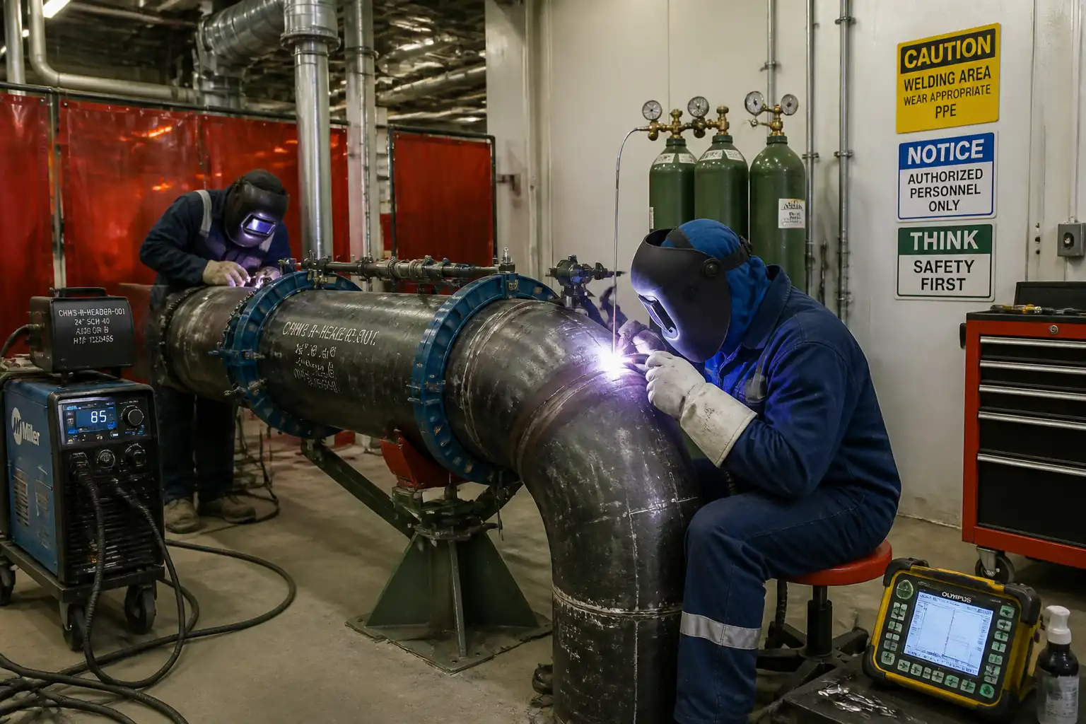
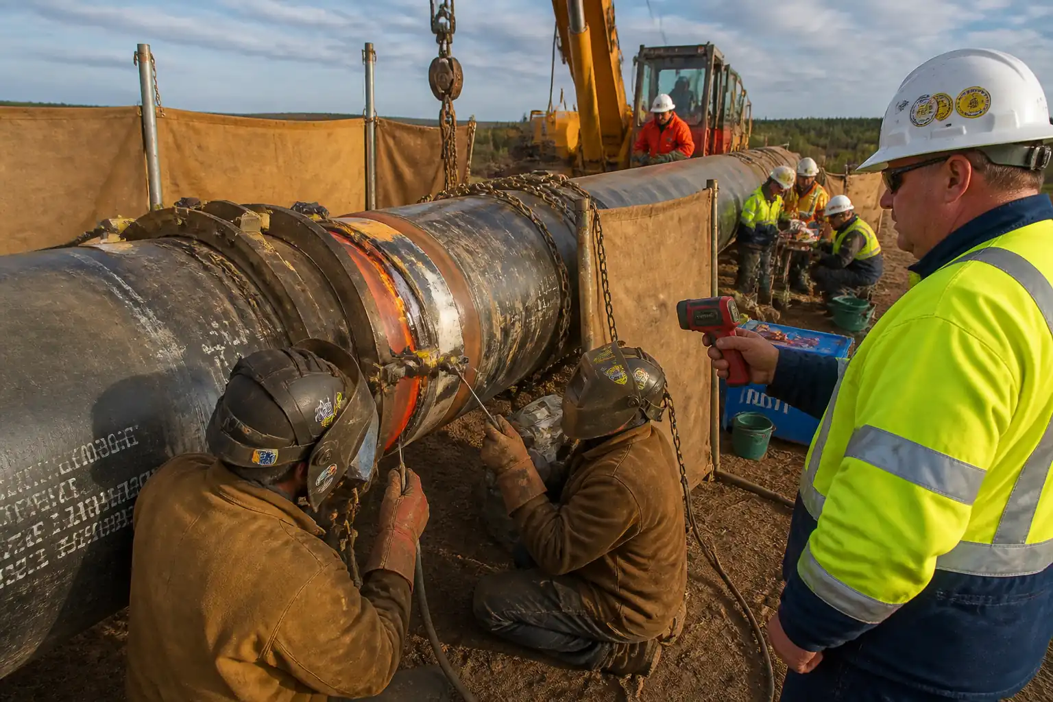
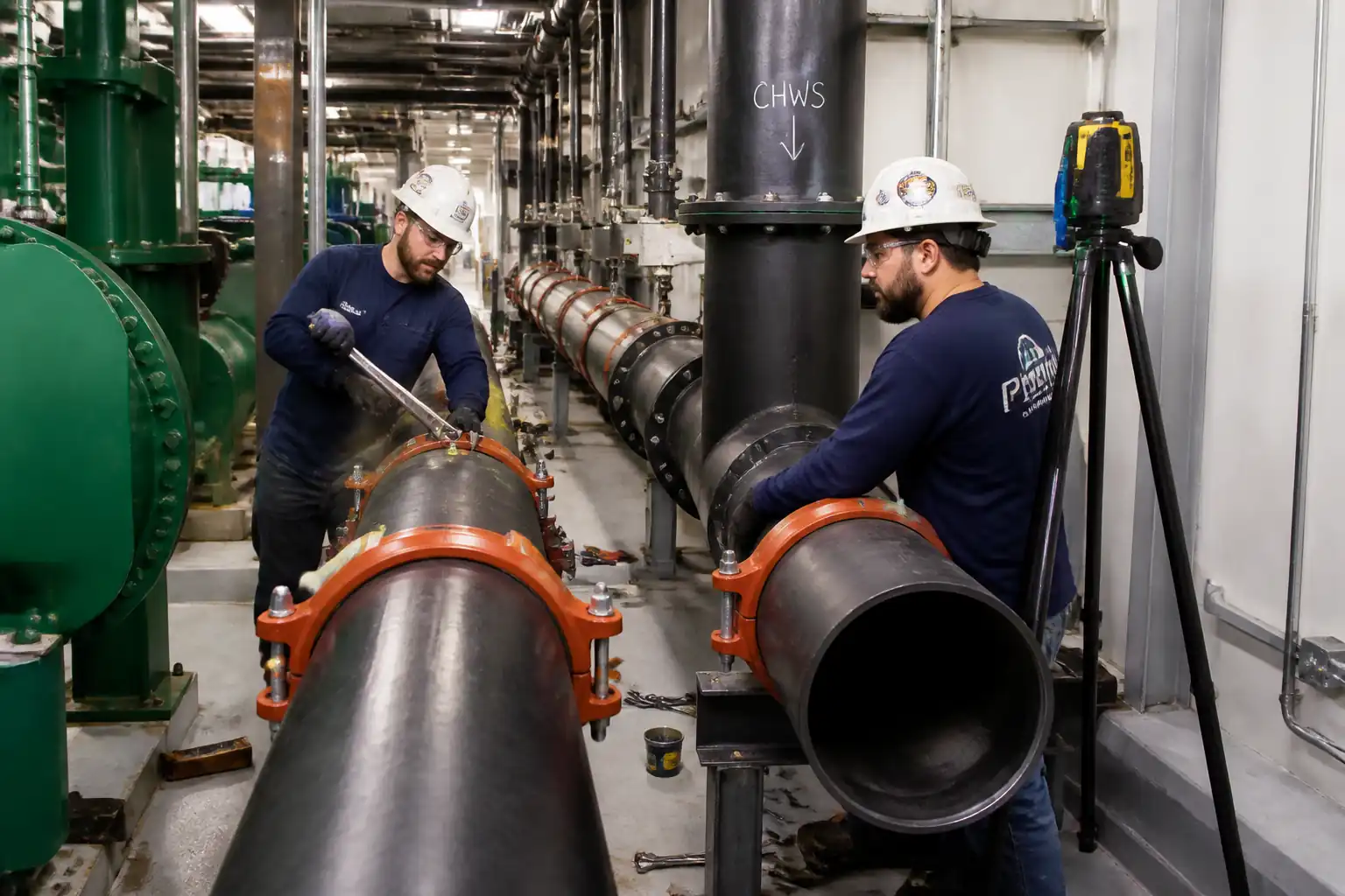
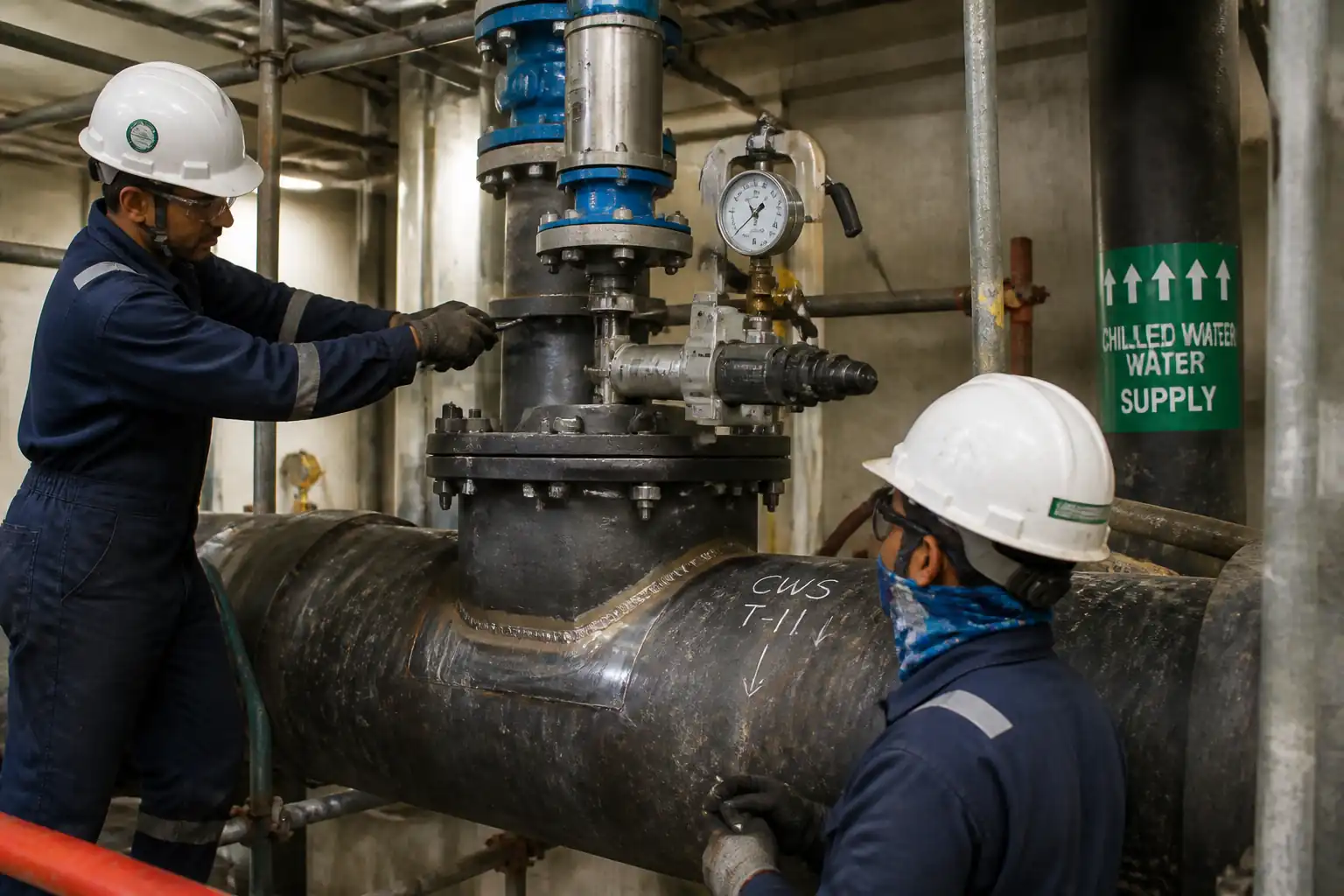
This method statement defines the engineering, fabrication, installation, hot tapping, and commissioning procedures for creating new branch connections on live, pressurized chilled water (CHW) piping systems using hot tapping. It covers specialized split-tee/reinforcement saddle welding, non-destructive testing (NDT), installation of an isolation valve and tapping machine, coupon cutting under pressure, flange make-up, functional testing, and documentation.
Inclusions
- Engineering assessment and calculations for hot tap suitability and reinforcement.
- Fabrication of split-tee/saddle and branch spool.
- Welder/WPS qualification and control.
- Surface preparation, fit-up, preheat, welding, and NDT (VT, PT/MT, UT where applicable).
- Valve selection, pressure rating verification, and pre-installation testing.
- Tapping machine set-up, pressure equalization, coupon cutting, and retrieval.
- Post-tap leak verification, flange closure/branch tie-in, and flushing.
- HSE controls for live-pressurized work, hot works, lifting, and water/glycol containment.
- QA/QC, ITP, records, and handover.
Exclusions
- Permanent system isolation/shutdown (not applicable to hot tap).
- Major civil works or supports outside the immediate tap location [Verify per project scope].
- Chemical water treatment adjustments post-works [By Client/O&M].
Key Constraints
- Work performed on a live, pressurized CHW line at typical 4–12°C and 6–16 bar MOP [Verify per project specifications].
- Maximum hot tap branch size, location clearances, and remaining wall thickness as per engineering assessment and applicable codes.
References
| Document Type | Reference / Number | Revision | Notes |
|---|---|---|---|
| ASME B31.3 (or ASME B31.9 for Building Services Piping) – Process/Building Services Piping | Materials, fabrication, examination, testing; select the applicable code based on the facility classification [Verify per project]. | ||
| ASME PCC-2 – Repair of Pressure Equipment and Piping (Hot Tapping and On-Line Branch Connections) | Engineering and execution guidance for hot tapping and branch reinforcement. | ||
| API 2201 – Safe Hot Tapping Practices in the Petroleum and Petrochemical Industries | Safety and procedural guidance; adapt to CHW service [Verify applicability per project HSE plan]. | ||
| ASME Section IX – Welding Qualifications | WPS/PQR and welder qualification for pressure boundary welds. | ||
| ASME Section V – Nondestructive Examination | General NDE methods, procedures, and calibration blocks. | ||
| ISO 17635 / ISO 23278 / ISO 3452 / ISO 9712 | General rules for NDT of welds; MT/PT techniques and personnel qualification. | ||
| ASME B16.5 / B16.47 – Pipe Flanges and Flanged Fittings | Flange classes and dimensions for valve/adapter flanges. | ||
| ASME B16.34 – Valves, Flanged, Threaded, and Welding End | Valve design and pressure-temperature ratings. | ||
| API 598 – Valve Inspection and Testing | Hydrostatic and seat leakage tests for valves. | ||
| ASTM A53 / ASTM A106 – Carbon Steel Pipe; ASTM A234 WPB – Wrought Carbon Steel Fittings | Typical CHW materials; verify per project MTO. |
Responsibilities
| Role | Responsibility | Name / Party |
|---|---|---|
| Project Manager | Project Manager | Main Contractor |
| Construction Manager | Construction Manager | Main Contractor |
| Welding Engineer | Welding Engineer | Main Contractor |
| Supervisor | Hot Tapping Specialist Supervisor | Approved Specialist Subcontractor |
| QA/QC Engineer | QA/QC Engineer | Main Contractor |
| NDT Technician | NDT Level II/III Personnel | Approved NDT Agency |
| HSE Officer | HSE Officer | Main Contractor |
| Engineer | Client/Engineer Representative | Client/Engineer |
Resources
| Resource Type | Description | Quantity | Remarks |
|---|---|---|---|
| Manpower | 1 | ||
| Manpower | 2–4 [Verify] | Carbon steel SMAW/GTAW | |
| Manpower | 2 | From approved specialist | |
| Manpower | 2 | Certified | |
| Manpower | 2 | IPAF or equivalent | |
| Manpower | 1–2 |
Materials
| Material | Specification / Grade | Quantity | Remarks |
|---|---|---|---|
| Isolation Valve, Flanged | ASME B16.34; API 598 tested; Body ASTM A216 WCB or equivalent; Seat compatible with CHW/glycol | ASME B16.5 Class 150/300 as per design pressure [Verify] | |
| Split-Tee/Full Encirclement Saddle with Branch | ASTM A106 Gr B / ASTM A53 Gr B body; ASTM A234 WPB branch; design per ASME B31.3/PCC-2; with tell-tale/vent holes | Material compatible with run pipe | |
| Flange Adapter/Hot Tap Machine Adapter | ASME B16.5; RF; material to match tee/valve | Class matched to valve/flange | |
| Gaskets | ASME B16.20 Spiral Wound or PTFE sheet [Verify]; potable-water-safe if applicable | Graphite/PTFE per service and temperature | |
| Bolting | ASTM A193 B7 studs / A194 2H nuts or per project | Lubricated with suitable anti-seize | |
| Welding Consumables | SMAW E7018 (low hydrogen) / GTAW ER70S-6 with appropriate flux/shielding | Per qualified WPS | |
| Pipe Insulation and Cladding | To match existing CHW system; vapor barrier; closed-cell insulation | For reinstatement after works |
Equipment
| Equipment | Capacity / Type | Quantity | Inspection Required |
|---|---|---|---|
| Hot Tapping Machine (e.g., TDW, Enerpac, or equivalent) | Sized to branch; pressure rating ≥ system MOP + margin | 1 | Calibration certificate |
| Isolation Valve (Gate/Plug/Ball, full-bore) | ASME Class per design; fire-safe not required for CHW | 1 | API 598 cert |
| Temperature Sticks/Infrared Thermometer | 0–300°C | 2 | Calibration |
| Ultrasonic Thickness Gauge (UTM) | 1–50 mm | 1 | Calibration |
| NDT Kits (PT/MT), UT if applicable | As per ISO/ASME | 1 set | Procedure + NDT personnel certs |
| Calibrated Torque Wrenches | Up to 500 N·m or as required | 2 | Calibration |
| MEWP/Scaffold and Rigging Gear | SWL tagged | As required | LOLER/Thorough exam [Verify per local regs] |
Prerequisites
- Approved method statement, risk assessment/JSA, and Permit-to-Work including Hot Work Permit [Verify per project HSE plan and local regulations].
- Engineering package: tie-in location drawings, isometrics, stress and support check, hot tap size (d), run pipe size (D), branch reinforcement calculations (per ASME B31.3/PCC-2), and minimum remaining wall thickness (t_rem) assessment using UTM corrosion survey.
- Confirmation of service conditions: fluid (water/glycol %), MOP, normal/maximum temperature, flow direction and velocity, chemistry/biocide data.
- Verification of hot tap feasibility: typical limits d/D ≤ 0.5–0.6; minimum spacing from existing welds ≥ 1.0 × run pipe diameter or ≥ 300 mm, whichever greater; avoid elbows/nozzles by ≥ 3 × branch diameter [Verify per project and PCC-2].
- Fabrication drawings and WPS/PQR approved; welders certified to ASME IX for positions applicable (e.g., 2F/3F/4F for saddles, 5G/6G if applicable).
- Valve and adapter flange class match; valve API 598 certificates; hydrostatic/seat test records.
- Calibration certificates for gauges, torque wrenches, UTM, thermometers, tapping machine indicators.
- Access platforms/MEWP erected and inspected; lifting plan; exclusion zones marked.
- Insulation removal plan and moisture control for CHW lines to prevent condensation during welding (temporary vapor barriers, localized heating wraps as needed).
- Spill response and containment plan for potential CHW/glycol release; drain/collection connections available; environmental approvals in place.
- Pre-job briefing and toolbox talk with all crew; emergency plan including rapid valve closure and containment.
- Client/Engineer notified and hold/witness points scheduled.
Method Sequence
| Step | Activity | Description | Responsibility | Inspection / Hold Point |
|---|---|---|---|---|
| 1 | Site verification and marking | Confirm exact tap location on run pipe; verify clearances, supports, and no nearby defects; mark centerlines and orientation of branch. | Construction Manager / Hot Tapping Supervisor | VT of pipe OD; UTM sampling grid set-out |
| 2 | Surface preparation & insulation removal | Remove insulation/cladding over adequate area; dry surface; remove coatings to bright metal over weld footprint + 50 mm. | Site Crew / Insulation Subcontractor | VT of prepared surface |
| 3 | UT thickness mapping | Conduct 100% UTM over footprint + 150 mm; map minimum wall thickness and corrosion patterns. | NDT Technician | Owner/Engineer witness (W) |
| 4 | Split-tee/saddle fit-up | Align split-tee halves; ensure snug fit with max root gap ≤ 3 mm; install temporary clamps; verify branch orientation and level. | Welding Team / Supervisor | Fit-up inspection (H) |
| 5 | Preheat and welding (split-tee to run pipe) | Preheat CS to 75–120°C [Verify per WPS]. SMAW E7018 low-H electrode; balanced sequence to limit distortion; interpass ≤ 250°C. Maintain continuous vent/tell-tale opening. | Certified Welder / Welding Engineer | WPS adherence check; temperature monitoring |
| 6 | Weld NDT (attachment welds) | After cooling, perform VT 100% then PT or MT 100% of saddle/tee welds. UT/PAUT for full-penetration butt seams of the tee if applicable. | NDT Technician Level II | Engineer witness (W) |
| 7 | Tell-tale/annulus leak test | Apply low-pressure air 1.0–1.5 bar through tell-tale; soap-solution check around weld perimeter. | QA/QC Engineer / NDT Technician | Hold point (H) |
| 8 | Seal tell-tale and coat | Weld close the vent/tell-tale as specified; PT on seal weld; apply primer/temporary coating to bare steel. | Welder / QA/QC | VT/PT |
| 9 | Valve and adapter flange installation | Mount adapter flange to split-tee; install gasket and isolation valve; align bolt holes; torque per pattern in 3–4 passes. | Hot Tapping Supervisor / Rigger | Bolt torque check |
| 10 | Pressure equalization and pre-tap checks | Connect pressure gauge; verify zero leaks; open valve slightly to equalize pressure within tapping machine housing once mounted. | Hot Tapping Technician | Functional check |
| 11 | Mount tapping machine and set cutter | Attach machine to valve flange; verify travel length > wall + tee thickness; set pilot drill and hole saw to required branch ID. | Hot Tapping Technician | Setup verification |
| 12 | Hot tap cutting (live) | Fully open valve; advance pilot and cutter at controlled feed and rpm; use only potable-water-safe lubricant if required [Verify]. Monitor pressure/temp. | Hot Tapping Technician | Engineer witness (W) |
| 13 | Retract cutter and close valve | Retract tool beyond valve seat; close isolation valve fully; verify tight shut-off. | Hot Tapping Technician | VT; pressure check |
| 14 | Remove machine and install blind/branch piping | De-mount tapping machine; install blind flange or connect branch spool; torque bolts to spec; align piping supports. | Construction Crew | Bolt torque check; alignment |
| 15 | Branch pressure test (off-line prior or on-branch as applicable) | Hydrotest the branch/valve assembly off-line before installation where feasible; otherwise, pneumatic/soap test flanged joints post-tap. | QA/QC Engineer | Hold point (H) |
| 16 | Flushing and swarf removal | Crack open valve slightly into controlled hose/tank to discharge swarf until clear; sample for particulates. | Hot Tapping Technician / O&M | Visual |
| 17 | Coating and insulation reinstatement | Apply corrosion protection coating; reinstall insulation and vapor barrier; seal penetrations. | Insulation Subcontractor | VT |
| 18 | Handover and documentation | Compile and submit as-builts, NDT, test certs, torque logs, calibration, coupon custody, and ITP closeout. | QA/QC Engineer | Final walkdown (W) |
Health, Safety, and Environment (HSE) – Safety Controls
Key Hazards and Controls
- Hazard: Release of pressurized CHW (water/glycol)
- Consequence: Rapid flooding, slip hazards, equipment damage, hypothermia.
- Engineering/Procedural Control: Validate valve rating and integrity; pre-job verification of pressure/temperature; emergency shut plan; secondary containment and drain paths prepared; limit personnel in exclusion zone; pressure gauges installed before cutting.
- Required PPE: Waterproof gloves, chemical-resistant gloves if glycol present, face shield + safety glasses, waterproof boots, arc-rated FR long sleeves for hot work, thermal layer as needed.
- Collective Measure: Barricades and drainage trays; spill berms; dedicated suction pump on standby.
-
Inspection/Permit/Supervision: Hot Work Permit; live system work authorization; HSE Officer present; pre-tap checklist signed by Supervisor and Engineer.
-
Hazard: Welding on live, fluid-filled pipe (heat sink effect)
- Consequence: Cold cracking, lack of fusion, structural failure of saddle.
- Engineering/Procedural Control: Low-hydrogen process; controlled preheat 75–120°C and interpass ≤ 250°C; maintain dry electrodes; monitor temps; use qualified WPS/PQR.
- Required PPE: Welding hood, leather gauntlets, FR clothing, hearing protection.
- Collective Measure: Fire watch with extinguishers; removal of combustibles within 10 m; welding screens.
-
Inspection/Permit/Supervision: WPS verification; welding parameter logs; NDT hold point.
-
Hazard: Tapping machine or valve failure under pressure
- Consequence: Jetting release, impact injuries.
- Engineering/Procedural Control: Use OEM-certified machine rated above system MOP; function test; ensure coupon retention device; double-check flange torque and gasket selection.
- Required PPE: Face shield, gloves, hard hat, safety glasses.
- Collective Measure: Exclusion zone during cutting; remote position of non-essential staff.
-
Inspection/Permit/Supervision: OEM maintenance record; pre-use inspection; Engineer witness.
-
Hazard: Working at height on pipe racks/plant rooms
- Consequence: Falls from height.
- Engineering/Procedural Control: Certified scaffold or MEWP; harness with lanyard; edge protection; tools tethered.
- Required PPE: Full body harness, lanyard, hard hat with chin strap, non-slip footwear.
- Collective Measure: Scafftag/MEWP daily checks; exclusion below; toe boards.
-
Inspection/Permit/Supervision: Working at Height Permit; competent supervisor.
-
Hazard: Lifting and positioning heavy valves/machines
- Consequence: Crush injuries, dropped objects.
- Engineering/Procedural Control: Lift plan; rated slings/shackles; tag lines; no standing under load.
- Required PPE: Hard hat, gloves, steel-toe boots.
- Collective Measure: Designated lifting zone; banksman control.
-
Inspection/Permit/Supervision: LOLER/Thorough Examination certificates; pre-lift briefing.
-
Hazard: Electrical hazards from powered equipment
- Consequence: Shock, fire.
- Engineering/Procedural Control: Use 110V center-tapped or suitable RCD; inspect cables; dry working area.
- Required PPE: Dielectric gloves where needed, dry gloves, eye protection.
- Collective Measure: RCD testing; cable management.
-
Inspection/Permit/Supervision: Portable appliance testing; permit.
-
Hazard: Noise and vibration during drilling
- Consequence: Hearing damage, hand-arm vibration.
- Engineering/Procedural Control: Limit exposure time; maintain equipment; use anti-vibration gloves.
- Required PPE: Hearing protection, gloves.
- Collective Measure: Noise signage; rotation of operators.
-
Inspection/Permit/Supervision: Noise assessment [Verify per local regs].
-
Hazard: Chemical exposure (glycol/biocides)
- Consequence: Skin/eye irritation, environmental harm.
- Engineering/Procedural Control: SDS review; sealed drainage; avoid aerosolization.
- Required PPE: Chemical-resistant gloves, goggles/face shield.
- Collective Measure: Spill kits; containment tanks.
-
Inspection/Permit/Supervision: COSHH/chemical permit [Verify per project HSE plan].
-
Hazard: Legionella/aerosolization (stagnant CHW)
- Consequence: Respiratory illness.
- Engineering/Procedural Control: Minimize spray; use hoses to closed containers; avoid atomizing leaks; coordinate with water treatment vendor.
- Required PPE: Respiratory protection if risk identified.
- Collective Measure: Ventilation; isolation of area.
- Inspection/Permit/Supervision: Hygiene assessment [Verify per project HSE plan and local regulations].
Environmental Controls
- CHW/Glycol Containment: Provide drip trays, inflatable pipe seals, and sump pumps. Collect any discharge into IBC tanks. Glycol-bearing water is hazardous to aquatic life; do not discharge to storm drains [Verify per local regulations].
- Spill Response: Spill kits (absorbent pads, booms) at point of work; trained responders assigned; immediate reporting and isolation.
- Waste Management: Segregate metal swarf/coupon for recycling; dispose of used consumables and PT/MT chemicals as per SDS and project waste plan.
- Noise Management: Restrict drilling to permitted hours; use acoustic screens where required.
- Air Quality: Use low-VOC cleaners; avoid aerosolizing CHW; control fumes during welding with local extraction where practicable.
- Energy/Water: Minimize flushing volume; recirculate through filter bag if approved.
- Documentation: Environmental checklist pre/post works; record volumes of any collected CHW/glycol and disposal manifests.
QA/QC
Quality Objectives
- Execute structurally sound, code-compliant hot tap with zero leakage and full documentation.
Controls and Tests
- Design Calculations: Verify d/D ratio, reinforcement area, allowable membrane stress, and t_rem ≥ required thickness including corrosion allowance.
- Materials Traceability: Heat numbers and MTCs for split-tee, branch, flanges, and bolts.
- Welding Quality: WPS/PQR approved; low-hydrogen control; electrode ovens (≥120°C) and quivers; interpass monitoring; weld maps.
- NDT: 100% VT + PT/MT of attachment welds; UT/PAUT of butt seams where applicable; tell-tale pneumatic leak test; records signed by Level II/III.
- Valve Testing: API 598 certificates and off-line hydro/seat tests prior to install where feasible.
- Dimensional/Alignment: Branch axis tolerance ±1°; flange face parallelism ≤ 0.5°; bolt protrusion 1–3 threads; torque within manufacturer range.
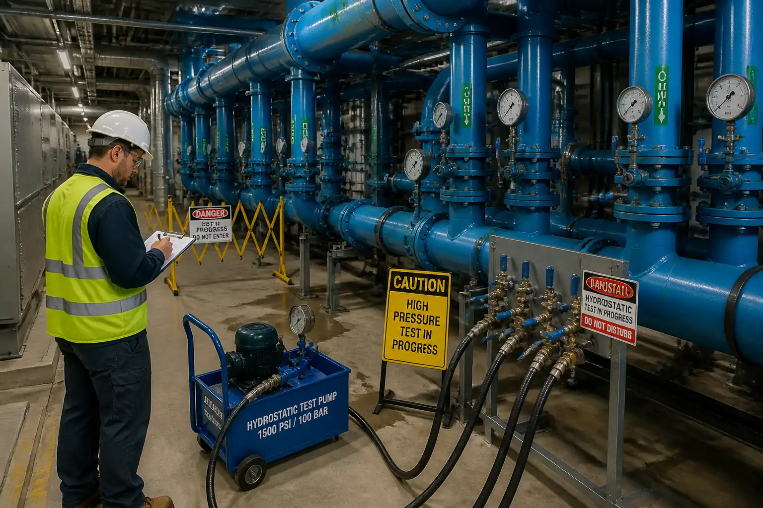
- Pressure/Leak Tests: Hydrostatic for branch at 1.5× design pressure [Verify]; soap test on flanged joints under line pressure; no visible leakage.
- Cleanliness/Flushing: Swarf cleared; two consecutive clean discharges confirmed.
- Documentation: ITP signed, NCR/CAR tracking, as-built redlines, coupon custody tag, calibration certs, final dossier.
Acceptance
- Conformance to ASME B31.3/B31.9 and ASME PCC-2; all ITP hold/witness points passed; zero leaks; Client/Engineer acceptance.
Attachments
- General arrangement and isometric drawings with hot tap location.
- Calculations: d/D ratio, reinforcement area, t_rem vs t_required, bolt torque values.
- Approved WPS/PQR and WPQ certificates.
- OEM data sheets: hot tapping machine, cutter, pilot drill, valve.
- ITP with signed checklists and hold/witness records.
- NDT procedures and reports (VT, PT/MT, UT where applicable).
- Hydrostatic/seat test certificates for valves/branch spool.
- Calibration certificates (torque, gauges, UTM, IR thermometer).
- Pre-job brief/TBT attendance sheet and permits (Hot Work, WAH, Electrical, Live System Authorization).
- Risk assessment/JSA.
- Environmental checklist and waste disposal manifests.
- As-built redlines and final handover dossier index.
This content is a read-only public reference. Download or customize to get an editable version.
ITP preview
The first inspection activities from the linked ITP for Method Statement for Hot Tapping Tie-In Connections on Live Pressurized Chilled Water (CHW) Piping:
| Activity | Inspection / Test | Acceptance Criteria | Responsibility | Record |
|---|---|---|---|---|
| Design and feasibility review | Check d/D, t_rem, reinforcement calcs per ASME B31.3/PCC-2 | Calculations approved; limits within code/company standards [Verify] | Welding Engineer / Client Rep (W) | Approved calc package |
| Material verification | Review MTCs/heat numbers for tee, branch, flanges, bolts | Materials match specifications/drawings | QA/QC Engineer | MTCs; material log |
| WPS/PQR and welder qualifications | Verify ASME IX qualifications | WPS/PQR approved; welders qualified for position/process | QA/QC Engineer | WPS/PQR; WPQ certs |
Showing 3 of 15 inspection activities. View full ITP →
Related Inspection and Test Plan
An Inspection and Test Plan (ITP) is available for Method Statement for Hot Tapping Tie-In Connections on Live Pressurized Chilled Water (CHW) Piping. The ITP defines the inspection activities, acceptance criteria, hold and witness points, responsible parties, and records required to verify the work described in this method statement.
View the Method Statement for Hot Tapping Tie-In Connections on Live Pressurized Chilled Water (CHW) Piping ITP →Frequently asked questions
Continue with related Quollnet resources connected to this method statement.