
Method Statement: Installation of Carbon Steel Chilled Water Piping with Grooved Mechanical Couplings – Method Statement
AI-assisted method statement with matching ITP, PDF download, and Excel export.
More than a static template
Unlike a downloadable Word or PDF template, this method statement is an AI-assisted editable starting point connected directly to a matching Inspection and Test Plan. Every section is structured, project-adaptable, and ready to export.
- AI-assisted drafting — Customize every section with AI for your specific project scope.
- Linked ITP — A matching inspection and test plan is generated alongside the method statement.
- Multiple export formats — Download as a formatted PDF or editable Excel spreadsheet.
- Editable starting point, not a final document — Review, verify, and adjust all content against your project requirements before use.
Static template vs. Quollnet workflow
| Feature | Static template | Quollnet |
|---|---|---|
| Project-specific content | Manual fill-in required | AI-assisted customization |
| Linked ITP | Separate document, no link | Matching ITP included |
| Export formats | Usually PDF only | PDF and Excel |
| Structured sections | Free-form layout | 13 standardized sections |
| Saved to your account | Local file only | Cloud-saved, reusable |
| Content accuracy | You verify everything | AI-assisted, you still verify |
| Cost | Often free but time-intensive | Free to customize and download |
What you can customize
When you save this method statement to your account, every section becomes editable. The following 13 sections are included:
- Scope — Defines the activity and its boundaries.
- References — Standards, specifications, and drawings.
- Responsibilities — Roles and accountabilities.
- Resources — Labour, plant, and equipment summary.
- Materials — Materials and compliance requirements.
- Equipment — Tools and equipment details.
- Prerequisites — Hold points and pre-conditions.
- Method sequence — Step-by-step construction sequence.
- Safety controls — HSE risk controls and PPE.
- Environmental controls — Environmental mitigation measures.
- QA/QC — Quality inspection and test requirements.
- ITP — Inspection and Test Plan table (has its own page).
- Attachments — Referenced drawings and documentation.
Why this method statement is used
This method statement is used to define and communicate the approved procedure for carrying out method statement: installation of carbon steel chilled water piping with grooved mechanical couplings on site. It ensures the work is planned in advance, the correct resources and controls are in place, and all personnel understand responsibilities, sequence, quality requirements, and safety controls before work begins. It aligns site execution with the documented scope and acceptance expectations.
Who uses this method statement
This method statement is used by contractors, site supervisors, project engineers, QA/QC engineers, HSE officers, consultants, and client representatives. It serves as a shared reference for planning, execution, supervision, inspection, and approval of the activity on site.
When it is prepared and submitted
The method statement is prepared before the work activity starts and submitted as part of the pre-construction documentation package for review and approval.
Who reviews or approves it
The method statement is usually submitted to the client representative, consultant, resident engineer, or project management consultant for review and approval before the work commences.
Important approval note
This method statement is an AI-assisted editable starting point, not a pre-approved document. Before use on any project, all content must be reviewed and approved by the relevant parties (superintendent, principal contractor, or client representative) in accordance with your contract and project quality plan.
For example: if your specification requires a departure from a referenced standard, that departure must be documented and approved separately — this method statement will not capture that automatically. Always verify against your applicable drawings, specifications, and regulatory requirements.
Method statement content
Scope
Overview
This method statement covers the end-to-end installation of carbon steel chilled water (CHW) supply and return piping systems using roll-grooved pipe ends and grooved mechanical couplings and fittings. It includes material receipt, pipe cutting and roll grooving, groove dimension measurement, gasket selection and lubrication, coupling assembly and bolt torquing, alignment and support installation, support spacing control, system flushing and pressure testing, punch-list rectification, and documentation.
Included Systems/Activities
- Carbon steel CHW mains, branches, and risers above ground within plant rooms, risers, and service corridors.
- Roll grooving of pipe ends, dimensional verification, and QA/QC records.
- Installation of grooved couplings, fittings, valves, and accessories (strainers, air vents, drains) with compatible grooved ends/adapters.
- Hanger and support installation, alignment, and spacing verification.
- Hydrostatic pressure testing and system flushing/cleaning.
Exclusions
- Thermal insulation and vapor barriers (by separate method).
- Chemical dosing/passivation beyond flushing unless specified.
- Underground piping and welding.
Key Objectives
- Achieve leak-free, properly aligned CHW piping with verified groove geometry and coupling assembly per manufacturer data and applicable standards.
- Maintain support spacing and alignment tolerances to prevent undue load on equipment nozzles and accommodate thermal movement.
- Complete QA/QC and ITP with traceable records.
References
| Document Type | Reference / Number | Revision | Notes |
|---|---|---|---|
| ASME B31.9: Building Services Piping [Verify applicability] | Design, fabrication, examination, testing requirements for building piping. | ||
| AWWA C606: Grooved and Shouldered Joints [Verify applicability] | Dimensional requirements for grooves and coupling engagement. | ||
| MSS SP-58, SP-69, SP-89: Pipe Hangers and Supports | Selection, installation, and maintenance of supports. | ||
| ASTM A53/A106 (Carbon Steel Pipe) [Verify grade/schedule] | Material requirements and markings for CS pipe. | ||
| ASTM A536 (Ductile Iron) for grooved fittings [Verify] | Material for grooved fittings and couplings housings. | ||
| ISO 1461 (Galvanizing) / ISO 12944 (Coatings) [As applicable] | For hot-dip galvanized supports or painted/epoxy-coated pipe. | ||
| Manufacturer’s Installation Instructions (e.g., Victaulic, GRINNELL) | Groove dimensions, gasket type, bolt torque, angular deflection, and end gap limits. | ||
| ASHRAE Guidelines for Hydronic Systems [Verify] | Flushing velocities, cleaning, and commissioning good practice. |
Responsibilities
| Role | Responsibility | Name / Party |
|---|---|---|
| Project Manager | Project Manager | Contractor |
| Construction Manager | Construction/Mechanical Manager | Contractor |
| QA/QC Engineer | QA/QC Engineer | Contractor |
| Site Engineer | Site Engineer / Supervisor | Contractor |
| HSE Officer | HSE Officer | Contractor |
| Consultant | Client/Consultant Representative | Consultant |
Resources
| Resource Type | Description | Quantity | Remarks |
|---|---|---|---|
| Supervision | 1 per crew | ||
| Skilled Labor | 1 | Certified by manufacturer/trained [Verify] | |
| Skilled Labor | 2–4 | ||
| Skilled Labor | 1–2 | Certified [Verify] | |
| QA/QC | 1 | ||
| HSE | 1 (shared) |
Materials
| Material | Specification / Grade | Quantity | Remarks |
|---|---|---|---|
| Carbon Steel Pipe | ASTM A53 Gr B or ASTM A106 Gr B; Schedule per design [Verify] | ||
| Grooved Mechanical Couplings and Fittings | Conforming to AWWA C606 and manufacturer data (e.g., Victaulic/GRINNELL) | ||
| Gaskets (EPDM) | Manufacturer’s recommended grade for CHW; hydrocarbon-free | ||
| Gasket Lubricant | Manufacturer-approved, silicone- or glycol-based, compatible with EPDM | ||
| Bolts, Nuts, Washers | Per coupling manufacturer; property class per data sheet | ||
| Pipe Hangers and Supports | MSS SP-58/69/89; hot-dip galvanized per ISO 1461 or epoxy coated [Verify] |
Equipment
| Equipment | Capacity / Type | Quantity | Inspection Required |
|---|---|---|---|
| Power Roll Grooving Machine | e.g., 2"–24" (DN50–DN600) [Verify] | Pre-use inspection; guards in place | |
| Band Saw / Pipe Cutter | To suit pipe OD range | PAT and guard checks | |
| Calipers & Groove Gauges | 0–300 mm calipers; dedicated groove gauge set | Calibration certificate valid [≤6 months] | |
| Torque Wrench | 40–400 N·m or as required | Calibration certificate valid [≤6 months] | |
| Handling & Access Equipment | WLL per lift plan; scaffolds per design | Lifting gear certificates; scaffold tags green |
Prerequisites
- Approved shop drawings, coordinated BIM/spool drawings, and latest IFC revisions available at workface.
- Approved material submittals for pipe, couplings/fittings, gaskets, lubricant, and supports.
- Manufacturer installation instructions and torque/groove dimension tables at workface.
- ITP and inspection forms approved by Client/Consultant.
- Calibrated instruments: torque wrenches and measuring tools (certificates ≤ 6 months old or per project).
- Work permits: Hot Work (if applicable), Working at Height, Lifting Plan/Permit to Lift, and area access permits. [Verify per project HSE plan and local regulations]
- Verified utilities and clash-free route; clearances and sleeves/openings installed and accepted.
- Scaffolding/MEWP inspected and tagged; exclusion zones established for overhead work.
- Materials inspected upon receipt (MIR approved) with heat numbers and traceability maintained.
- Crew trained and briefed via task-specific JSA/toolbox talk; machine operators competent/certified.
- Flushing and pressure testing plan prepared, including temporary flushing connections, drain points, gauges, and calibrated test pump.
Method Sequence
| Step | Activity | Description | Responsibility | Inspection / Hold Point |
|---|---|---|---|---|
| 1 | Work area setup and verification | Barricade work area; verify drawings/route, elevations, expansion provisions, and equipment nozzle orientations. Confirm supports locations marked on structure with anchors compatible to base material. | Site Engineer / Supervisor | Pre-start check |
| 2 | Material receipt and inspection | Check pipe/fittings/couplings for correct size/schedule/ratings, coating condition, straightness; verify gaskets type (EPDM for CHW) and compatibility with lubricant. Reject damaged/out-of-round items. | QC Inspector | Visual and dimensional |
| 3 | Pipe cutting and end preparation | Measure and mark cut length; cold cut using band saw/pipe cutter. Deburr ID/OD; ensure square cut. Clean ends free of scale/oil. Do not flame-cut grooved ends. | Pipe Fitter | In-process check |
| 4 | Roll grooving setup and trial | Set grooving machine with correct roll set per pipe diameter/schedule. Perform trial groove on sacrificial piece and adjust feed to achieve target dimensions per manufacturer/AWWA C606. | Grooving Operator | Witness point |
| 5 | Production roll grooving | Groove pipe ends smoothly with continuous feed. Avoid over-grooving. Clean groove area after forming. Protect machined ends. | Grooving Operator | Process monitoring |
| 6 | Groove measurement and acceptance | Measure each grooved end using groove gauge/calipers: Groove OD (A), Groove width (B), Groove depth (C), Distance from pipe end (D), and flare. Check out-of-roundness. | QC Inspector | Hold point |
| 7 | Pre-assembly alignment and support preparation | Install temporary pipe stands/rollers. Verify anchor/guide locations and install fixed points as per drawings. Provide guides near equipment to control load and expansion movement. | Site Engineer | Check layout |
| 8 | Gasket inspection and lubrication | Inspect gasket for damage; confirm grade (EPDM) and size. Apply thin, even film of approved lubricant to gasket exterior and sealing lips. Do not use petroleum products. | Pipe Fitter | Visual |
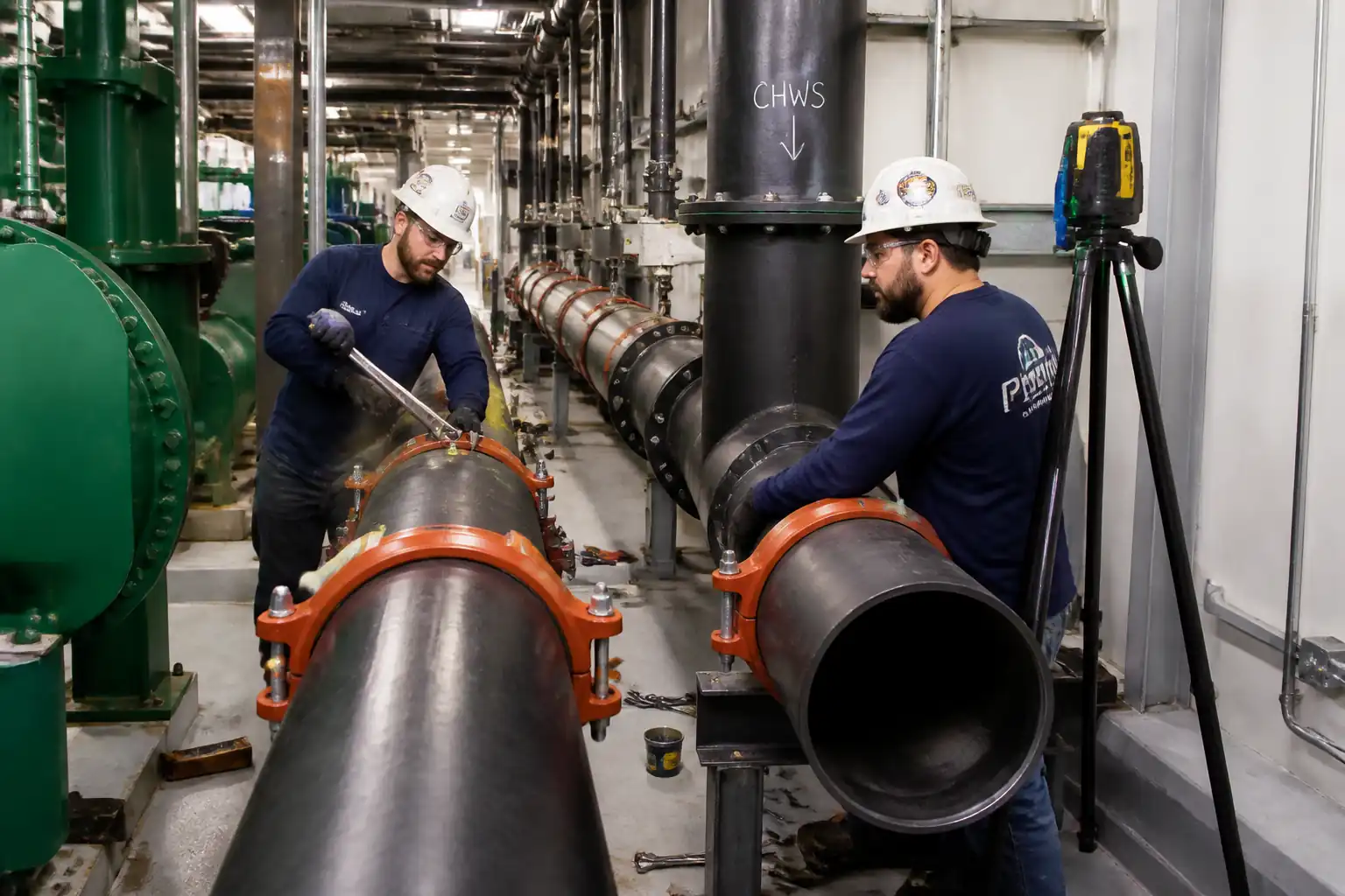
| 9 | Coupling assembly | Place gasket on first pipe end with gasket centerline over groove; bring pipe ends together and center gasket over joint. Fit housings ensuring keys fully engage grooves. Insert bolts/nuts and hand tighten. | Pipe Fitter | In-process check |
| 10 | Bolt torquing | Tighten nuts alternately and evenly in cross-pattern using calibrated torque wrench to manufacturer torque. Confirm metal-to-metal housing contact where specified and torque-mark bolt heads/nuts. | Pipe Fitter / QC | Witness point |
| 11 | Alignment and support spacing control | Use laser/stringline to verify alignment. Adjust hangers/rollers to remove stress. Confirm support spacing against schedule and install sway bracing where required. Ensure no load on equipment nozzles; use temporary jigs if needed. | Site Engineer / QC | Inspection point |
| 12 | Valve and accessory installation | Install grooved valves, strainers, drains, and air vents with correct orientation and support independently to avoid loading the piping/couplings. | Pipe Fitter | Visual |
| 13 | Flushing/cleaning | Install temporary spool/hoses; flush with clean water at velocity ≥ 1.5 m/s (typ.) until discharge runs clear; strain debris. Record duration, flow, and clarity. | Site Engineer | Witness point |
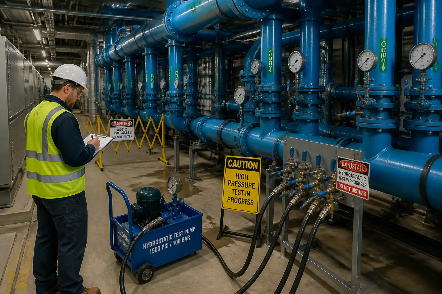
| 14 | Hydrostatic pressure test | Isolate and fill line slowly; vent high points; pressurize using calibrated pump to test pressure (typically 1.5 × design or per spec). Stabilize, then hold for specified duration (e.g., 2 hours). Monitor for leaks/pressure drop. | QC Engineer | Hold point |
| 15 | Draining, drying, reinstatement | Release pressure; drain to approved point; remove temporary flushing assemblies; reinstall strainers baskets; dry as required to prevent corrosion; reinstate valves to normal positions; install identification tags. | Site Engineer | Visual |
| 16 | Punch-list closeout and documentation | Rectify snags; submit as-built redlines, test/flushing records, torque logs, groove check sheets, MIR/IR approvals, and O&M manuals. | Project Manager / QA/QC | Final inspection |
Health, Safety, and Environment (HSE) - Safety Controls
Task-specific hazards and controls
- Hazard: Roll grooving machine pinch points and rotating parts
- Likely consequence: Crush/amputation injuries, entanglement
- Engineering/procedural control: Machine guards in place; foot-pedal deadman; set-up on level surface; use push sticks and clamps; no loose clothing; lock-out/tag-out during roll change/maintenance
- Required PPE: Cut-resistant gloves (when handling), safety glasses with side shields, long sleeves, safety boots
- Collective measure: Physical barrier around machine and exclusion zone; signage
-
Inspection/permit/supervision: Pre-use inspection checklist; competent operator only; supervisor sign-off
-
Hazard: Pipe handling and lifting (spools, long lengths)
- Likely consequence: Struck-by, crush injuries, dropped loads
- Engineering/procedural control: Use taglines; rated slings/shackles with valid certificates; balanced lift points; follow lift plan and banksman signals; do not stand under suspended loads
- Required PPE: Helmet with chin strap, gloves, safety boots
- Collective measure: Exclusion zone and barricades during lifts
-
Inspection/permit/supervision: Permit to Lift; lifting gear inspection tags; banksman present
-
Hazard: Working at height on pipe racks/ceilings
- Likely consequence: Falls from height
- Engineering/procedural control: Certified scaffold/MEWP with guardrails; 100% tie-off for open edges; use approved anchor points; tools tethered
- Required PPE: Full-body harness with double lanyard, helmet with chin strap
- Collective measure: Edge protection, toe boards, platform inspection tags
-
Inspection/permit/supervision: Work at Height permit; daily scaffold/MEWP inspection; supervisor oversight
-
Hazard: Cutting and deburring operations
- Likely consequence: Lacerations, eye injury, sparks (if hot work)
- Engineering/procedural control: Prefer cold cutting; if hot work, fire blankets and spark containment; maintain housekeeping; use correct blades/cutters
- Required PPE: Safety glasses/face shield, gloves
- Collective measure: Fire extinguisher nearby; remove combustibles
-
Inspection/permit/supervision: Hot Work Permit if applicable; fire watch during/30 min after work [Verify per project HSE plan and local regulations]
-
Hazard: Bolt torquing and pressurized systems during testing
- Likely consequence: Snap-back, sudden release of stored energy, leaks causing slips
- Engineering/procedural control: Use calibrated torque wrenches; pressurize gradually; stand clear of potential failure plane; verify all couplings fully engaged before testing
- Required PPE: Eye protection, gloves
- Collective measure: Test area barricaded with pressure warning signs
-
Inspection/permit/supervision: Test procedure approval; calibrated gauges/pump; supervisor and QC present
-
Hazard: Noise and vibration from machinery
- Likely consequence: Hearing loss
- Engineering/procedural control: Maintain equipment; limit exposure time; schedule noisy tasks
- Required PPE: Hearing protection (ear defenders/plugs)
- Collective measure: Noise barriers if practicable
-
Inspection/permit/supervision: Noise monitoring as required
-
Hazard: Chemical exposure to gasket lubricant/cleaners
- Likely consequence: Dermatitis, eye irritation
- Engineering/procedural control: Use manufacturer-approved products; avoid skin contact; provide SDS and training; use dispensers to avoid spills
- Required PPE: Nitrile gloves, goggles
- Collective measure: Spill kits available; ventilation in plant rooms
-
Inspection/permit/supervision: SDS on site; COSHH assessment [Verify]
-
Hazard: Manual handling and awkward postures
- Likely consequence: Strains and sprains
- Engineering/procedural control: Use pipe rollers, stands, and team lifts; apply ergonomic techniques; rotate tasks
- Required PPE: Gloves, supportive footwear
- Collective measure: Use of mechanical aids prioritized
-
Inspection/permit/supervision: Manual handling training verified
-
Hazard: Interaction with other trades
- Likely consequence: Collisions, dropped objects
- Engineering/procedural control: Coordination meetings and SIMOPS plan; staggered workfronts; overhead protection (debris nets)
- Required PPE: Standard site PPE
- Collective measure: Workface coordination board
- Inspection/permit/supervision: Daily coordination and permit review
[All controls to be verified per project HSE plan and local regulations.]
Environmental Controls
- Flushing water management
- Risk: High-volume discharge with silt/particles and chlorine if potable water used
- Control: Route to approved drain via sediment bag/filter; dechlorinate if required; meter/record volume; obtain discharge permit; prevent erosion with energy-dissipation mats
-
Inspection/permit: Discharge permit, periodic turbidity checks
-
Chemical/lubricant management
- Risk: Lubricant spills contaminating floors/drains
- Control: Use squeeze bottles; trays/absorbent pads under assembly areas; immediate spill cleanup; store chemicals in bunded area; dispose per SDS
-
Inspection/permit: Spill kit availability; SDS and COSHH assessment [Verify]
-
Waste management
- Risk: Scrap metal, used gaskets/packaging
- Control: Segregate scrap steel for recycling; dispose gaskets/packaging via approved contractor; keep records
-
Inspection/permit: Waste transfer notes
-
Noise and energy
- Risk: Nuisance to occupants/neighbors; high energy use
- Control: Schedule noisy tasks in permitted hours; maintain equipment; shut down idling machines
-
Inspection/permit: Noise monitoring as required by permit
-
Dust/particulates and metal swarf
- Risk: Indoor air quality degradation, slip hazards
- Control: Cold-cutting preferred; use swarf collection trays; routine housekeeping; wet-wipe if required
-
Inspection/permit: Housekeeping inspections
-
Coatings/paint touch-up (if applicable)
- Risk: VOC release; overspray
- Control: Low-VOC products; brush/roller application; local containment and ventilation; waste management per MSDS
- Inspection/permit: Paint store compliance; MSDS on site
Quality Assurance / Quality Control
General
- All works per ASME B31.9, AWWA C606, MSS SP-58/69/89, approved drawings, and manufacturer instructions.
- Instruments (torque wrenches, gauges) to have valid calibration certificates ≤ 6 months old or per project.
Inspection and Testing Frequencies
- Material receiving: 100% visual and documentation review (MIR).
- Roll grooving: Trial groove witnessed at start of each size/schedule change; first-off inspection then 1 in 10 ends minimum, plus any suspect ends.
- Groove geometry: 100% measurement for first 5 ends, then statistical sampling 1 in 10; revert to 100% if nonconformity found.
- Coupling installation: 100% visual; bolt torque verification 10% of joints per shift per size minimum; increase to 100% if nonconformities.
- Alignment/supports: 100% verification at each support/anchor/guide.
- Flushing: Witness; turbidity check as specified.
- Hydrotest: Hold point; 100% of system.
Acceptance Criteria (typical)
- Groove dimensions A/B/C/D within manufacturer/AWWA C606 tolerances. No cracks, tears, or excessive flare (≤ 1.5 mm typical) [Verify].
- Correct gasket type (EPDM) and lubricant compatibility; no petroleum-based products.
- Couplings: Housing keys fully engaged; even gasket compression; torque within manufacturer range; metal-to-metal contact where specified; torque-marking applied.
- Alignment: Deviation ≤ 3 mm per 3 m (typ.) and within design tolerances; angular deflection per coupling limits; no load on equipment nozzles; support spacing per approved schedule.
- Hydrotest: No visible leaks; pressure maintained for specified duration without unacceptable drop per ASME B31.9/project spec.
- Flushing: Clear discharge; turbidity ≤ 5 NTU or as project specifies; strainers cleaned.
Documentation
- MIR, calibration certificates, groove inspection sheets, torque logs, IR/ITR forms, flushing logs, pressure test certificates, as-built redlines, and NCR/CCF if applicable.
Nonconformance and Corrective Action
- Stop work on affected section; identify and quarantine nonconforming items; issue NCR; perform root-cause analysis; rework or replace; increase inspection frequency until process control re-established.
Attachments
- Manufacturer data sheets and installation manuals for couplings, gaskets, and lubricant (torque tables and groove dimension charts included)
- Approved shop drawings and coordinated spool drawings
- Hanger/support schedule and details (MSS SP-58/69 references)
- Calibration certificates for torque wrenches and measuring devices
- Lift plan and lifting gear certificates
- JSA/Method-specific risk assessment and permits (Hot Work, Work at Height, Permit to Lift)
- Flushing and pressure test procedures and permits to discharge
- Sample forms: MIR, IR/ITR, groove inspection sheet, torque log, alignment & support checklist, flushing log, pressure test certificate
This content is a read-only public reference. Download or customize to get an editable version.
ITP preview
The first inspection activities from the linked ITP for Method Statement: Installation of Carbon Steel Chilled Water Piping with Grooved Mechanical Couplings:
| Activity | Inspection / Test | Acceptance Criteria | Responsibility | Record |
|---|---|---|---|---|
| Material receiving (pipe, couplings, gaskets, supports) | Verify make/model/ratings; visual for damage/coating; review MTCs and approvals | Materials match approved submittals; markings traceable; no damage/out-of-roundness > 1% OD [Verify] | QC Inspector / Consultant (W) | MIR; Receiving inspection report; MTCs |
| Roll grooving setup trial | Check roll set selection; produce trial groove; measure A/B/C/D/flare | All dimensions within manufacturer/AWWA C606 tolerance; no cracks/tears; acceptable flare | QC Inspector / Consultant (W) | Groove setup sheet; IR |
| Production groove inspection | Sampling inspection of groove geometry; surface finish; out-of-roundness | Within tolerance; finish smooth; out-of-roundness ≤ 1% OD [Verify] | QC Inspector | Groove inspection sheets |
Showing 3 of 9 inspection activities. View full ITP →
Related Inspection and Test Plan
An Inspection and Test Plan (ITP) is available for Method Statement: Installation of Carbon Steel Chilled Water Piping with Grooved Mechanical Couplings. The ITP defines the inspection activities, acceptance criteria, hold and witness points, responsible parties, and records required to verify the work described in this method statement.
View the Method Statement: Installation of Carbon Steel Chilled Water Piping with Grooved Mechanical Couplings ITP →Frequently asked questions
Continue with related Quollnet resources connected to this method statement.