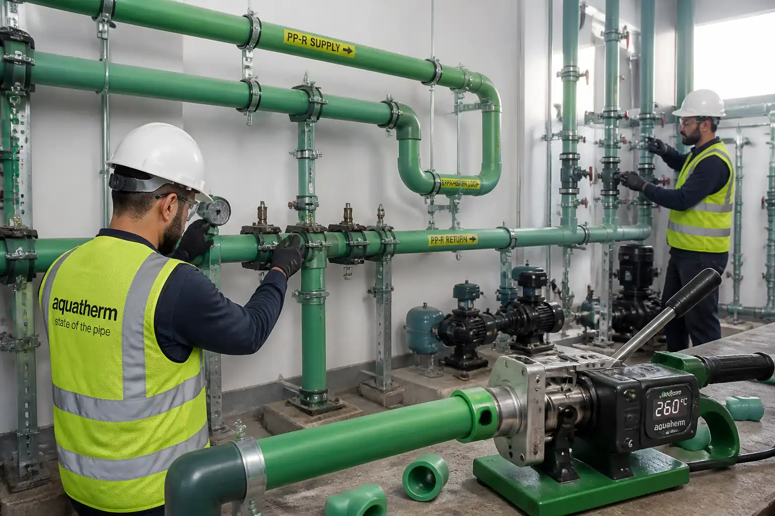

Method Statement: Installation of PP-R (Polypropylene Random Copolymer) Hot & Cold Water Supply Piping – Method Statement
AI-assisted method statement with matching ITP, PDF download, and Excel export.
More than a static template
Unlike a downloadable Word or PDF template, this method statement is an AI-assisted editable starting point connected directly to a matching Inspection and Test Plan. Every section is structured, project-adaptable, and ready to export.
- AI-assisted drafting — Customize every section with AI for your specific project scope.
- Linked ITP — A matching inspection and test plan is generated alongside the method statement.
- Multiple export formats — Download as a formatted PDF or editable Excel spreadsheet.
- Editable starting point, not a final document — Review, verify, and adjust all content against your project requirements before use.
Static template vs. Quollnet workflow
| Feature | Static template | Quollnet |
|---|---|---|
| Project-specific content | Manual fill-in required | AI-assisted customization |
| Linked ITP | Separate document, no link | Matching ITP included |
| Export formats | Usually PDF only | PDF and Excel |
| Structured sections | Free-form layout | 13 standardized sections |
| Saved to your account | Local file only | Cloud-saved, reusable |
| Content accuracy | You verify everything | AI-assisted, you still verify |
| Cost | Often free but time-intensive | Free to customize and download |
What you can customize
When you save this method statement to your account, every section becomes editable. The following 13 sections are included:
- Scope — Defines the activity and its boundaries.
- References — Standards, specifications, and drawings.
- Responsibilities — Roles and accountabilities.
- Resources — Labour, plant, and equipment summary.
- Materials — Materials and compliance requirements.
- Equipment — Tools and equipment details.
- Prerequisites — Hold points and pre-conditions.
- Method sequence — Step-by-step construction sequence.
- Safety controls — HSE risk controls and PPE.
- Environmental controls — Environmental mitigation measures.
- QA/QC — Quality inspection and test requirements.
- ITP — Inspection and Test Plan table (has its own page).
- Attachments — Referenced drawings and documentation.
Why this method statement is used
This method statement is used to define and communicate the approved procedure for carrying out method statement: installation of pp-r (polypropylene random copolymer) hot & cold water supply piping on site. It ensures the work is planned in advance, the correct resources and controls are in place, and all personnel understand responsibilities, sequence, quality requirements, and safety controls before work begins. It aligns site execution with the documented scope and acceptance expectations.
Who uses this method statement
This method statement is used by contractors, site supervisors, project engineers, QA/QC engineers, HSE officers, consultants, and client representatives. It serves as a shared reference for planning, execution, supervision, inspection, and approval of the activity on site.
When it is prepared and submitted
The method statement is prepared before the work activity starts and submitted as part of the pre-construction documentation package for review and approval.
Who reviews or approves it
The method statement is usually submitted to the client representative, consultant, resident engineer, or project management consultant for review and approval before the work commences.
Important approval note
This method statement is an AI-assisted editable starting point, not a pre-approved document. Before use on any project, all content must be reviewed and approved by the relevant parties (superintendent, principal contractor, or client representative) in accordance with your contract and project quality plan.
For example: if your specification requires a departure from a referenced standard, that departure must be documented and approved separately — this method statement will not capture that automatically. Always verify against your applicable drawings, specifications, and regulatory requirements.
Method statement content
Scope
Overview
This method statement covers the complete installation of PP‑R (Polypropylene Random Copolymer, Type 3) hot and cold potable water supply piping within buildings, including:
- Socket fusion welding using calibrated welding machines (heater plate temperature regulation and controlled heating/assembly/cooling times)
- Direct pipe alignment and jointing tolerances
- Thermal expansion calculation and fabrication of expansion loops/compensators, anchors and sliding supports
- Pipe support selection and spacing for pressure piping (hot and cold service)
- Pressure testing, flushing, and (where specified) disinfection
- Identification and handover records
System Boundaries
- From outlet of water meters/pump sets/riser take-offs to terminal service valves and equipment isolation points
- Includes transition fittings to metallic valves/manifolds and sleeves through walls/floors
- Excludes civil works, permanent insulation/firestopping unless noted by project scope
Constraints and Assumptions
- All dimensions, pressure ratings (PN/SDR), temperature classes, insulation requirements, and sterilization concentrations to be confirmed by project specifications [Verify per project specifications].
- Sequence coordinated with architectural finishes and MEP trades to avoid rework.
References
| Document Type | Reference / Number | Revision | Notes |
|---|---|---|---|
| Standard | EN ISO 15874 (all parts) | Defines materials, dimensions, fitness for purpose, and installation guidance. | |
| Standard | ISO 12162 | Material designation (e.g., PP-R Type 3) and pressure/temperature classes. | |
| Standard | BS EN 806-4 | Pressure test, flushing, and disinfection guidance for building water systems. | |
| Standard | AWWA C651 [Use only if specified] | Typically for mains; building systems normally follow EN 806-4 [Verify per project specifications]. | |
| Standard | ISO 14732 | PP‑R socket fusion operators to be trained/qualified per manufacturer; ISO 14732 as benchmark. | |
| Standard | ISO/IEC 17025 | Calibration certificates for gauges/thermometers from accredited labs. | |
| Standard | EN 12266-1/-2 | For brass/stainless transition fittings and valves integrated into PP‑R networks. |
Responsibilities
| Role | Responsibility | Name / Party |
|---|---|---|
| Project Manager | Project Manager | Contractor |
| MEP Engineer | MEP Engineer | Contractor |
| QA/QC Engineer | QA/QC Engineer | Contractor |
| Foreman | Plumbing Supervisor/Foreman | Contractor |
| Welder | Certified PP‑R Welder | Contractor |
| HSE Officer | HSE Officer | Contractor |
| Engineer | Resident Engineer / Client Rep | Engineer/Client |
Resources
| Resource Type | Description | Quantity | Remarks |
|---|---|---|---|
| Personnel | PM, MEP Engineer, QA/QC Engineer, HSE Officer | 4 | Full-time/part-time per project scale |
| Personnel | Foreman, Certified PP‑R Welders, Plumbers, Helpers | 1 Foreman + 2–6 Welders + 2–6 Plumbers + 2–6 Helpers [Verify] | Crew size per workfront |
| External | Calibration lab, water testing lab (microbiological/chemical) | As required | Labs accredited to ISO/IEC 17025 |
Materials
| Material | Specification / Grade | Quantity | Remarks |
|---|---|---|---|
| PP‑R straight lengths/coil | Green/natural/UV-stabilized as specified | As per BOQ | |
| PP‑R molded | Same PN/SDR as pipe | As per BOQ | |
| Brass/SS with PP‑R unions | Pressure class per design [Verify] | As per BOQ | |
| Steel components | Fire rating where required [Verify] | As per layout | |
| Metal/PVC sleeves; intumescent sealant | Compatible with PP‑R | As required | |
| Water; sodium hypochlorite | Chlorine 20–50 mg/L typical for building systems [Verify] | As required |
Equipment
| Equipment | Capacity / Type | Quantity | Inspection Required |
|---|---|---|---|
| Socket fusion welder | DN20–DN110 | 1 per welding team | Calibration/verification of temperature (IR thermometer) |
| Cutters/deburrers | Sets per crew | Tool condition check | |
| Clamps | As needed | Visual condition | |
| Measuring/QA | As needed | Calibration valid | |
| Hydro test pump | 1 per test pack | Calibration of gauges | |
| Access/drilling | As needed | Pre-use inspection |
Prerequisites
- Approved shop drawings, schematics, and coordinated builder’s work drawings; RFI closures for clashes.
- Approved material submittals (PP‑R system, valves, supports) and this Method Statement/ITP.
- Welder training/qualification records per manufacturer/ISO 14732 [Verify] and weld parameter table approved.
- Calibration certificates: welding machine temperature verification, IR/contact thermometers, pressure gauges, test pumps.
- Permits to Work: Hot works (heater plate), work at height, drilling/coring, and pressure testing [Verify per project HSE plan and local regulations].
- Areas accessible, substrates ready; sleeves/penetrations prepared; coordination with electrical/ELV to maintain minimum separations (typical ≥50 mm; ≥300 mm from LV switchgear) [Verify].
- Environmental plan for water discharge from flushing/chlorination and plastic waste handling.
- Pre-start briefing and Job Hazard Analysis (JHA) communicated to crew.
Method Sequence
| Step | Activity | Description | Responsibility | Inspection / Hold Point |
|---|---|---|---|---|
| 1 | Material receipt and storage | Check delivery against approved submittals; inspect for damage, correct PN/SDR, color coding; store pipes flat on racks, protected from UV and heat (>40°C avoid). | Storekeeper/QAQC | Visual; verify certificates |
| 2 | Set-out and supports layout | Mark pipe routes per drawings; verify clearance; mark locations for anchors/sliding supports and expansion loops; confirm support spacing per diameter and service temperature. | MEP Engineer/Foreman | Layout check |
| 3 | Install supports and fixings | Drill and fix anchors/rails; install pipe clamps with elastomer liners; set fixed points (anchors) near changes of direction/branches and at expansion loops. Do not over-tighten; allow axial slide at guides. | Plumbers | Torque/anchor check; pull-out tests if required |
| 4 | Welding machine setup | Fit correct die size; clean PTFE surfaces; set heater to 260°C ±10°C [Verify per manufacturer]; verify with IR/contact thermometer; keep machine on stable stand, protected from drafts/rain. | Welder | Temperature verification |
| 5 | Pipe cutting and preparation | Measure and mark; cut square (±1°); deburr inside/outside; chamfer outside edge ~15°×0.5–1.0 mm [Verify]; clean ends dry, lint-free; mark socket insertion depth per diameter (e.g., d20≈14 mm; d25≈15 mm; d32≈17 mm; d40≈19 mm; d50≈21 mm; d63≈24 mm) [Verify per manufacturer]. | Welder/Plumber | Visual check |
| 6 | Dry alignment check | Pre-fit pipe and fitting in alignment clamps; ensure no stress/forcing; confirm axis alignment and correct orientation of fittings/valves. | Welder/Plumber | Alignment check |
| 7 | Socket fusion heating | Simultaneously insert pipe and fitting onto heated dies to marked depth without twisting. Typical heating times at 20°C ambient: d20: ~5 s; d25: ~7 s; d32: ~8 s; d40: ~12 s; d50: ~18 s; d63: ~24 s. Increase by ~50% if ambient <5°C; reduce slightly if >30°C [Verify per manufacturer table and SDR]. | Welder | Timekeeping and temperature check |
| 8 | Jointing (fusion) and alignment | Withdraw parts, immediately join along axis to full insertion depth without twist; hold axial pressure uniformly during assembly time (e.g., 4–10 s per size) ensuring a uniform external bead. Maintain in clamp until initial cooling period elapses (e.g., d20–32: ≥2 min; d40–63: ≥4 min; larger sizes: ≥8–10 min) [Verify]. Do not apply load until full cooling (up to 30 min). | Welder | Visual bead; alignment clamp |
| 9 | Direct pipe alignment and restraint | Install fused spools onto supports; ensure straight runs; install anchors at designated fixed points (typically near tees/elbows and equipment) and sliding guides elsewhere. Maintain clearances from hot works and electrical services. | Plumbers | Visual; measurement |
| 10 | Thermal expansion calculation and loop fabrication | Calculate expansion: ΔL = α × L × ΔT, with α ≈ 0.15 mm/m·K for PP‑R [Verify]. Provide compensation via natural offsets, expansion loops, or expansion sockets. Typical expansion loop leg length Le ≈ 25–35 × √(d × ΔL) mm [Verify per manufacturer]. Place anchors at ends of expansion zone and sliding supports within the zone (first guide typically ≤2× support spacing from anchor). | MEP Engineer/Plumbers | Design check; visual |
| 11 | Support spacing (pressure service) | Install supports per schedule and adjust for temperature. Typical max spans at 20°C: d20 ≈0.8 m; d25 ≈1.0 m; d32 ≈1.2 m; d40 ≈1.4 m; d50 ≈1.6 m; d63 ≈1.9 m. For 60°C reduce spans by ~25–30% [Verify per manufacturer]. Provide additional supports at valves and changes of direction. | Plumbers | Spacing check |
| 12 | Valves and transitions | Install valves with suitable PP‑R unions or transition fittings (brass inserts). Use PTFE tape/paste suitable for potable water; avoid overtightening to prevent stress. Provide dielectric separation if connecting to dissimilar metals as required. | Plumbers | Torque/fit-up check |
| 13 | Pre-test inspection | Open ends capped; vents at high points; drains at low points; brackets tightness checked; joints visually accepted; embedments/openings ready. | QA/QC | IR with client (W) |
| 14 | Hydrostatic pressure test | Fill slowly while venting; stabilize. Test pressure: typically 1.5× operating pressure or as specified; hold per BS EN 806-4 (e.g., stabilization phase then main test ≥2 h) [Verify]. Record temperature and pressure; acceptable pressure drop as per code/manufacturer [Verify]. Inspect for leaks visually during test. | QA/QC with Client | Pressure and leak inspection (H/W) |
| 15 | Flushing and disinfection (if specified) | Flush at velocities ≥1.0–1.5 m/s until clear. Disinfect using chlorine solution 20–50 mg/L for ≥2–24 h [Verify]; flush until residual meets potable limits. Dispose per environmental plan. | Plumbers/QAQC | Residual chlorine measurement |
| 16 | Identification and protection | Install pipe labels (service, flow direction, system pressure/temperature) and tag valves. Install protective caps until final connection. Apply thermal insulation if within scope (separate method if required). | Plumbers | Visual |
| 17 | As-built and handover | Update as-built drawings; submit QA dossier including weld logs, materials certs, test records, O&M manuals. | QA/QC Engineer | Document review (W) |
Health, Safety, and Environment (HSE) – Safety Controls
Task-specific hazards and controls
- Hazard: Hot heater plate/contact with 260°C tooling
- Likely consequence: Severe burns, fire to combustibles
- Engineering/procedural control: Heat-resistant stand; dedicated hot-work area; clear 1 m exclusion zone; cover dies when not in use; do not touch heated surfaces; keep flammables >3 m away
- Required PPE: Heat-resistant gloves, long sleeves, safety glasses
- Collective preventive measure: Barriers/signage; fire blanket/extinguisher (CO2/foam) at station
-
Inspection/permit/supervision: Hot work permit if required; pre-use inspection of welder; HSE supervision [Verify per project HSE plan and local regulations]
-
Hazard: Pressurized hydrotest—burst or hose whip
- Likely consequence: Lacerations, eye injuries, impact trauma
- Engineering/procedural control: Rated hoses/fittings; secure hose connections; gradual pressurization; no personnel in line-of-fire; install relief valve
- Required PPE: Face shield/goggles, gloves, safety boots
- Collective preventive measure: Exclusion zone around test pack; barricades and signage
-
Inspection/permit/supervision: Calibrated gauges; test plan briefing; supervisor present during pressurization
-
Hazard: Drilling/coring into slabs/walls (utility strike or rebar damage)
- Likely consequence: Electrocution, flooding, structural damage
- Engineering/procedural control: Review as-builts; scan with GPR/rebar scanner; marked no-drill zones; drill stops
- Required PPE: Safety glasses, hearing protection, gloves
- Collective preventive measure: Permit to drill; spotter present; dust extraction
-
Inspection/permit/supervision: PTW; structural engineer approval where required; tool PAT test
-
Hazard: Work at height (ladders/scaffolds for overhead pipes)
- Likely consequence: Falls leading to fractures or fatality
- Engineering/procedural control: Use mobile tower with guardrails; ladder only for light, short-duration tasks; 3-point contact; secure tools
- Required PPE: Fall-arrest where necessary, non-slip footwear, hard hat
- Collective preventive measure: Toe-boards, debris nets where required
-
Inspection/permit/supervision: Daily scaffold inspection tag; ladder inspection; WAH permit
-
Hazard: Manual handling of pipes/valves
- Likely consequence: Strains, crush injuries
- Engineering/procedural control: Team lifts; use pipe rollers; break loads into manageable lengths; observe weight limits
- Required PPE: Gloves, safety boots
- Collective preventive measure: Mechanical aids (trolleys, lifts)
-
Inspection/permit/supervision: Manual handling training; supervisor oversight
-
Hazard: Fume/vapor from overheated plastic
- Likely consequence: Respiratory/eye irritation
- Engineering/procedural control: Maintain correct temperature; ventilate; avoid overheating (no charring)
- Required PPE: Safety glasses; optional particulate mask if fumes
- Collective preventive measure: Local ventilation fans where needed
-
Inspection/permit/supervision: Temperature monitoring; HSE spot checks
-
Hazard: Noise and vibration from drilling
- Likely consequence: Hearing loss, hand-arm vibration syndrome (HAVS)
- Engineering/procedural control: Low-vibration tools; time limits; maintain tools
- Required PPE: Hearing protection
- Collective preventive measure: Acoustic barriers if near occupied areas
-
Inspection/permit/supervision: Noise monitoring if required
-
Hazard: Confined risers/plant rooms (limited egress)
- Likely consequence: Asphyxiation, entrapment
- Engineering/procedural control: Ventilation; buddy system; access/egress maintained
- Required PPE: Hard hat, lighting
- Collective preventive measure: Permit to work in confined/limited space (if applicable)
-
Inspection/permit/supervision: Gas test if specified; supervisor check-in/out
-
Hazard: Chemical exposure during disinfection
- Likely consequence: Skin/eye irritation, chlorine off-gassing
- Engineering/procedural control: Prepare solutions in ventilated areas; use dosing pumps; follow SDS
- Required PPE: Chemical-resistant gloves, goggles/face shield, apron
- Collective preventive measure: Spill kits; eyewash station
-
Inspection/permit/supervision: COSHH assessment; trained personnel only
-
Hazard: Firestopping works near plastics
- Likely consequence: Fire spread, toxic smoke
- Engineering/procedural control: Cold-applied intumescent systems preferred; segregate hot works
- Required PPE: As per task
- Collective preventive measure: Fire watch during and 30 min after hot work
-
Inspection/permit/supervision: Hot work permit; product approvals verified
-
Emergency preparedness: First aid kit; burns kit; eyewash; emergency contacts displayed; evacuation routes maintained.
Environmental Controls
- Water discharge from flushing/chlorination
- Risk: Chlorinated water harming drainage/receiving waters
- Control: Neutralize to <0.5 mg/L free chlorine before discharge; discharge to approved points only; flow control to prevent surcharge [Verify per local authority]
-
Monitoring: Measure residual chlorine at outlet; record volumes
-
Plastic waste and shavings
- Risk: Litter, microplastic release
- Control: Collect offcuts/shavings at source; segregate as recyclable PP where facilities exist; no sweeping into drains
-
Monitoring: Waste log; periodic housekeeping audits
-
Dust and silica from drilling/coring
- Risk: Air quality impact
- Control: Wet coring or M-class vacuum extraction; seal cores promptly
-
Monitoring: Visual; spot checks
-
Noise in occupied buildings
- Risk: Nuisance, complaints
- Control: Schedule noisy works off-hours; use acoustic enclosures; notify stakeholders 48 h prior
-
Monitoring: Noise meter if required by permit
-
Energy consumption of heaters
- Risk: Excess GHG emissions
- Control: Switch-off policy during breaks; use insulated heater covers; maintain equipment for efficiency
-
Monitoring: Supervisor checks
-
Storage/UV exposure
- Risk: Material degradation and waste
- Control: Store PP‑R under cover; avoid prolonged sun exposure; rotate stock FIFO
- Monitoring: Material inspection records.
Quality Assurance and Quality Control
Submittals and qualifications
- Manufacturer approvals for PP‑R system (pipes, fittings, valves) and potable compliance.
- Welder/operator qualifications and training records per manufacturer/ISO 14732 [Verify].
- Calibration certificates: welding machine temperature verification, IR/contact thermometers, pressure gauges, test pumps (ISO/IEC 17025 traceable).
Inspection and testing
- Material receipt: 100% visual and documentation check.
- WPS/Parameter table: Approved heating/assembly/cooling times by diameter and SDR; posted at welding station.
- Trial welds: At start of shift and when parameters change, each welder to produce at least one test joint for visual bead quality; destructive peel/ring test on offcuts when feasible [Verify per project specifications].
- In-process: 100% visual of each joint—uniform 360° bead, correct insertion depth, no burns/voids, alignment within ≤1°; record welder ID and joint number.
- Support/anchor installation: Check spacing, anchor locations, valve supports.
- Expansion provisions: Verify calculations and installation of loops/sliding guides.
- Hydrotest: Per approved test pack; ambient and test temperatures recorded; gauges calibrated; hold durations per BS EN 806-4 [Verify values].
- Flushing/disinfection: Record flow rates/velocities; residual chlorine; bacteriological test results if required.
Acceptance criteria (typical—verify project)
- Joints: No cracks, bubbles, or undercuts; uniform bead; no bore restriction >10%; no twist marks.
- Alignment: Deviation in straightness ≤5 mm per 10 m; angular misalignment at joints ≤1°.
- Supports: Spacing per schedule; no sag >5 mm between supports; correct anchors/guides installed.
- Hydrotest: No visible leaks; pressure drop within allowable after stabilization (project-specific) [Verify].
- Flushing/disinfection: Water clear; residual chlorine and microbiological results within specified limits.
Records
- Material COCs/COAs; welder IDs; weld logs; temperature logs; calibration certificates; IRs; hydrotest reports; flushing/disinfection certificates; as-built drawings; O&M manuals.
Nonconformance
- Record NCRs for failed joints/tests; implement root cause (temperature, time, contamination, alignment). Cut out and remake defective joints; no heat rework permitted on fused joints.
Attachments
- Approved shop drawings and schematics
- Manufacturer’s PP‑R installation manual and fusion parameter tables (heating/assembly/cooling by diameter and SDR)
- Welding Procedure Specification (WPS) for socket fusion and welder qualifications
- Calibration certificates (heaters, thermometers, gauges, pumps)
- Support spacing schedule and expansion calculation template
- Risk Assessment/Method Statement (RAMS) and permits (hot work, WAH, drilling, pressure testing)
- Material certificates (COC/COA), potable approvals
- Pressure test packs, flushing and disinfection records
- As-built drawings and O&M manuals
This content is a read-only public reference. Download or customize to get an editable version.
ITP preview
The first inspection activities from the linked ITP for Method Statement: Installation of PP-R (Polypropylene Random Copolymer) Hot & Cold Water Supply Piping:
| Activity | Inspection / Test | Acceptance Criteria | Responsibility | Record |
|---|---|---|---|---|
| Material receipt and verification | Materials per EN ISO 15874; correct PN/SDR; undamaged | QA/QC Engineer | Material inspection report | |
| Welding machine setup | IR/contact thermometer | 260°C ±10°C at die surface [Verify per manufacturer] | QA/QC Engineer / Welder | Weld parameter log; calibration certs |
| Pipe cutting and end preparation | Square cut; deburred; insertion depth marked | Foreman / QA/QC | In-process checklist |
Showing 3 of 10 inspection activities. View full ITP →
Related Inspection and Test Plan
An Inspection and Test Plan (ITP) is available for Method Statement: Installation of PP-R (Polypropylene Random Copolymer) Hot & Cold Water Supply Piping. The ITP defines the inspection activities, acceptance criteria, hold and witness points, responsible parties, and records required to verify the work described in this method statement.
View the Method Statement: Installation of PP-R (Polypropylene Random Copolymer) Hot & Cold Water Supply Piping ITP →Frequently asked questions
Continue with related Quollnet resources connected to this method statement.