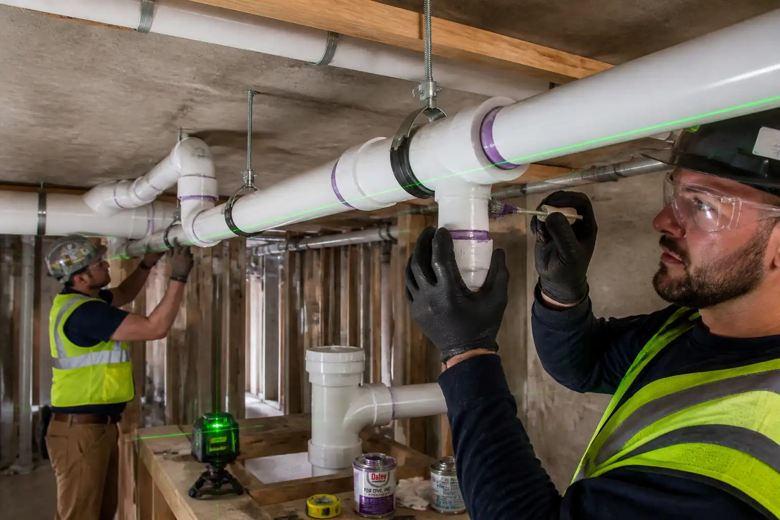

Method Statement: Installation of Internal uPVC Soil, Waste and Vent (DWV) Piping Networks – Method Statement
AI-assisted method statement with matching ITP, PDF download, and Excel export.
More than a static template
Unlike a downloadable Word or PDF template, this method statement is an AI-assisted editable starting point connected directly to a matching Inspection and Test Plan. Every section is structured, project-adaptable, and ready to export.
- AI-assisted drafting — Customize every section with AI for your specific project scope.
- Linked ITP — A matching inspection and test plan is generated alongside the method statement.
- Multiple export formats — Download as a formatted PDF or editable Excel spreadsheet.
- Editable starting point, not a final document — Review, verify, and adjust all content against your project requirements before use.
Static template vs. Quollnet workflow
| Feature | Static template | Quollnet |
|---|---|---|
| Project-specific content | Manual fill-in required | AI-assisted customization |
| Linked ITP | Separate document, no link | Matching ITP included |
| Export formats | Usually PDF only | PDF and Excel |
| Structured sections | Free-form layout | 13 standardized sections |
| Saved to your account | Local file only | Cloud-saved, reusable |
| Content accuracy | You verify everything | AI-assisted, you still verify |
| Cost | Often free but time-intensive | Free to customize and download |
What you can customize
When you save this method statement to your account, every section becomes editable. The following 13 sections are included:
- Scope — Defines the activity and its boundaries.
- References — Standards, specifications, and drawings.
- Responsibilities — Roles and accountabilities.
- Resources — Labour, plant, and equipment summary.
- Materials — Materials and compliance requirements.
- Equipment — Tools and equipment details.
- Prerequisites — Hold points and pre-conditions.
- Method sequence — Step-by-step construction sequence.
- Safety controls — HSE risk controls and PPE.
- Environmental controls — Environmental mitigation measures.
- QA/QC — Quality inspection and test requirements.
- ITP — Inspection and Test Plan table (has its own page).
- Attachments — Referenced drawings and documentation.
Why this method statement is used
This method statement is used to define and communicate the approved procedure for carrying out method statement: installation of internal upvc soil, waste and vent (dwv) piping networks on site. It ensures the work is planned in advance, the correct resources and controls are in place, and all personnel understand responsibilities, sequence, quality requirements, and safety controls before work begins. It aligns site execution with the documented scope and acceptance expectations.
Who uses this method statement
This method statement is used by contractors, site supervisors, project engineers, QA/QC engineers, HSE officers, consultants, and client representatives. It serves as a shared reference for planning, execution, supervision, inspection, and approval of the activity on site.
When it is prepared and submitted
The method statement is prepared before the work activity starts and submitted as part of the pre-construction documentation package for review and approval.
Who reviews or approves it
The method statement is usually submitted to the client representative, consultant, resident engineer, or project management consultant for review and approval before the work commences.
Important approval note
This method statement is an AI-assisted editable starting point, not a pre-approved document. Before use on any project, all content must be reviewed and approved by the relevant parties (superintendent, principal contractor, or client representative) in accordance with your contract and project quality plan.
For example: if your specification requires a departure from a referenced standard, that departure must be documented and approved separately — this method statement will not capture that automatically. Always verify against your applicable drawings, specifications, and regulatory requirements.
Method statement content
Scope
Work Summary
- Supply, installation, testing and commissioning of internal uPVC soil, waste and vent (DWV) pipework within the building, from fixture connections to main stacks and to the point of connection with the external network or stub-outs.
- Activities include: setting out, bracket/hanger installation, pipe cutting, deburring/chamfering, cleaning and solvent cement joint preparation, assembly, slope/alignment verification, branch fitting angle controls, cleanout (rodding eye) placement and accessibility, firestopping at penetrations, system testing, labeling, and as-built documentation.
Areas Covered
- Horizontal branches in ceiling voids and service shafts.
- Soil and waste stacks, vent stacks, and branch/vent connections.
- Penetrations through walls, floors, and fire/smoke barriers.
Exclusions
- External below-ground drainage (by others unless specified).
- Fixture traps and carrier assemblies outside uPVC scope.
- Acoustic wrapping and insulation unless specified.
Key Performance Requirements
- Leak-tight DWV system with verified hydraulic gradients.
- Correct branch fitting orientation and angles.
- Accessible cleanouts at prescribed intervals and changes of direction.
- Adequate support and allowance for thermal movement.
- Completion of water or air tests in accordance with approved ITP.
References
| Document Type | Reference / Number | Revision | Notes |
|---|---|---|---|
| Standard | BS EN 1329-1: Plastic piping systems for soil and waste discharge (low and high temperature) within buildings — PVC-U | Material and dimensional requirements for uPVC DWV pipes/fittings. | |
| Standard | BS EN 12056 (Parts 1–5): Gravity drainage systems inside buildings | System design, gradients, layout and testing guidance [Verify per project design]. | |
| Standard | ASTM D2665: Standard Specification for PVC Plastic Drain, Waste, and Vent Pipe and Fittings | Alternate material standard where ASTM specified. | |
| Standard | ASTM D2564: Solvent Cements for PVC Plastic Piping Systems | Jointing materials; follow manufacturer’s cure times. | |
| Standard | ASTM F656: Primers for Use in Solvent Cement Joints with PVC Pipe and Fittings | Use where primer is required by code/specification. | |
| Standard | ISO 1461: Hot dip galvanized coatings on fabricated iron and steel articles — Specifications and test methods | For steel hangers, brackets, and supports [Verify coating type per spec]. | |
| Code/Guideline | International Plumbing Code (IPC) / Uniform Plumbing Code (UPC) | Testing heads and air test pressures where local code adopts these [Verify per local code]. | |
| Project Document | Approved IFC drawings, technical specifications, schedules, and BIM coordination models | Governing project requirements. |
Responsibilities
| Role | Responsibility | Name / Party |
|---|---|---|
| Contractor MEP Site Engineer | Prepare and implement method statement, supervise works, coordinate inspections, and maintain records. | Contractor |
| Engineer/Consultant Representative | Review and approve materials, verify compliance with specs, witness hold points and final tests. | Engineer/Consultant |
| HSE Officer | Implement task-specific HSE controls, conduct toolbox talks, enforce permits, and monitor compliance. | Contractor |
| Plumbing Foreman/Technicians | Install pipework, perform cutting/jointing, set slopes, fittings, hangers, and supports. | Contractor |
| Firestopping Specialist | Ensure sleeves and firestopping systems are installed as per tested assemblies; maintain penetrations log. | Approved Subcontractor |
Resources
| Resource Type | Description | Quantity | Remarks |
|---|---|---|---|
| Personnel | 1 | ||
| Personnel | 1 | ||
| Personnel | 3–6 per gang [Verify per productivity plan] | ||
| Personnel | 1 |
Materials
| Material | Specification / Grade | Quantity | Remarks |
|---|---|---|---|
| uPVC DWV pipes (Socketed/plain ends) | PN rating per spec; color: grey/white [Verify] | ||
| uPVC DWV fittings | To match pipe system standard | ||
| PVC solvent cement | Medium/Heavy body as per diameter [Verify] | ||
| PVC primer/cleaner | Compatible with cement and pipe | ||
| Steel hangers, brackets, supports | Hot-dip galvanized to ISO 1461 or stainless [Verify] | ||
| Temporary test plugs/caps | Pressure-tight for water/air test [Verify] | ||
| Firestop sealants/collars/sleeves | Certified system matching substrate/annulus/rating [Verify] |
Equipment
| Equipment | Capacity / Type | Quantity | Inspection Required |
|---|---|---|---|
| Rotary laser level/digital inclinometer | ±0.1% accuracy or better | ||
| Cordless drill/driver & anchor setting tools | Suitable for M8–M12 anchors | ||
| Pipe cutter/saw and miter box | Cuts up to 160 mm OD | ||
| Deburring/chamfering tools | 10–15° bevel capability | ||
| Applicator daubers/brushes, rags | As per cement manufacturer | ||
| Water head test apparatus / standpipes | Up to 3.0 m head [Verify] | ||
| Air test kit & manometer | 0–50 kPa range, 0.1 kPa resolution |
Prerequisites
- Approved material submittals for uPVC pipes/fittings, solvent cement/primer, hangers, anchors, and firestop systems.
- Latest IFC drawings, coordinated services (BIM) model, and builder’s work drawings approved.
- Method statement and ITP approved by Engineer/Consultant.
- Permits/authorizations: Work at Height, Drilling/Anchoring, Hot Works (not typically required; only if ignition sources present), and Confined Space if applicable [Verify per project HSE plan and local regulations].
- Services scan/permit before drilling in structural elements to avoid embedded services and PT tendons.
- Anchor selection verified for base material, edge/spacing, design loads, and corrosion class; proof load test plan approved where required.
- Confirm access, scaffolds/ladders inspected (tagged), lighting and ventilation in ceiling voids adequate.
- SDS and manufacturer instructions for solvent cement/primer available; site personnel briefed on cure times and handling.
- Firestop details matched to openings (diameter, annular space, rating) and installer certified.
- Temporary protection for finishes installed; drip trays/absorbents available for solvent handling.
Method Sequence
| Step | Activity | Description | Responsibility | Inspection / Hold Point |
|---|---|---|---|---|
| 1 | Setting out and survey | Verify routes and elevations from IFC/coordinated drawings. Mark pipe centerlines, invert levels, cleanout positions, and hanger locations using laser level. Establish target gradients for each run. | MEP Site Engineer | Surveillance |
| 2 | Install hangers/anchors | Drill/percussive or hollow-bit dustless drill as per anchor system. Install drop-ins/channels/through-bolts. Fit threaded rods. Pre-set elevations for slope using laser and spacers. Do not fully tighten clamps to allow alignment. | Plumbing Foreman | Hold Point: Anchor layout prior to mass installation |
| 3 | Pipe cutting and end preparation | Measure and cut square using miter box/pipe cutter. Deburr ID/OD; chamfer spigot end 10–15° with 1–2 mm bevel (≤63 mm) and 2–3 mm (≥75 mm). Dry-fit to confirm insertion depth; mark spigot and socket for alignment and depth. | Installer | Random check each run |
| 4 | Cleaning and joint preparation | Ensure surfaces are clean, dry, and free of grease. Apply primer (where required by spec/code) uniformly to socket and spigot ends. Apply solvent cement per ASTM D2564 generously and evenly to both surfaces. | Installer | Witness for first 10 joints per shift |
| 5 | Assembly of joints | Immediately insert spigot fully into socket with 1/4 turn twist; align marks; hold for 30–45 s to prevent push-out. Wipe excess cement. For thermal movement, withdraw 5–10 mm after full insertion if system design requires expansion allowance [Verify]. | Installer | Surveillance |
| 6 | Slope and alignment control | Place assembled sections on hangers; adjust rod nuts to achieve design gradient. Use laser/digital level to verify every 2–3 m, at mid-spans and near changes of direction. Tighten clamps, leaving sliding supports for expansion; fix anchors at designated fixed points. | Installer/Site Engineer | Check each run |
| 7 | Branch fittings and angles | Install branches using 45° wyes or combination wye + 1/8 bend; use long-sweep 90° for horizontal-to-vertical transitions. Avoid short-radius 90° on horizontal-to-horizontal. Vent ties above centerline of drain. Maintain directional flow with swept fittings. | Installer | Hold Point: First-of-kind layout |
| 8 | Cleanouts (rodding eyes) | Install cleanouts at base of each stack, at ends of horizontal runs, and at changes of direction >45°. Provide accessibility via panels. Mark on as-builts and walls/ceilings. | Installer | Surveillance |
| 9 | Thermal movement accommodation | Provide fixed points at strategic locations (near changes in direction) and sliding supports elsewhere. Use expansion sockets/joints where required based on ΔL=α·L·ΔT with α≈0.06–0.08 mm/m·K for uPVC. Provide guides to prevent misalignment. | Site Engineer | Design check/Surveillance |
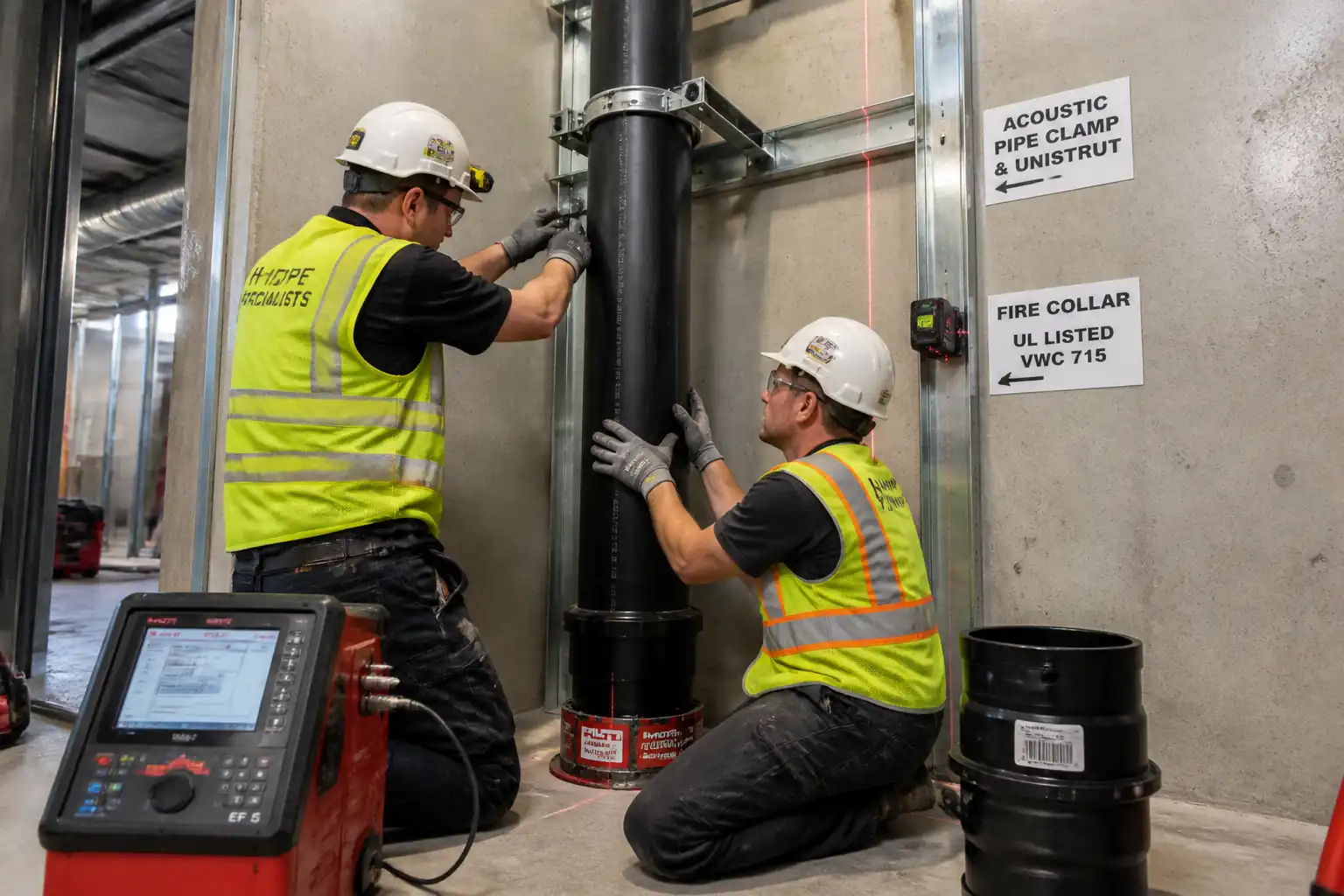
| 10 | Penetrations and firestopping | Install sleeves with annular space per firestop system. After pressure testing (if required by system), apply firestop collar/sealant per UL/ETA system. Label firestops and record. | Firestopping Specialist | Witness/hold per ITP |
| 11 | Curing before testing | Allow joints to cure undisturbed per cement manufacturer. Typical minimum: 1–2 h for handling; 24 h before water/air testing at 21°C and 50% RH. Increase for larger diameters/low temperature. | Installer | Surveillance |
| 12 | System testing (water or air) | Cap all openings. For water test, fill to required head from lowest point; hold and inspect. For air test, use low-pressure apparatus with calibrated manometer; soap test all joints. Follow HSE controls for pressure testing. | Site Engineer/Installer | Hold Point: Start and end of test |
| 13 | Functional flushing/commissioning | After structural closures, remove caps, flush lines from highest fixture stub-outs with clean water, verify free discharge, and check for ponding. Clean debris and reinstate caps until fixtures installed. | Installer | Surveillance |
| 14 | Identification and as-builts | Label stacks and cleanouts; update as-built drawings with pipe sizes, gradients, cleanout coordinates, and firestop IDs. Submit O&M manuals and warranties. | MEP Site Engineer | Final walkdown |
Health, Safety and Environment (HSE) – Safety Controls
Key Task-Specific Hazards and Controls
1) Hazard: Overhead drilling/anchoring into soffits
- Likely consequence: Struck-by falling concrete/dust; anchor failure; hit embedded rebar/PT tendon or live services.
- Engineering/procedural control: Use approved anchor system; perform service scan/permit to drill; use depth stop and hollow-bit vacuum drilling to reduce dust; maintain edge/spacings; proof load tests where specified.
- PPE: Safety helmet with chin strap, safety glasses, cut-resistant gloves, hearing protection, FFP2/FFP3 respirator for dust.
- Collective preventive measure: Mobile tower/scaffold with guardrails; debris catch trays; exclusion zone beneath.
- Inspection/permit/supervision: Daily scaffold/ladder tag; drilling permit; supervision by Site Engineer; HSE inspection.
2) Hazard: Working at height in ceiling voids
- Likely consequence: Falls, musculoskeletal injury.
- Engineering/procedural control: Use compliant podiums/towers; maintain three points of contact on ladders for short-duration tasks only; tool lanyards; avoid overreaching; move platform frequently.
- PPE: Full-body harness if fall arrest required, non-slip safety boots.
- Collective preventive measure: Platform with toe boards/rails; spotter in congested areas.
- Inspection/permit/supervision: Work at Height permit; pre-use inspection of access equipment; competent erectors.
3) Hazard: Solvent cement/primer vapors (flammable VOCs)
- Likely consequence: Dizziness, respiratory irritation; fire/explosion near ignition sources; skin/eye irritation.
- Engineering/procedural control: Use in well-ventilated areas; forced ventilation in confined voids; no ignition sources; decant minimal quantities; close containers immediately; follow SDS; use intrinsically safe lighting where applicable.
- PPE: Nitrile gloves, splash goggles, flame-resistant coveralls if specified, organic vapor respirator if ventilation inadequate [Verify per project HSE plan and local regulations].
- Collective preventive measure: Spill kits and absorbents; designated solvent handling area.
- Inspection/permit/supervision: Chemical handling briefing; SDS on site; flammability risk assessment; hot work permit if any ignition source present.
4) Hazard: Manual handling of pipe bundles and long sections
- Likely consequence: Strains, crush injuries.
- Engineering/procedural control: Team lifts; use pipe trolleys; break down bundles; plan lift routes; store at waist height where possible.
- PPE: Gloves, safety boots.
- Collective preventive measure: Mechanical aids; clear walkways.
- Inspection/permit/supervision: Manual handling training; supervisor oversight.
5) Hazard: Cutting/deburring operations
- Likely consequence: Lacerations, flying chips, eye injury.
- Engineering/procedural control: Use guarded tools; secure pipe in miter box; cut away from body; maintain blades.
- PPE: Cut-resistant gloves, goggles/face shield.
- Collective preventive measure: Designated cutting area with screens.
- Inspection/permit/supervision: Tool inspections; competency verification.
6) Hazard: Pressure testing (water or air)
- Likely consequence: Pipe or cap blow-off causing impact injuries.
- Engineering/procedural control: Use purpose-made test plugs rated for test pressure; gradual pressurization; barricade zone; never stand in line with caps; limit air tests to code requirements and lowest safe pressure; vent safely.
- PPE: Eye/face protection, gloves, helmet.
- Collective preventive measure: Exclusion zone and signage.
- Inspection/permit/supervision: Test permit; calibrated gauges; Engineer witness per ITP.
7) Hazard: Fire barrier penetrations
- Likely consequence: Compromised compartmentation and life safety.
- Engineering/procedural control: Only approved firestop systems; trained installers; maintain annular space; label and log.
- PPE: Gloves, goggles, suitable masks for sealant fumes.
- Collective preventive measure: Fire watch if hot works nearby.
- Inspection/permit/supervision: Firestopping inspection checklist; third-party witness if required.
8) Hazard: Noise/vibration from drills
- Likely consequence: Hearing damage; nuisance to occupants.
- Engineering/procedural control: Low-vibration techniques; schedule noisy works off-hours.
- PPE: Hearing protection.
- Collective preventive measure: Acoustic barriers where practicable.
- Inspection/permit/supervision: Noise monitoring if required.
Environmental Controls
- VOC Emissions: Use low-VOC cement where available; ensure ventilation; keep containers closed; avoid bulk decanting.
- Solvent Spills: Use drip trays; store chemicals in bunded area; provide spill kits; dispose of absorbents as hazardous waste per local rules [Verify per project HSE plan and local regulations].
- Plastic Waste/Offcuts: Segregate uPVC offcuts and send to approved recycler; avoid contamination with food/general waste.
- Dust from Drilling/Cutting: Use hollow-bit extraction or wet suppression; clean with HEPA vacuum (no dry sweeping).
- Noise: Schedule high-noise activities off-hours; maintain equipment; use acoustic shields if necessary.
- Water Testing Discharge: Discharge test water to sanitary drainage, not storm; strain debris before discharge; prevent flooding of occupied areas.
- Packaging: Return pallets; compact cardboard/plastic for recycling.
- Resource Efficiency: Pre-cut lengths off-site where feasible; optimize support spacing to minimize steel usage without compromising design.
QA/QC
Submittals and Records
- Material approvals: uPVC pipes/fittings, cement/primer, hangers/anchors, firestop systems (data sheets, compliance certificates).
- Method Statement and ITP approval prior to works.
- Calibration certificates for laser levels and manometers.
- Batch numbers of solvent cement/primer logged by area.
- Anchor proof load test results (if specified).
- Inspection checklists for joints, slopes, cleanouts, and branch configurations.
- Pressure/water test certificates with photos of gauges/heads.
- Firestop inspection forms and system IDs.
- As-built drawings with gradients, cleanout locations, and firestop references.
Tolerances/Acceptance
- Slope within target ±0.2% or ±3 mm per 1 m; no backfalls [Verify per project specifications].
- Pipe cut squareness within ±1 mm per 100 mm diameter; correct chamfer.
- Support spacing typical: 32–50 mm pipes ≤1.2 m; 75–110 mm pipes ≤1.5–2.0 m; vertical stacks at base and at each floor or ≤2.5 m [Verify per spec/manufacturer].
- Cleanout spacing ≤12–15 m on mains and at direction changes >45°; clearance ≥450 mm.
- Fittings: long-sweep/45° wyes used as required; no short 90° on horizontal-to-horizontal.
- Firestopping: Installed strictly to certified system and labeled.
Nonconformance and Corrections
- Record NCRs for leaks, backfalls, wrong fittings, inaccessible cleanouts, or anchor noncompliance. Rectify and retest affected sections.
- Replace any joint showing witness cracks, softening, or misalignment; re-cut and re-joint, do not re-solvent previously bonded joints.
Training/Competency
- Toolbox talks on solvent handling, safe drilling, and pressure testing before start.
- Only trained installers authorized to make solvent cement joints.
Attachments
- Manufacturer data sheets and SDS for solvent cement/primer.
- Anchor technical data sheets and approvals (ETA/ICC) with load tables.
- Typical details: hanger spacing, expansion details, branch and cleanout configurations.
- Firestop system drawings (UL/ETA) and installation instructions.
- Setting-out and slope verification checklist template.
- Jointing inspection checklist template.
- Pressure/water test certificate template.
- As-built drawing mark-up examples.
This content is a read-only public reference. Download or customize to get an editable version.
ITP preview
The first inspection activities from the linked ITP for Method Statement: Installation of Internal uPVC Soil, Waste and Vent (DWV) Piping Networks:
| Activity | Inspection / Test | Acceptance Criteria | Responsibility | Record |
|---|---|---|---|---|
| Material receipt and identification | Verify standards, sizes, markings; review COC and SDS | Conformity to BS EN 1329-1/ASTM D2665; no damage/warping; correct batches logged | Contractor QA/QC; Witness by Engineer | Material inspection report, photos |
| Anchor/hanger layout and installation | Check spacing, edge distances, embedment, torque | Per manufacturer data and project design; corrosion class correct | Contractor; Witness by Engineer | Anchor/hanger inspection checklist, torque log |
| Anchor proof load test (if required) | Apply proof load (e.g., 1.5× service load for 15 s) to sample anchors [Verify] | No pull-out or displacement >1 mm; no substrate cracking | Contractor with third-party if specified; Witness by Engineer | Pull test certificates |
Showing 3 of 11 inspection activities. View full ITP →
Related Inspection and Test Plan
An Inspection and Test Plan (ITP) is available for Method Statement: Installation of Internal uPVC Soil, Waste and Vent (DWV) Piping Networks. The ITP defines the inspection activities, acceptance criteria, hold and witness points, responsible parties, and records required to verify the work described in this method statement.
View the Method Statement: Installation of Internal uPVC Soil, Waste and Vent (DWV) Piping Networks ITP →Frequently asked questions
Continue with related Quollnet resources connected to this method statement.