Method Statement: Installation of Gravity uPVC and HDPE Sewer Pipelines in Excavated Trenches – Method Statement
AI-assisted method statement with matching ITP, PDF download, and Excel export.
More than a static template
Unlike a downloadable Word or PDF template, this method statement is an AI-assisted editable starting point connected directly to a matching Inspection and Test Plan. Every section is structured, project-adaptable, and ready to export.
- AI-assisted drafting — Customize every section with AI for your specific project scope.
- Linked ITP — A matching inspection and test plan is generated alongside the method statement.
- Multiple export formats — Download as a formatted PDF or editable Excel spreadsheet.
- Editable starting point, not a final document — Review, verify, and adjust all content against your project requirements before use.
Static template vs. Quollnet workflow
| Feature | Static template | Quollnet |
|---|---|---|
| Project-specific content | Manual fill-in required | AI-assisted customization |
| Linked ITP | Separate document, no link | Matching ITP included |
| Export formats | Usually PDF only | PDF and Excel |
| Structured sections | Free-form layout | 13 standardized sections |
| Saved to your account | Local file only | Cloud-saved, reusable |
| Content accuracy | You verify everything | AI-assisted, you still verify |
| Cost | Often free but time-intensive | Free to customize and download |
What you can customize
When you save this method statement to your account, every section becomes editable. The following 13 sections are included:
- Scope — Defines the activity and its boundaries.
- References — Standards, specifications, and drawings.
- Responsibilities — Roles and accountabilities.
- Resources — Labour, plant, and equipment summary.
- Materials — Materials and compliance requirements.
- Equipment — Tools and equipment details.
- Prerequisites — Hold points and pre-conditions.
- Method sequence — Step-by-step construction sequence.
- Safety controls — HSE risk controls and PPE.
- Environmental controls — Environmental mitigation measures.
- QA/QC — Quality inspection and test requirements.
- ITP — Inspection and Test Plan table (has its own page).
- Attachments — Referenced drawings and documentation.
Why this method statement is used
This method statement is used to define and communicate the approved procedure for carrying out method statement: installation of gravity upvc and hdpe sewer pipelines in excavated trenches on site. It ensures the work is planned in advance, the correct resources and controls are in place, and all personnel understand responsibilities, sequence, quality requirements, and safety controls before work begins. It aligns site execution with the documented scope and acceptance expectations.
Who uses this method statement
This method statement is used by contractors, site supervisors, project engineers, QA/QC engineers, HSE officers, consultants, and client representatives. It serves as a shared reference for planning, execution, supervision, inspection, and approval of the activity on site.
When it is prepared and submitted
The method statement is prepared before the work activity starts and submitted as part of the pre-construction documentation package for review and approval.
Who reviews or approves it
The method statement is usually submitted to the client representative, consultant, resident engineer, or project management consultant for review and approval before the work commences.
Important approval note
This method statement is an AI-assisted editable starting point, not a pre-approved document. Before use on any project, all content must be reviewed and approved by the relevant parties (superintendent, principal contractor, or client representative) in accordance with your contract and project quality plan.
For example: if your specification requires a departure from a referenced standard, that departure must be documented and approved separately — this method statement will not capture that automatically. Always verify against your applicable drawings, specifications, and regulatory requirements.
Method statement content
Scope
Overview
This method statement covers the supply, handling, installation, and inspection/testing of gravity uPVC and HDPE sewer pipelines in excavated trenches from manhole to manhole, including:
- Trench bed preparation and granular bedding
- Pipe stringing, inspection, and laser-controlled laying to line and grade
- Socket jointing with elastomeric rubber rings and approved lubricant
- Initial sidefill and backfill to 300 mm above pipe crown
- Deflection monitoring of thermoplastic pipes (mandrel/CCTV)
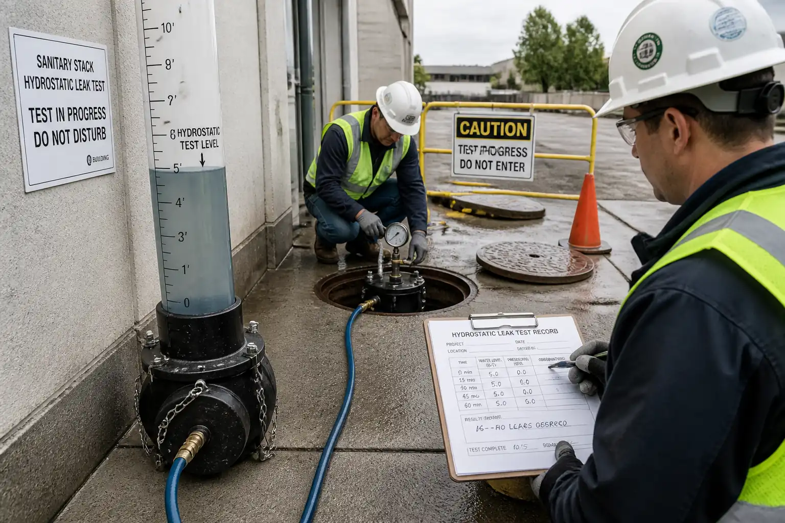
- Hydrostatic testing (water exfiltration/infiltration) of installed pipelines and connections
Inclusions
- Compliance with referenced standards and approved shop drawings
- Handover records including as-built invert levels, test certificates, and QA/QC documentation
Exclusions
- Deep excavation, shoring design/installation, dewatering systems beyond maintaining a dry trench during laying [Verify per project scope]
- Construction of manholes and final carriageway reinstatement (unless noted otherwise)
Key Performance Requirements
- Pipe installation to specified line and grade; no over-excavation or point loading
- Joints to be fully home with marked insertion depth and free from visible defects
- Compaction of embedment/backfill to specified density without damaging the pipe
- Deflection within allowable limits; hydrostatic test pass to applicable standard
- HSE controls for trench work, lifting, confined spaces, and water testing [Verify per project HSE plan and local regulations]
References
| Document Type | Reference / Number | Revision | Notes |
|---|---|---|---|
| Standard | EN 1610: Construction and testing of drains and sewers | Primary reference for bedding classes, leakage/pressure for water/air tests, and acceptance criteria. | |
| Standard | BS EN 1401-1: PVC-U piping systems for non-pressure underground drainage and sewerage | Pipe material, dimensions, stiffness (e.g., SN4/SN8). [Verify per project specifications]. | |
| Standard | EN 12666-1: Plastics piping systems for non-pressure underground drainage and sewerage — Polyethylene (PE) | For solid wall HDPE gravity sewers. Alternative: EN 13476 for structured-wall systems. | |
| Standard | EN 681-1: Elastomeric seals — Requirements for water and drainage applications | Type WC or as specified for underground drainage. | |
| Standard | ASTM F1417: Installation Acceptance of Plastic Gravity Sewer Lines Using Low-Pressure Air | Provided for reference where air testing is permitted by authority. Project requires hydrostatic testing unless otherwise approved. | |
| Standard | ASTM C969/C969M: Infiltration/Exfiltration Acceptance Testing of Installed Sewer Lines | Alternative acceptance method where specified. | |
| Standard | ASTM D698/D1557: Laboratory Compaction Characteristics of Soil | Determine MDD/OMC for field density control. | |
| Standard | ASTM D6938: In-Place Density and Water Content of Soil by Nuclear Methods | Or ASTM D1556 sand-cone as alternative. | |
| Standard | ISO 17123 (relevant parts) — Optical and electronic instruments field procedures | Calibration/verification for laser level/total station. |
Responsibilities
| Role | Responsibility | Name / Party |
|---|---|---|
| Construction Manager | Contractor | |
| QA/QC Engineer | Contractor | |
| Land Surveyor | Contractor | |
| Site Engineer / Foreman (Pipelaying) | Contractor | |
| HSE Manager / Officer | Contractor | |
| Independent Laboratory / Specialist | Approved Third Party | |
| Client/Engineer | Engineer |
Resources
| Resource Type | Description | Quantity | Remarks |
|---|---|---|---|
| Labor | Pipe layers, helpers | 1 crew | |
| Labor | Surveyor with assistant | 1 team | |
| Labor | Excavator, compactor operators | As required | |
| Staff | QA/QC Engineer, HSE Officer | 1 each |
Materials
| Material | Specification / Grade | Quantity | Remarks |
|---|---|---|---|
| PVC-U pipe | DN 110–600 as per drawings [Verify] | ||
| HDPE pipe | DN as per drawings [Verify] | ||
| Rubber gaskets | Manufacturer approved | ||
| Pipe lubricant | Per pipe supplier | ||
| Bedding material | Grading per project specs [Verify] | ||
| Warning tape | Color/wording per authority |
Equipment
| Equipment | Capacity / Type | Quantity | Inspection Required |
|---|---|---|---|
| Tracked excavator (13–21 t) | As required | ||
| Pipe laser (IP68) | 1 set | ||
| Vibratory plate/rammer | As required | ||
| Rigid/rollable mandrel with 9 arms | 1 set | ||
| Water testing apparatus | 1 set | ||
| Crawler/Push camera | As required | ||
| Total station/Level | 1 set |
Prerequisites
- Approved shop drawings, line/level schedule, and this Method Statement with ITP.
- Confirm utility clearances and permits; valid excavation/trench and confined space permits [Verify per project HSE plan and local regulations].
- Trench excavation complete to correct width and depth with safe side support (shoring/benching) as per design.
- Dewatering in place to keep trench dry; groundwater level below pipe invert by ≥ 300 mm during laying [Verify].
- Laboratory approvals for bedding material gradation and compaction criteria (MDD/OMC from ASTM D698 or D1557).
- Material inspection: pipes, gaskets, lubricant; check certificates of compliance to BS EN/EN standards.
- Equipment calibration: pipe laser, pressure gauge, flow meter (if used) — valid certificates.
- Weather check: avoid laying during heavy rain or when temperature outside manufacturer’s jointing limits [Verify].
- Hold/Witness coordination with Engineer for bedding approval and testing notifications (≥24–48 hr notice [Verify]).
Method Sequence
| Step | Activity | Description | Responsibility | Inspection / Hold Point |
|---|---|---|---|---|
| 1 | Pre-setout and trench verification | Verify trench alignment, width, and depth. Ensure minimum side clearance ≥ 150 mm each side of pipe OD [Verify]. Trim bed to uniform grade without high points. | Site Engineer / Surveyor | Visual and survey check |
| 2 | Bedding placement and approval | Place and level granular bedding to minimum 100 mm thickness (or as specified). Grade using pipe laser datum. Lightly compact to firm support (do not over-compact). Form bell holes at joints to avoid point load. | Foreman / QA/QC | Engineer Witness/Hold as specified |
| 3 | Pipe inspection and preparation | Inspect pipes/gaskets for damage and cleanliness. Confirm chamfer and insertion depth mark. Fit clean, undamaged EN 681-1 gaskets. Lubricate spigot per manufacturer. | Foreman / QA/QC | Visual |
| 4 | Laying and jointing to laser line/grade | Start upstream from manhole; place pipe with socket facing upstream. Align with pipe laser target. Push spigot into socket until insertion mark flush with socket face. For angular deflection at joints, do not exceed manufacturer limit (typically 1–3° for PVC-U; 3–5° for HDPE couplers) [Verify]. | Pipe Laying Crew / Surveyor | Continuous supervision |
| 5 | Connection to manholes/structures | Cut pipe square; deburr and chamfer. Install flexible couplers/boots as detailed. Seal wall penetrations with specified method (e.g., puddle flange/Link-seal) [Verify]. | Site Engineer | Engineer Witness |
| 6 | Initial sidefill and haunching | Place granular sidefill symmetrically in 150 mm layers from springline upward, hand-tamping under haunches to eliminate voids. Do not displace pipe. | Foreman | QA/QC spot checks |
| 7 | Cover to 300 mm above crown (initial backfill) | Continue placing approved material in 150 mm lifts to at least 300 mm above crown. Compact using light equipment. Maintain trench free of standing water. | Foreman | QA/QC |
| 8 | Deflection monitoring (thermoplastic pipes) | After minimum 30 days from backfilling (or as specified), perform mandrel test or CCTV/laser profiling. Mandrel diameter: 95% of nominal ID for PVC-U (allowable deflection ≤ 5%); for HDPE, use specified limit (commonly ≤ 7.5%) and corresponding mandrel diameter (≥ 92.5% ID) [Verify]. | QA/QC / Specialist | Engineer Witness |
| 9 | Hydrostatic testing (water exfiltration/infiltration) | Seal test section between manholes with plugs. Fill pipeline slowly from low end, venting air at high points. Soak/gasket conditioning ≥ 2 hours (or per spec). Establish test pressure (static head) typically 10 kPa (100 mbar) at pipe crown; maintain for 30 minutes [Verify per EN 1610/project specs]. Measure water loss. | QA/QC / Specialist | Engineer Witness (Hold) |
| 10 | Restoration and protection | Install warning tape as specified. Protect open ends with caps. Maintain as-built records of inverts/chainages. | Site Engineer | QA/QC |
Health, Safety and Environmental Controls — Task-Specific Safety
Key Hazards and Controls
- Hazard: Trench collapse (excavation >1.2 m)
- Likely consequence: Fatal crush injuries, entrapment
- Engineering/procedural control: Install shoring/trench boxes or batter to safe slope; keep spoil ≥ 0.6 m from edge; daily inspection by Competent Person; control access with barriers
- Required PPE: Safety helmet, high-vis vest, safety boots, gloves
- Collective preventive measure: Physical trench support systems, edge protection, safe access ladders every 7–10 m
-
Inspection/permit/supervision: Daily excavation inspection checklist; Excavation/Trench Permit [Verify per project HSE plan and local regulations]; Competent Person sign-off
-
Hazard: Underground utility strike
- Likely consequence: Electrocution, flooding, gas leak
- Engineering/procedural control: Review utility maps; CAT and Genny scan; trial holes/hand-dig near utilities; set exclusion zones
- PPE: Dielectric gloves (if required), eye protection
- Collective measure: Permit-to-dig system; tagging/marking of utilities
-
Inspection/permit/supervision: Permit-to-dig; HSE Officer oversight
-
Hazard: Lifting/handling of pipes and plugs
- Likely consequence: Crush injuries, dropped loads
- Engineering/procedural control: Certified lifting gear and slings; use spreader bars for large diameters; tag lines; no standing under loads
- PPE: Helmets with chin strap, gloves, steel-toe boots
- Collective measure: Appointed Rigger/Signaller; lifting plan and exclusion zones
-
Inspection/permit/supervision: Pre-use inspection of lifting gear; crane/telehandler inspection certificates; Lifting Permit
-
Hazard: Working in or near confined spaces (manholes during testing)
- Likely consequence: Asphyxiation, toxic exposure, drowning
- Engineering/procedural control: Gas monitoring (O2, H2S, CO, CH4) before and during entry; forced ventilation; top-man and retrieval system; limit entry during filling/draining
- PPE: Harness with retrieval line, gas detector, gloves, eye protection
- Collective measure: Confined Space Entry Permit; rescue plan and equipment on site
-
Inspection/permit/supervision: Permit sign-off by Authorized Person; equipment calibration logs
-
Hazard: Pressurization during hydrostatic test (plugs/hoses)
- Likely consequence: Plug ejection causing impact injuries
- Engineering/procedural control: Use rated test plugs with safety chains; secure against movement; gradual pressurization; establish exclusion zone; never stand in line with plugs
- PPE: Helmets, eye/face protection, gloves
- Collective measure: Barriers and signage; supervisor control of valves
-
Inspection/permit/supervision: Verify plug rating and gauge calibration; Test Permit; Engineer witness
-
Hazard: Slips, trips, and falls in trench
- Likely consequence: Sprains, fractures
- Engineering/procedural control: Maintain dry, tidy trench; provide safe walkways/ramps; adequate lighting for night work
- PPE: Slip-resistant boots, headlamp (if low light)
- Collective measure: Housekeeping program; dedicated access points
-
Inspection/permit/supervision: Daily HSE inspection
-
Hazard: Noise and vibration (compaction equipment)
- Likely consequence: Hearing loss, hand-arm vibration
- Engineering/procedural control: Use low-vibration tools; limit exposure time; rotate tasks
- PPE: Hearing protection
- Collective measure: Noise mapping and zoning
-
Inspection/permit/supervision: HAVS records; equipment maintenance logs
-
Hazard: Manual handling (gaskets, small pipes)
- Likely consequence: Musculoskeletal injuries
- Engineering/procedural control: Team lifts; use trolleys; manual handling training
- PPE: Back support belts (if approved), gloves
- Collective measure: Mechanical aids prioritized
-
Inspection/permit/supervision: Supervisor monitoring and training records
-
Hazard: Water ingress/flooding of trench
- Likely consequence: Drowning, collapse risk increase
- Engineering/procedural control: Dewatering pumps with standby; weather monitoring; stop works in heavy rain; emergency egress points
- PPE: Waterproof boots, life jacket where flooding risk exists
- Collective measure: Pump alarms/backup power
-
Inspection/permit/supervision: Dewatering plan; daily checks
-
Hazard: Exposure to sewage during tie-ins
- Likely consequence: Infection, illness
- Engineering/procedural control: Isolate flows; disinfect area; hygiene facilities and vaccinations as required
- PPE: Chemical-resistant gloves, eye protection, coveralls
- Collective measure: Task-specific method and sanitation plan
- Inspection/permit/supervision: Permit to work; HSE oversight
Environmental Controls
- Sediment and dewatering control: Discharge only via approved silt control (sediment tanks, filters) to prevent turbidity; no direct discharge to surface waters. Monitor pH and turbidity if required [Verify].
- Wastewater from hydrostatic testing: Dechlorinate (if potable source) and discharge at low velocity through energy dissipation to approved outfall. Record volume and quality parameters as required [Verify].
- Spill prevention: Secondary containment for fuels/lubricants; refuel away from trenches/watercourses; spill kits on site; report and clean up immediately.
- Material storage: Store pipes on padded supports; cap ends to keep out debris; cover gaskets and lubricants from sun/contaminants.
- Noise/dust: Wet down haul roads; speed limits; maintain equipment; restrict high-noise operations to permitted hours.
- Soil management: Segregate topsoil/subsoil; reuse approved spoil where permitted; dispose of surplus to licensed facility with transfer notes.
- Wildlife/vegetation: Protect trees/roots with fencing; no storage within root protection zones [Verify].
- Nuisance control: Keep site tidy, control lighting spill, and provide community notifications if required.
Quality Assurance and Quality Control
Controls and Records
- Approvals: Manufacturer data sheets, material compliance certificates (EN/BS/ISO), calibration certificates.
- Incoming inspection: Check pipe markings (standard, stiffness, DN, batch), gasket type, and condition; record in MIR.
- Tolerances: Invert level ±10 mm per manhole run; line deviation ≤ 10 mm; gradient deviation ≤ 6 mm in 30 m [Verify per project specifications].
- Bedding and embedment: Confirm material grading; thickness and compaction as specified. Field density testing frequency typically 1/50 m per layer per trench or minimum 1 per 250 m² per lift [Verify].
- Jointing QC: Insertion depth marks painted/verified each joint; random joint pull-back checks every 20 joints [Verify]; lubricant per manufacturer.
- Deflection testing: Conduct after minimum 30 days; acceptance ≤ 5% (PVC-U) and per spec for HDPE (commonly ≤ 7.5%) [Verify]. Record sections failing; plan remediation and retest.
- Hydrostatic testing: Follow EN 1610 procedures; soak time, pressure head, duration, temperature corrected; allowable leakage ≤ 0.15 L/m² wetted surface in 30 min [Verify].
- As-built surveys: Capture coordinates and inverts at each manhole and at ≤25 m intervals, including bends and connections.
- ITP compliance: Hold/Witness points for bedding approval, first joint, testing, and final acceptance.
- Documentation: MIRs, inspection checklists, compaction/FDT reports, deflection/CCTV reports, hydrostatic test certificates, as-built drawings.
Nonconformance and Corrective Action
- Document NCRs for any tolerance/test failures; propose corrective action (e.g., re-bed, re-compact, replace joint, re-round pipe), obtain Engineer approval, and retest.
Attachments
- Approved shop drawings and alignment/longitudinal profile
- Manufacturer installation manuals (uPVC/HDPE pipes, gaskets, couplers)
- Lifting plan and certificates for slings/shackles
- Calibration certificates for laser, gauges, gas detectors
- Trench/excavation and confined space permits (templates)
- Bedding material sieve analysis and compaction criteria (MDD/OMC)
- Sample inspection checklists and test report templates (laying log, FDT, deflection, hydrostatic)
- Risk assessment and environmental management plan for sewer laying
This content is a read-only public reference. Download or customize to get an editable version.
ITP preview
The first inspection activities from the linked ITP for Method Statement: Installation of Gravity uPVC and HDPE Sewer Pipelines in Excavated Trenches:
| Activity | Inspection / Test | Acceptance Criteria | Responsibility | Record |
|---|---|---|---|---|
| Bedding material approval | Visual, gradation test (1 per source/lot) | Meets specified grading; clean, angular/rounded as permitted; no deleterious material | QA/QC Engineer / Engineer | MIR, Sieve analysis report |
| Trench bed level and condition | Laser/level check at 5–10 m intervals [Verify] | Level within ±10 mm; firm, no standing water; bell holes prepared | Site Engineer / Engineer | Pre-lay inspection form, survey log |
| First pipe jointing (benchmark) | Witness joint assembly and insertion depth verification | Insertion mark flush; gasket seated; no visible damage | Foreman / QA/QC / Engineer | Jointing checklist |
Showing 3 of 9 inspection activities. View full ITP →
Related Inspection and Test Plan
An Inspection and Test Plan (ITP) is available for Method Statement: Installation of Gravity uPVC and HDPE Sewer Pipelines in Excavated Trenches. The ITP defines the inspection activities, acceptance criteria, hold and witness points, responsible parties, and records required to verify the work described in this method statement.
View the Method Statement: Installation of Gravity uPVC and HDPE Sewer Pipelines in Excavated Trenches ITP →Frequently asked questions
Continue with related Quollnet resources connected to this method statement.