
Method Statement: Backfilling and Compaction of Sewer Trenches – Method Statement
AI-assisted method statement with matching ITP, PDF download, and Excel export.
More than a static template
Unlike a downloadable Word or PDF template, this method statement is an AI-assisted editable starting point connected directly to a matching Inspection and Test Plan. Every section is structured, project-adaptable, and ready to export.
- AI-assisted drafting — Customize every section with AI for your specific project scope.
- Linked ITP — A matching inspection and test plan is generated alongside the method statement.
- Multiple export formats — Download as a formatted PDF or editable Excel spreadsheet.
- Editable starting point, not a final document — Review, verify, and adjust all content against your project requirements before use.
Static template vs. Quollnet workflow
| Feature | Static template | Quollnet |
|---|---|---|
| Project-specific content | Manual fill-in required | AI-assisted customization |
| Linked ITP | Separate document, no link | Matching ITP included |
| Export formats | Usually PDF only | PDF and Excel |
| Structured sections | Free-form layout | 13 standardized sections |
| Saved to your account | Local file only | Cloud-saved, reusable |
| Content accuracy | You verify everything | AI-assisted, you still verify |
| Cost | Often free but time-intensive | Free to customize and download |
What you can customize
When you save this method statement to your account, every section becomes editable. The following 13 sections are included:
- Scope — Defines the activity and its boundaries.
- References — Standards, specifications, and drawings.
- Responsibilities — Roles and accountabilities.
- Resources — Labour, plant, and equipment summary.
- Materials — Materials and compliance requirements.
- Equipment — Tools and equipment details.
- Prerequisites — Hold points and pre-conditions.
- Method sequence — Step-by-step construction sequence.
- Safety controls — HSE risk controls and PPE.
- Environmental controls — Environmental mitigation measures.
- QA/QC — Quality inspection and test requirements.
- ITP — Inspection and Test Plan table (has its own page).
- Attachments — Referenced drawings and documentation.
Why this method statement is used
This method statement is used to define and communicate the approved procedure for carrying out method statement: backfilling and compaction of sewer trenches on site. It ensures the work is planned in advance, the correct resources and controls are in place, and all personnel understand responsibilities, sequence, quality requirements, and safety controls before work begins. It aligns site execution with the documented scope and acceptance expectations.
Who uses this method statement
This method statement is used by contractors, site supervisors, project engineers, QA/QC engineers, HSE officers, consultants, and client representatives. It serves as a shared reference for planning, execution, supervision, inspection, and approval of the activity on site.
When it is prepared and submitted
The method statement is prepared before the work activity starts and submitted as part of the pre-construction documentation package for review and approval.
Who reviews or approves it
The method statement is usually submitted to the client representative, consultant, resident engineer, or project management consultant for review and approval before the work commences.
Important approval note
This method statement is an AI-assisted editable starting point, not a pre-approved document. Before use on any project, all content must be reviewed and approved by the relevant parties (superintendent, principal contractor, or client representative) in accordance with your contract and project quality plan.
For example: if your specification requires a departure from a referenced standard, that departure must be documented and approved separately — this method statement will not capture that automatically. Always verify against your applicable drawings, specifications, and regulatory requirements.
Method statement content
Scope
Scope
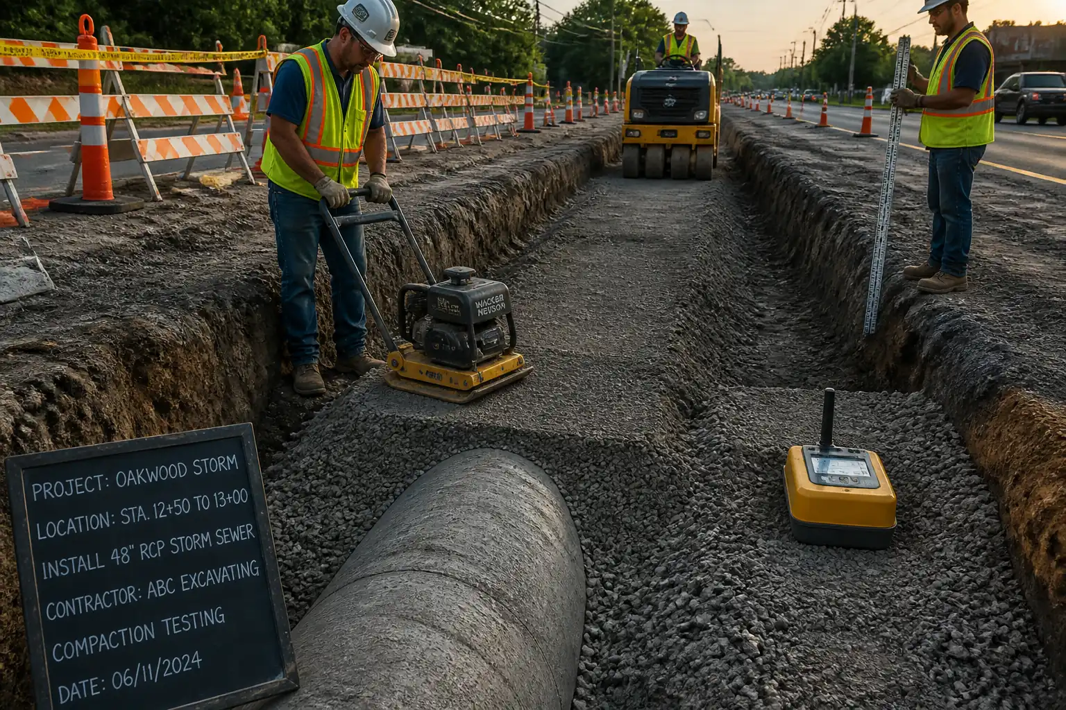
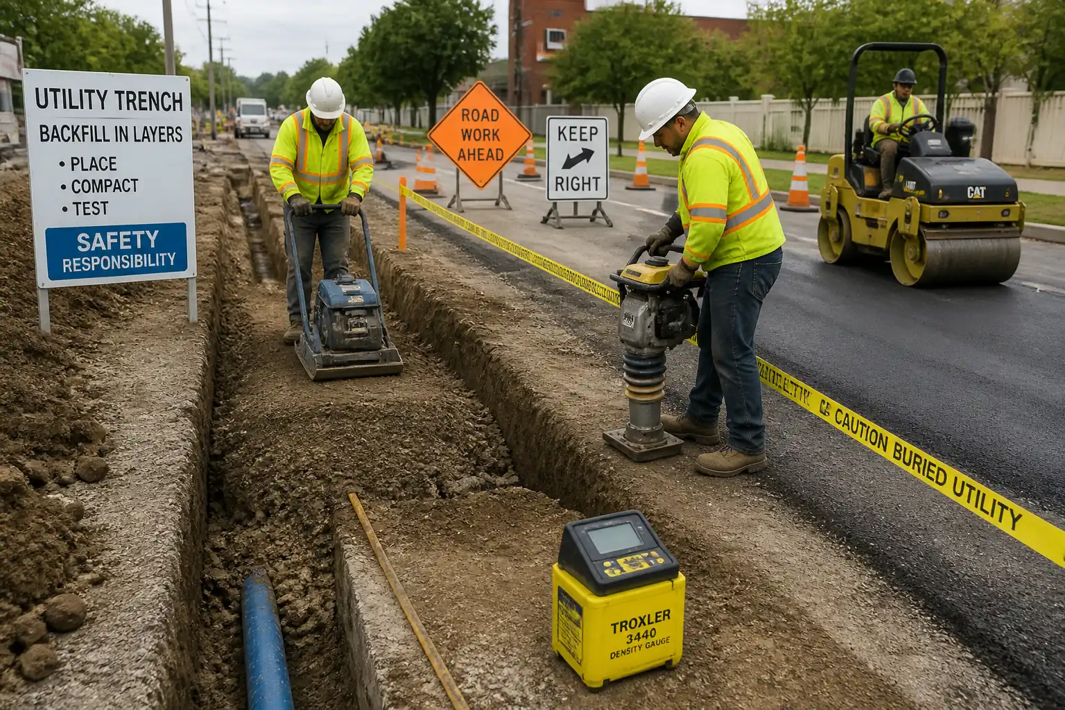
This method statement defines the procedures, resources, HSE controls, QA/QC checks, and inspection/testing requirements for the backfilling and compaction of sewer trenches following pipe installation. It includes:
- Selection and approval of trench backfill materials (bedding, haunch, initial backfill, and general backfill) and suitability of excavated material for reuse.
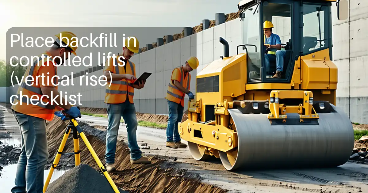
- Lift thickness control, moisture conditioning, and density targets per zone.
- Compaction equipment selection and limitations, particularly near flexible pipes (PVC/HDPE) to prevent pipe displacement or damage.
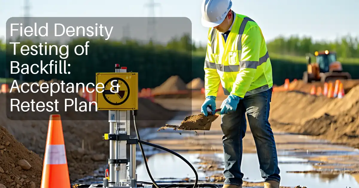
- Field density testing (nuclear gauge or sand-cone), test frequencies, and acceptance criteria.
- Prevention of pipe displacement and maintenance of line and grade during backfilling and compaction.
- Environmental protection, traffic and public interface controls, and documentation requirements.
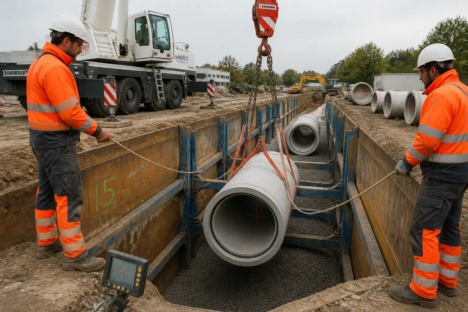
Works begin only after completion and acceptance of pipe installation in the trench section to be backfilled and confirmation that required inspections/permits are in place.
References
| Document Type | Reference / Number | Revision | Notes |
|---|---|---|---|
| ASTM | ASTM D2321 [Verify applicability] | Primary for PVC/HDPE flexible pipes | |
| ASTM | ASTM D698 / ASTM D1557 | Select per project specification (roadway vs non-traffic) | |
| ASTM | ASTM D6938 (Nuclear); ASTM D1556 (Sand-Cone); ASTM D2216 (Moisture, oven-dry) | ||
| ASTM/ISO | ASTM D6913/D6913M (Sieve); ASTM D7928 (Hydrometer); ISO 14688-1/2 (Soil identification) [Verify applicability] | ||
| ASTM | ASTM C1479 [If concrete pipe used] | ||
| ISO/BS/OSHA | BS EN 16228 (where applicable), OSHA 29 CFR 1926 Subpart P (Excavations) [Verify local equivalent] | Use local regulations where jurisdiction requires | |
| BS EN/ASTM | BS EN 13249 series / ASTM D4751, D4632 [Verify applicability] |
Responsibilities
| Role | Responsibility | Name / Party |
|---|---|---|
| Project Manager | Project Manager | Contractor |
| Site Engineer | Site Engineer | Contractor |
| QA/QC Engineer | QA/QC Engineer | Contractor |
| HSE Manager | HSE Manager | Contractor |
| Surveyor | Surveyor | Contractor |
| Foreman | Foreman | Contractor |
| Lab Technician | Independent Laboratory | Third Party |
Resources
| Resource Type | Description | Quantity | Remarks |
|---|---|---|---|
| Personnel | Project Manager, Site Engineer, QA/QC Engineer, HSE Officer, Surveyor, Foreman | As required | |
| Personnel | Skilled operators, compactors, laborers, flagmen/banksman | 8–16 per crew [Verify per productivity] |
Materials
| Material | Specification / Grade | Quantity | Remarks |
|---|---|---|---|
| Granular bedding | [Project Spec] | As per trench volume | |
| Selected granular fill | [Project Spec] | As required | |
| Common fill | [Project Spec] | As required | |
| Geotextile | [Project Spec] | As required | |
| Detectable warning tape (if required) | [Project Spec] | As required | |
| Water | [Project Spec] | As required |
Equipment
| Equipment | Capacity / Type | Quantity | Inspection Required |
|---|---|---|---|
| 20–30 t class | 1–2 | Yes | |
| 70–150 kg | 2–3 | Yes | |
| 60–80 kg | 1–2 | Yes | |
| 1–2 t | 1 | Yes | |
| 1 set | Yes | ||
| 1 set | Yes | ||
| As required | Yes | ||
| As required | Yes |
Prerequisites
Pre-start requirements
- Approved IFC drawings, trench typical sections, and specifications.
- Permit to Excavate/Permit to Work issued; utility clearance completed with marked services. [Verify per project HSE plan and local regulations]
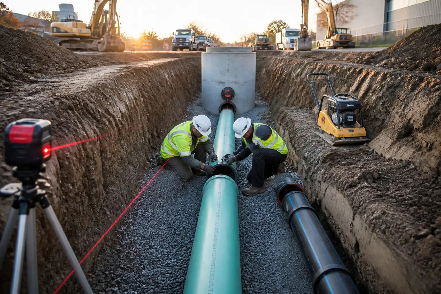
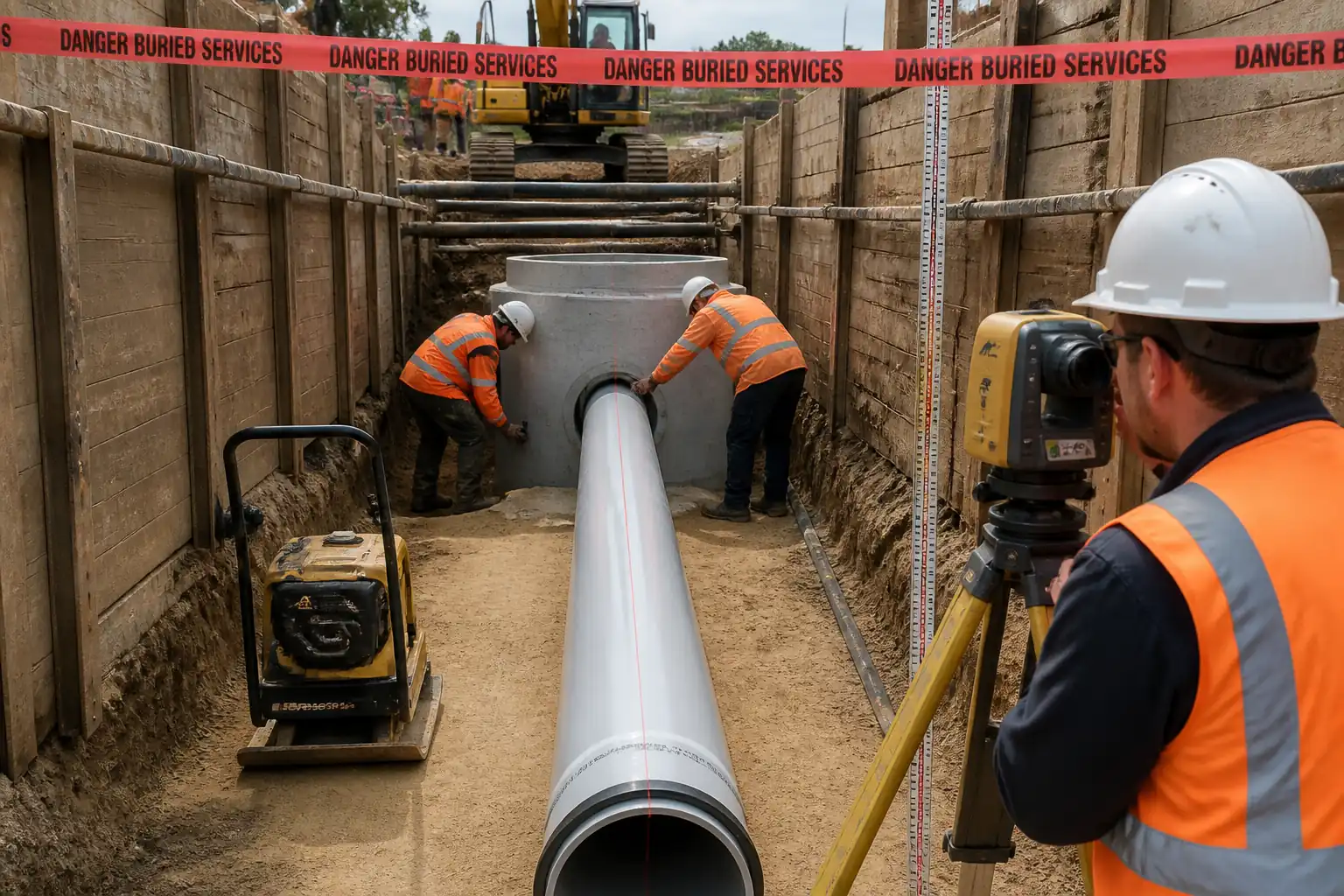
- Pipe installation of the section completed and preliminarily accepted for line, level, jointing, and bedding.
- Material approvals and laboratory Proctor curves (ASTM D698 and/or D1557) for each backfill type.
- Compaction trial (if required by spec) to validate equipment, lift thickness, and passes.
- Field testing agency engaged; nuclear gauge/sand-cone equipment calibrated; operator certifications in date.
- HSE documentation: Task risk assessment, lifting plan (if applicable), dewatering plan, traffic management plan, and toolbox talk completed.
- Inspection/Test Plan (ITP) approved; Hold/Witness points communicated to all parties.
Method Sequence
| Step | Activity | Description | Responsibility | Inspection / Hold Point |
|---|---|---|---|---|
| 1 | Pre-backfill inspection (Hold Point) | Confirm pipe alignment/level, joint integrity, bedding thickness/grade, trench support, and dewatering effectiveness. Record invert levels and gradient. | Site Engineer/Surveyor + Client Rep | Survey check; visual |
| 2 | Bedding top-up/repair (if required) | Place/trim bedding to full support under pipe. Avoid bridging; use hand tools to fill voids under haunch. | Foreman | Visual |
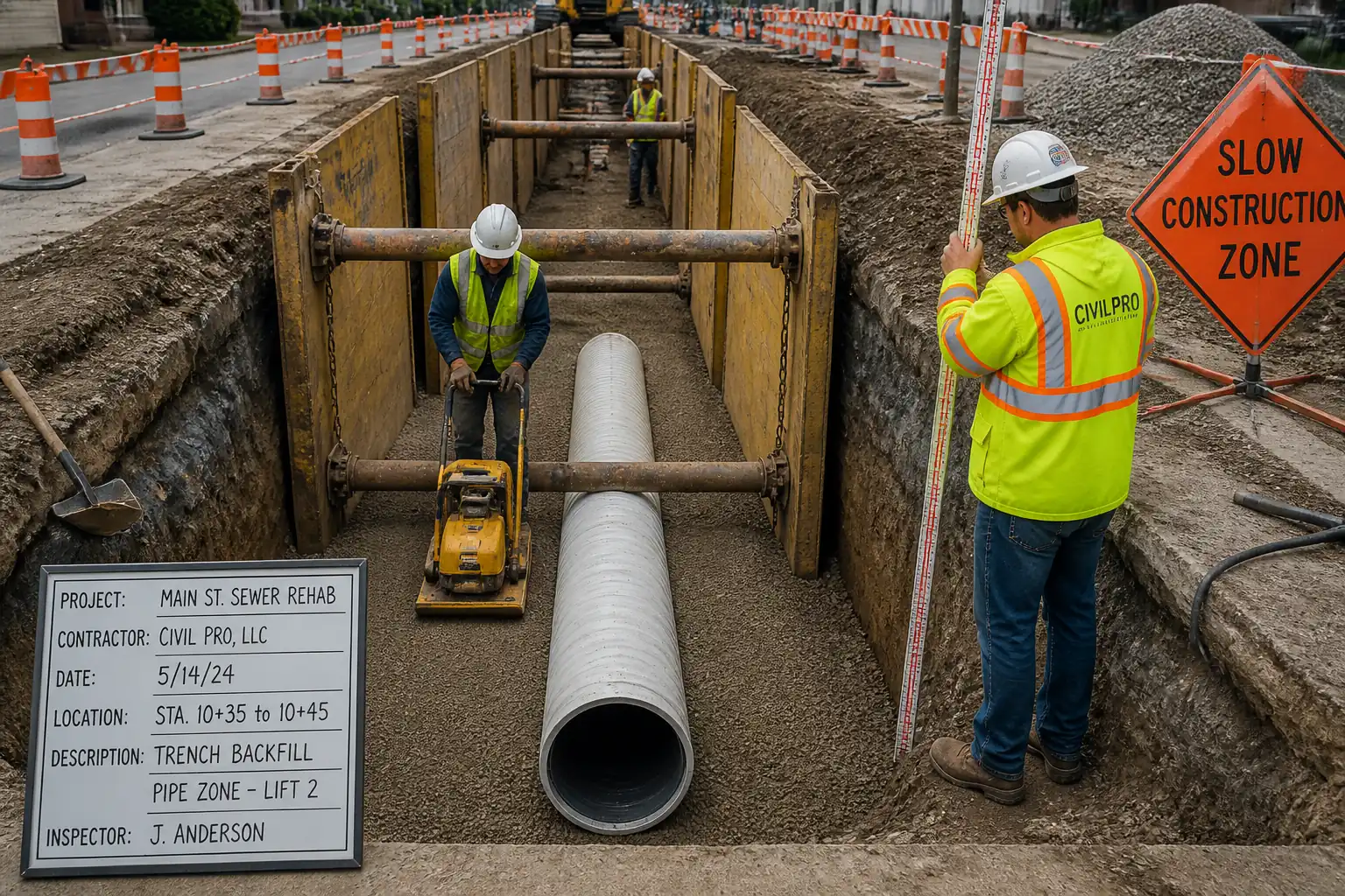
| 3 | Haunching placement | Place granular fill equally on both sides from springline downward/upward in ≤150 mm loose lifts. Rod/tamp under the haunch to lock the pipe without lifting it. Alternate sides to prevent roll. | Foreman/Compaction Operator | Visual; spot level checks |
| 4 | Initial backfill to 300 mm above crown | Continue placing selected granular material in ≤150 mm lifts to at least 300 mm above pipe crown. Compact with low-amplitude plate or light rammer; avoid direct contact with pipe. | Foreman/Compaction Operator | Visual; FDT per ITP |
| 5 | Removal/raising of trench support | Withdraw trench box/shoring in stages not exceeding one lift height behind the backfill level, backfilling immediately to avoid voids against trench sides. | Foreman | Competent Person inspection |
| 6 | General backfill (above pipe zone) | Place approved backfill in 200–300 mm loose lifts. Condition moisture. Compact with appropriate equipment. Keep heavy vibratory rollers ≥1 m from trench edge until backfill level within 0.3 m of surrounding ground. | Foreman/Compaction Operator | Visual; FDT per ITP |
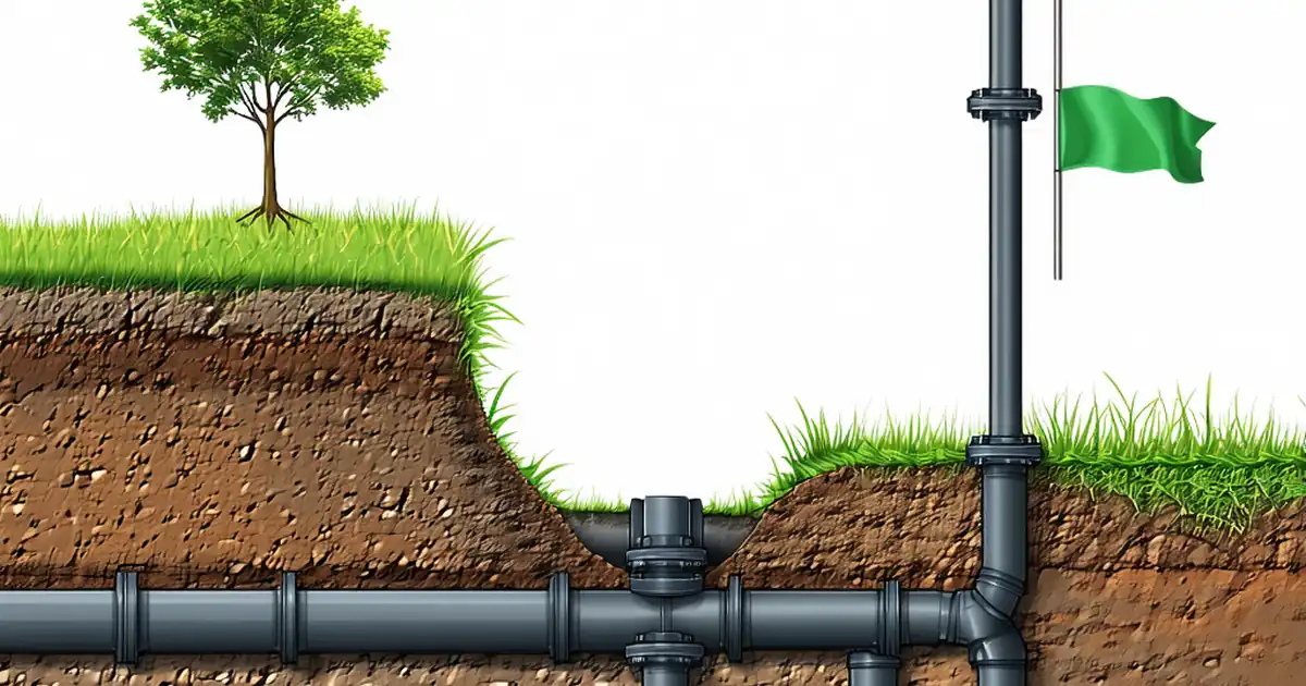
| 7 | Warning tape installation | Install marker tape in the upper backfill at specified depth before final surface restoration. | Foreman | Visual |
| 8 | Surface reinstatement interface | Leave backfill high by 25–50 mm (allowance for settlement) where temporary surfacing is planned. Coordinate with pavement team for base/subbase requirements. | Site Engineer | Level check |
| 9 | Field density testing | Perform FDT at specified frequency by lot and lift. Increase testing if results are borderline or variable materials are encountered. | QA/QC & Third-party Lab | Witness point |
| 10 | Post-backfill monitoring | Schedule deflection test for flexible pipes (mandrel) after stabilization period (e.g., 30 days) and CCTV inspection if specified. | Site Engineer/QAQC | Witness/Review |
Health, Safety and Welfare Controls
Task-specific hazards and controls
- Hazard: Trench collapse during staged backfilling.
- Likely consequence: Fatal crush/asphyxiation.
- Engineering/procedural control: Maintain shoring/trench boxes; only raise/withdraw in small increments not exceeding one lift; daily inspection by a Competent Person; keep spoil ≥0.6 m from edge.
- Required PPE: Hard hat, safety boots, gloves, high-vis, eye protection.
- Collective measures: Edge barriers; ladder access every 7.5–9 m; emergency rescue plan.
-
Inspection/permit: Permit to Excavate; daily excavation inspection log. [Verify per project HSE plan and local regulations]
-
Hazard: Underground utility strike while compacting near live services.
- Consequence: Electrocution, gas leak, service outage.
- Control: Utility plans, CAT & Genny scan, potholing to confirm; mark and protect; set exclusion zones; hand tools within 1 m of confirmed services.
- PPE: Dielectric gloves (as required), eye protection.
- Collective: Briefing maps, tag lines, supervision by Utility Coordinator.
-
Inspection/permit: Permit-to-dig and utility clearance certificates.
-
Hazard: Pipe displacement/damage from compaction energy.
- Consequence: Loss of grade, leaks, future settlement.
- Control: Use low-amplitude plate or hand tamp in pipe zone; ≤150 mm lifts; alternate sides; no vibratory rollers until ≥0.9 m cover; survey spot checks.
- PPE: Gloves, eye/ear protection, boots.
- Collective: Method briefing, equipment selection matrix displayed.
-
Inspection/permit: ITP hold point sign-off before general backfill.
-
Hazard: Plant–people interface and traffic near open trenches.
- Consequence: Struck-by injuries.
- Control: Segregated walkways, banksman, reversible alarms, lighting; TMP with barriers and signage.
- PPE: High-vis, boots, hard hat.
- Collective: Exclusion zones; spotters; speed control.
-
Inspection/permit: Daily TMP inspection; night-work permit if applicable.
-
Hazard: Water ingress and slippery conditions.
- Consequence: Falls, trench instability.
- Control: Active dewatering; sump management; weather monitoring; stop-work for heavy rain; approved discharge route.
- PPE: Waterproof boots, gloves.
- Collective: Access mats; housekeeping.
-
Inspection/permit: Discharge permit; pump inspection log.
-
Hazard: Confined space at tie-ins/manholes.
- Consequence: Asphyxiation, toxic exposure (H2S).
- Control: Avoid entry where possible; if required use confined space permit, gas test, ventilation, harness and retrieval.
- PPE: Gas monitor, harness, respiratory protection if required.
- Collective: Standby attendant; rescue plan.
-
Inspection/permit: Confined Space PTW.
-
Hazard: Noise and vibration from compactors/rollers.
- Consequence: Hearing damage, HAVS.
- Control: Equipment selection with lower vibration; time limits; task rotation; HAVS monitoring.
- PPE: Hearing protection; anti-vibration gloves.
- Collective: Noise barriers near receptors.
-
Inspection/permit: HAVS records; noise monitoring where required.
-
Hazard: Manual handling/awkward postures while tamping.
- Consequence: Musculoskeletal injury.
- Control: Mechanize where possible; use light tools; team lifts; training.
- PPE: Gloves, supportive footwear.
- Collective: Job rotation.
- Inspection/permit: Ergonomic assessment if required.
Environmental Controls
Environmental aspects and controls
- Sediment-laden water from dewatering
- Control: Settle in tank/basin; silt bags; discharge under permit; monitor turbidity as required.
- Dust from handling dry backfill
- Control: Light water spray; cover stockpiles; wheel-wash for road egress; limit drop heights.
- Noise and vibration to nearby receptors
- Control: Work-hour restrictions; maintain equipment; use low-vibe methods; temporary barriers near sensitive locations.
- Waste and spoil management
- Control: Segregate reusable spoil that meets spec; dispose unsuitable material to licensed facility; maintain haulage sheets.
- Hydrocarbon spills from plant
- Control: Drip trays, spill kits, fuel on impervious surface; refuel away from drains; train operators; immediate cleanup and reporting.
- Protection of watercourses and drainage
- Control: Silt fences/wattles; protect inlets; no stockpiles within 10 m of drains where feasible.
- Material selection sustainability
- Control: Prefer reuse of excavated material when it meets gradation/PI and compaction criteria; document approvals.
Quality Assurance and Quality Control
Lotting and testing
- Define lots by uniform material, zone, and length (e.g., 50 m lengths or per manhole-to-manhole). Record lift numbers and dates.
- Minimum testing frequencies (typical – verify per project):
- Pipe zone (bedding/haunch/initial backfill): 1 FDT per 25 m per lift and per pipe size per shift.
- General backfill: 1 FDT per 50 m per lift; at least 1 per 200 m³.
Acceptance criteria (typical – verify per project)
- Pipe zone density: ≥95% of MDD (ASTM D698), moisture within OMC ±2%.
- General backfill in traffic areas or under pavements: ≥98% of MDD (ASTM D1557). Non-traffic areas: ≥95% of MDD (ASTM D698).
- Lift thickness: Pipe zone ≤150 mm; general backfill 200–300 mm depending on equipment and soil type.
- Maximum particle size: ≤19 mm in pipe zone; general backfill ≤ 1/2 of lift thickness (and ≤75 mm typical).
- Survey tolerance before backfill: Invert level ±5 mm; line/grade continuous without sags.
- Deflection for flexible pipes (if tested): ≤5% internal diameter by mandrel/CCTV after stabilization period. [Verify]
Controls to prevent pipe displacement
- Compact alternate sides of pipe; hand tamp under haunch to achieve full side support before loading above crown.
- Use low-amplitude equipment near pipe; prohibit large vibratory rollers until ≥0.9 m cover.
- Keep moisture within specified limits to avoid uplift or loss of support; avoid flooding the trench.
- Maintain temporary restraints or sandbags where specified at curves/steep grades.
Documentation
- Approvals: Material submittals, Proctor curves, method statement, ITP, permits.
- Records: FDT reports with location chainages, moisture content, %MDD, lift number; daily compaction logs; survey reports; plant inspection logs; HSE permits and briefings.
- Nonconformance: Stop work on failing lots, rework (scarify, recondition moisture, recompaction), and retest. Raise NCR and close-out with evidence.
Attachments
Attachments (to be included in the submission)
- Typical trench section details (bedding, haunch, initial backfill, general backfill) and reinstatement layers.
- Equipment selection and compaction matrix by zone and soil type.
- Pre-backfill inspection checklist and daily compaction log template.
- Approved material submittals, Proctor curves, gradation/PI test reports.
- Calibration certificates for density gauges and survey equipment.
- HSE documents: Task risk assessment, Permit to Dig, dewatering/discharge permit, traffic management plan.
- If applicable: Confined Space permit template and rescue plan.
- As-built survey template and lot plan with chainages.
This content is a read-only public reference. Download or customize to get an editable version.
ITP preview
The first inspection activities from the linked ITP for Method Statement: Backfilling and Compaction of Sewer Trenches:
| Activity | Inspection / Test | Acceptance Criteria | Responsibility | Record |
|---|---|---|---|---|
| Material approval and classification | Sieve analysis, PI/LL, organic content as required | Meets gradation, PI, max particle size limits per zone [Verify] | Contractor QA/QC; Client | Material approvals; lab test reports |
| Proctor (MDD/OMC) determination | ASTM D698 (Std) and/or D1557 (Mod) | Valid curve for each material/borrow source | Third-party Lab; QA/QC | Lab reports; curve charts |
| Pre-backfill inspection (Hold) | Survey level/grade; visual of bedding/joints | Invert and alignment within tolerance; bedding continuous | Site Engineer; Client Rep | Checklist; survey report |
Showing 3 of 9 inspection activities. View full ITP →
Related Inspection and Test Plan
An Inspection and Test Plan (ITP) is available for Method Statement: Backfilling and Compaction of Sewer Trenches. The ITP defines the inspection activities, acceptance criteria, hold and witness points, responsible parties, and records required to verify the work described in this method statement.
View the Method Statement: Backfilling and Compaction of Sewer Trenches ITP →Frequently asked questions
Continue with related Quollnet resources connected to this method statement.