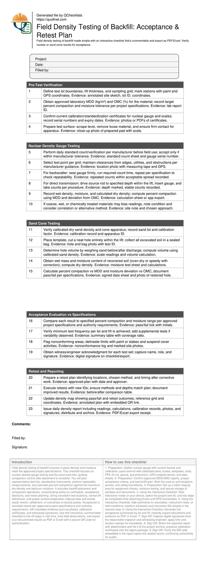
Field Density Testing of Backfill Checklist
Definition: Field density testing of backfill checklist for engineers and inspectors verifying in-place dry density by nuclear gauge or sand cone, documenting acceptance versus specifications and defining retest actions.
- Plan lots, lifts, and grid to sample representatively and efficiently.
- Run nuclear or sand cone correctly with calibrated instruments and records.
- Compare results to project specifications; document pass, fail, and trends.
- Interactive, commentable checklist; export, QR code verification, and sharing.
Field density testing of backfill ensures in-place density and moisture meet the approved project specifications. This checklist focuses on nuclear density gauge testing and the sand cone test, guiding compaction control after placement is complete. You will plan representative test lots, standardize instruments, perform repeatable measurements, and calculate percent compaction against the maximum dry density and optimum moisture. It excludes backfill placement and compaction operations, concentrating solely on verification, acceptance decisions, and retest planning. Using consistent test locations, correct lift references, and proper surface preparation reduces bias and avoids costly rework, settlement, or overstress on buried assets. Acceptance is recorded clearly per approved project specifications and authority requirements, with traceable evidence such as photos, calibration certificates, and witnessed signatures. Use this interactive, commentable checklist to tick off steps in real time, note field observations, and export your documented results as PDF or Excel with a secure QR code for authentication.
- Verify in-place density and moisture with calibrated nuclear gauge or sand cone methods, referenced to approved laboratory maximum dry density and moisture data. Prevent bias by gridding test lots, preparing level test pads, and following manufacturer procedures and project specifications for acceptance.
- Drive confident acceptance decisions by comparing calculated percent compaction and moisture deviation against specified targets, recording evidence such as photos, GPS coordinates, calibration records, and witness signatures. Summarize pass/fail trends by lot and lift to support timely field actions and transparent reporting.
- Interactive online checklist with tick, comment, and export features secured by QR code. Collaborate with site teams, attach readings and calculations, and share daily density reports instantly with stakeholders. Preserve a defensible audit trail that supports approvals, nonconformance tracking, and retention requirements.
Pre-Test Verification
Nuclear Density Gauge Testing
Sand Cone Testing
Acceptance Evaluation vs Specifications
Retest and Reporting
Plan Representative Testing and Establish Traceability
Effective field density testing starts with a sound plan. Define lots by area, lift thickness, and material breaks, then lay out a grid to ensure representative sampling. Confirm the approved laboratory maximum dry density and optimum moisture for the exact backfill used; record report numbers to maintain traceability. Standardize instruments before testing, checking nuclear gauge stability and verifying sand and scale calibrations. Prepare a flat, firm test pad to eliminate seating errors. Maintain adequate edge distances and avoid utilities or obstructions that can distort readings. Capture GPS coordinates and photos for each location to build a defensible record. Establish minimum test frequencies per lot, but add supplemental tests if results vary or moisture control looks inconsistent. This planning reduces retests, ensures coverage, and provides clear evidence for acceptance decisions per approved project specifications and authority requirements.
- Define lots, lifts, and a sampling grid upfront.
- Reference approved MDD/OMC, with report IDs recorded.
- Standardize instruments and verify calibrations daily.
- Prepare level pads and respect edge clearances.
- Capture GPS, photos, and witness details for traceability.
Execute Nuclear Gauge Tests with Consistency
The nuclear density gauge offers rapid in-place density and moisture readings when used consistently. Perform the daily standard count and document serial numbers. Choose backscatter for thin lifts and direct transmission for deeper penetration, aligning the depth with the lift. Seat the gauge firmly on a scraped, flat surface; for direct transmission, drive the source rod cleanly and avoid oversized voids. Run the required count time and repeat per project procedure to assess repeatability. Note conditions that can bias results—coarse, very dry, or chemically treated material—and consider correlation checks or alternative methods if necessary. Record wet density, moisture, and compute dry density and percent compaction relative to the approved MDD, as well as deviation from OMC. Clear, repeatable technique and thorough documentation help demonstrate compliance and quickly isolate nonconforming zones for retest planning.
- Run daily standardization and record stability results.
- Match measurement mode and depth to lift thickness.
- Prepare contact surfaces and avoid edge effects.
- Repeat counts to confirm measurement repeatability.
- Compute percent compaction and moisture deviation.
Sand Cone Method and Acceptance with Retest Strategy
The sand cone test provides a direct volume measurement for density. Use calibrated dry sand and a verified cone; record lot numbers and calibration factors. Excavate a neat hole within the lift using a template and collect all material in a sealed bag. Determine hole volume from sand mass and calibrated density, then measure the wet mass and moisture of the recovered soil (oven-dry or a corrected rapid method). Calculate dry density and percent compaction versus the approved MDD, and compare moisture to the acceptable range. Document pass/fail and test coverage for each lot. For failures, mark limits, communicate a hold, and produce a retest plan after corrective work. Repeat testing with new IDs and map outcomes. Consolidated daily reports with photos, coordinates, calculations, and signatures make acceptance transparent and auditable.
- Use calibrated sand and verified apparatus.
- Collect all excavated soil for moisture testing.
- Calculate hole volume and dry density accurately.
- Compare results to specifications and record pass/fail.
- Plan, execute, and document retests clearly.
How to Use This Interactive Field Density Testing Checklist
- Preparation: Gather nuclear gauge with current license and calibration, sand cone kit with calibrated sand, scales, templates, tools, PPE (hi-vis, gloves, eye protection), GPS-enabled device, and data sheets.
- Preparation: Confirm approved MDD/OMC reports, project acceptance criteria, and test lot/lift plan. Brief the crew on grid locations, access, and safety boundaries.
- Preparation: Set up a clean staging area for equipment checks, moisture testing, and secure storage of samples and documents.
- Using the Interactive Checklist: Start interactive mode on your device, select the project and lot, and tick steps as completed while attaching photos and GPS coordinates.
- Using the Interactive Checklist: Add comments for anomalies, instrument notes, or field conditions; mention witnesses and instrument IDs directly in the relevant step.
- Using the Interactive Checklist: Generate live acceptance summaries by lot and lift; instantly export calculations and evidence as PDF or Excel.
- Sign-Off: Capture digital signatures from the responsible inspector and witnessing engineer; apply time and location stamps for traceability.
- Sign-Off: Share the exported report with stakeholders and file it to the project archive; preserve calibration certificates with the report package.
- Sign-Off: Verify the QR code embedded in the report opens the sealed record, confirming authenticity for audits.
Call to Action
- Start Checklist Tick off tasks, leave comments on items or the whole form, and export your completed report to PDF or Excel—with a built-in QR code for authenticity.
- Download Excel - Field Density Testing of Backfill
- Download PDF - Field Density Testing of Backfill
- View Image - Field Density Testing of Backfill
Cite & Embed
“Field Density Testing of Backfill by Quollnet”
with a link to
this source page.

FAQ
Question: When should I choose nuclear gauge testing versus the sand cone test?
Question: How many field density tests are required per lift or area?
Question: What evidence should be included to support acceptance decisions?
Question: How do I handle failing test results or inconsistent readings?
Related Articles
Broader reading and guidance connected to this checklist topic.


Concrete Cube Test Register Excel Format – Pdf & Excel Sample


Is It Important To Customize Your Qr Code And How To Do It?
Related Checklists
Keep the workflow moving with nearby templates chosen from similar checklist content.