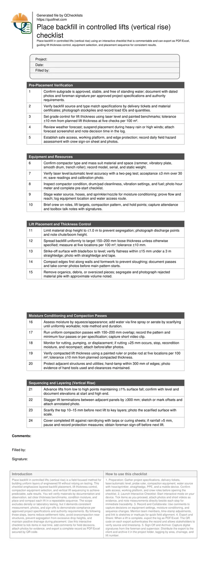
Place backfill in controlled lifts (vertical rise) checklist
Definition: Place backfill in controlled lifts (vertical rise) guides supervisors and inspectors to control lift thickness, equipment selection, and sequencing for safe, uniform placement in layers, explicitly excluding verification by density or laboratory testing.
- Control lift thickness with practical field measurements and visible benchmarks.
- Select and set up compaction equipment matched to material and space.
- Sequence vertical lifts to prevent segregation, sloughing, and trapped water.
- Interactive, commentable checklist; export records with QR code verification.
Place backfill in controlled lifts (vertical rise) is a field-focused method for building uniform layers of engineered fill without relying on testing. This checklist emphasizes layered backfill placement, lift thickness control, compaction equipment selection, and vertical lift sequencing to achieve predictable, safe results. You will verify materials by documentation and observation, set clear thickness benchmarks, condition moisture, and place and compact each lift in a repeatable sequence. The scope excludes density or laboratory testing, but it demands consistent measurement, photos, and sign-offs to demonstrate compliance per approved project specifications and authority requirements. By following these steps, teams reduce settlement risks, avoid overcompaction near structures, prevent segregation from excessive drop heights, and maintain positive drainage during placement. Use this interactive checklist to tick items in real time, add comments for field decisions, attach photos for evidence, and export a complete record as PDF/Excel secured by QR code.
- Ensure uniform backfill by marking target lift thickness, controlling drop heights, and using equipment suited to the material and workspace. Practical measurements, photos, and sign-offs create reliable documentation while reducing settlement, sloughing at edges, and damage to adjacent structures.
- Improve productivity with a consistent vertical rise sequence: prepare subgrade, place thin uniform layers, compact with overlapping passes, protect between lifts, and capture evidence. Crews work faster with fewer reworks, predictable layer geometry, and clear acceptance tolerances noted at each step.
- Interactive online checklist with tick, comment, and export features secured by QR code.
- Record every lift with time-stamped photos, moisture conditioning notes, equipment settings, and measured thickness at defined intervals. This creates transparent traceability for supervisors and clients, supporting compliance with approved project specifications and authority requirements without invoking laboratory testing.
Pre-Placement Verification
Equipment and Resources
Lift Placement and Thickness Control
Moisture Conditioning and Compaction Passes
Sequencing and Layering (Vertical Rise)
Lift thickness control: targets, measurement, and visible benchmarks
Controlling lift thickness is central to predictable backfill performance. Establish your target thickness (often 150–200 mm loose) per approved project specifications and authority requirements, then create visible reference marks using a laser level and spray-painted lines on walls, stakes, or pins. Keep drop heights at or below 1.0 m to avoid segregation, and spread material evenly so the layer is uniform before compaction. Verify thickness with a painted ruler or probe rod at five points per 100 m², logging values and photos. After compaction, remeasure the compacted thickness and confirm it remains within ±10 mm of the planned value. Use a 3 m straightedge to check flatness and document any high spots corrected by strike-off. Capture a short video of the compaction pattern as evidence of uniform coverage. This consistent approach builds confidence in each layer’s geometry without resorting to testing, while providing traceable records for supervisors and clients.
- Set laser benchmarks to guide target lift thickness.
- Measure at five points per 100 m²; log results.
- Maintain drop height ≤1.0 m to limit segregation.
- Check flatness with a 3 m straightedge.
- Photograph measurements with a visible scale.
Equipment selection and vertical sequencing for consistent layers
Match equipment to the space and material: rammers for tight zones, vibratory plates for granular backfill, trench rollers or smooth drum rollers for broader areas. Clean drums and pads to prevent pickup. Define a compaction pattern with 150–200 mm overlaps and complete edge passes first to prevent sloughing. Condition moisture using fine sprays or brief aeration until the material molds without smearing or crumbling. Advance lifts from low to high points, maintaining at least 1% surface fall to shed water and avoid pumping. Stagger lift terminations by at least 300 mm to reduce planes of weakness, and lightly scarify 10–15 mm before the next layer to key lifts together. Hand-tamp within 300 mm of walls, utility lines, and structures to avoid damage from heavier machines. Document model numbers, settings, pass counts, and route maps with photos or short videos for an auditable trail that excludes density or laboratory testing.
- Choose compaction tools to suit material and workspace.
- Overlap passes 150–200 mm; compact edges first.
- Maintain ≥1% fall to control surface water.
- Scarify 10–15 mm before placing the next lift.
- Hand-tamp within 300 mm of sensitive structures.
Documentation, protection between lifts, and practical acceptance cues
Reliable documentation makes each lift defensible and repeatable. Keep time-stamped photos for subgrade, placement, moisture conditioning, and compaction, along with measurement shots showing scales. Record equipment type, settings, pass counts, and any moisture adjustments. Use simple acceptance cues: no visible rutting greater than 25 mm, no pumping underfoot, no segregation bands, and edges stable after compaction. Protect completed lifts with tarps to prevent rain damage or rapid drying; if rainfall exceeds 5 mm, pause work and recondition before continuing. Scarify the top surface 10–15 mm prior to the next lift to ensure a mechanical key. Maintain clean interfaces, free from debris. Secure foreman sign-off before advancing. Export your daily log as PDF/Excel with QR code so stakeholders can verify authenticity and traceability per approved project specifications and authority requirements, without invoking laboratory or field density testing procedures.
- Photograph each stage with scales and landmarks.
- Pause if rutting exceeds 25 mm; recondition material.
- Cover completed lifts against rain and drying.
- Obtain foreman sign-off before advancing.
- Export daily log with QR-secured records.
How to Use This Checklist
- Preparation: Gather project specifications, delivery tickets, laser/automatic level, probe ruler, compaction equipment, water source with hose/sprinkler, straightedge, PPE, and a mobile device. Confirm safe access, working platform, and crew roles before opening the checklist.
- Launch Interactive Checklist: Start interactive mode on your device. Tick items as you proceed, attach photos and short videos as evidence, and note measurements directly beside each step for immediate traceability.
- Record and Collaborate: Use comments to capture decisions on equipment settings, moisture conditioning, and sequence changes. Mention team members, time-stamp adjustments, and link to sketches or markups for quick field alignment.
- Export and Share: When a lift is complete, export the log as PDF/Excel. The QR code on each export authenticates the record and allows stakeholders to verify source and timestamp.
- Sign-Off and Archive: Capture digital signatures from the foreman and supervisor. Distribute the export to the client and archive it in the project folder, tagging by area, chainage, and lift number.
Call to Action
- Start Checklist Tick off tasks, leave comments on items or the whole form, and export your completed report to PDF or Excel—with a built-in QR code for authenticity.
- Download Excel - Backfill Placement in Controlled Lifts (Vertical Rise)
- Download PDF - Backfill Placement in Controlled Lifts (Vertical Rise)
- View Image - Backfill Placement in Controlled Lifts (Vertical Rise)
Cite & Embed
“Backfill Placement in Controlled Lifts (Vertical Rise) by Quollnet”
with a link to
this source page.

FAQ
Question: What is a practical lift thickness for most backfill operations?
Question: Which compaction equipment should I use in tight areas versus open areas?
Question: How do I manage wet or dry backfill without lab testing?
Question: When should I pause placement due to weather or surface condition?
Question: How do I avoid damage around utilities and structures while compacting?
Related Articles
Broader reading and guidance connected to this checklist topic.


Safety In Construction: The Role Of Periodic Safety Checklists

Related Checklists
Keep the workflow moving with nearby templates chosen from similar checklist content.