Place Blinding Concrete (Horizontal) Checklist
Definition: Place Blinding Concrete (Horizontal) checklist for site engineers verifies thickness, closed finish, curing, and reinforcement readiness on slabs and footings, excluding any waterproofing activities or materials.
- Control thickness and level with lasers, depth pins, and surveys.
- Achieve a dense, smooth finish that prevents laitance and debris.
- Cure promptly to protect against cracking and surface dusting.
- Interactive, commentable, export-ready checklist with QR code verification.
Place Blinding Concrete (Horizontal) establishes a uniform, durable working surface that ensures reliable thickness, a clean closed finish, proper curing, and verified readiness for reinforcement. Often called lean concrete blinding or a mud slab, this horizontal blinding layer provides a stable, level base that minimizes contamination, protects the subgrade, and supports precise rebar placement. This checklist focuses strictly on horizontal blinding concrete beneath structural elements and explicitly excludes waterproofing. By controlling level and thickness, you reduce high spots that lift reinforcement, prevent soft areas that cause rebar chair punch-in, and avoid laitance that can impair bond. Proper curing reduces dusting and early-age cracking while keeping the surface sound for subsequent fixing operations. Each step includes acceptance cues, tolerances, and evidence requirements so you can prove compliance per approved project specifications and authority requirements. Use this interactive checklist to tick tasks, add comments, attach photos and readings, and export to PDF/Excel with a secure QR for traceable sign-off.
- Authenticate blinding quality with clear, field-ready steps covering thickness control, surface finish, curing, and reinforcement readiness. Each task specifies tools, tolerances, and evidence, enabling consistent inspections across bays and pours while avoiding ambiguity and scope creep into waterproofing or vertical elements.
- Reduce rework and delays by measuring thickness at a defined grid, achieving a closed, flat finish, and documenting curing start–finish times. Photos, batch tickets, and level logs provide hard proof that the blinding layer supports accurate rebar placement and avoids laitance, dusting, or chair indentation.
- Interactive online checklist with tick, comment, and export features secured by QR code. Inspectors capture readings, upload geotagged photos, and request approvals in real time, creating a robust audit trail that is easy to review, share, and archive for quality assurance and handover.
- Deliver predictable outcomes by aligning site methods with approved project specifications and authority requirements. Laser levels, 2 m straightedges, depth pins, and calibrated thermometers guide practical acceptance decisions, while hold-point releases ensure reinforcement proceeds only when blinding is demonstrably ready.
Pre-Placement Checks
Placement and Thickness Control
Surface Finish and Edges
Curing and Protection
Readiness for Reinforcement
Documentation and Sign-Off
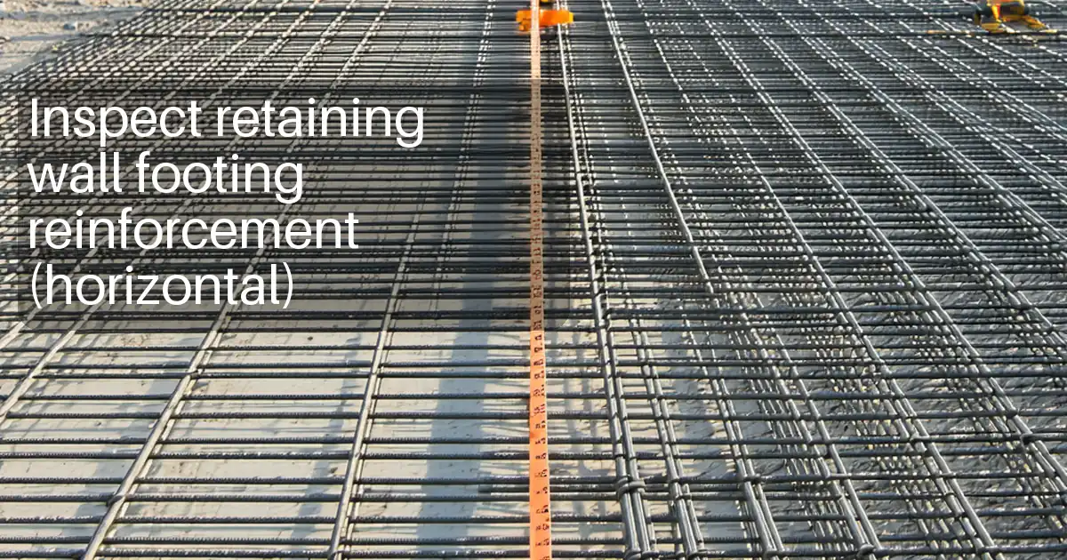
Controlling Thickness and Levels
Uniform blinding thickness underpins reliable reinforcement support. Establish a control system using screed rails, laser levels, and depth pins set to the design top of blinding. During placement, strike-off to the pins and verify level with a 2 m straightedge. Record spot levels on a practical grid—typically 5 m—plus additional checks around edges and penetrations where thin spots often occur. Keep pour sequences continuous to avoid cold joints, and log pauses if they are unavoidable. Validate slump, temperature, and delivery times to ensure consistent workability and finishing windows. After strike-off, probe thickness at representative points to confirm no area falls below the specified minimum. Document every reading, tie it to a benchmark, and photograph pin layouts and checks. These steps provide defensible evidence that the blinding will not compromise chair bearing or reinforcement cover control, aligning with approved project specifications and authority requirements.
- Use lasers and depth pins referenced to a fixed benchmark.
- Check flatness with a 2 m straightedge in two directions.
- Probe edges and penetrations for minimum thickness compliance.
- Log slump, temperature, delivery times, and pour sequence.
Achieving a Closed, Durable Finish
A closed, dense finish minimizes laitance and dusting, creating a clean base for reinforcement. Time finishing to occur after bleed water has dissipated, then steel-float to close pores without overworking the surface. Verify flatness routinely with a 2 m straightedge and correct minor highs immediately. Form crisp, straight edges and address small voids while the concrete remains workable. After finishing, ensure there is no standing water or debris that could contaminate reinforcement. Photograph representative textures and edges for the record. Acceptance relies on uniform appearance, absence of ridges and tears, and straight arises without honeycombing. These cues provide practical assurance that rebar chairs will seat firmly and that subsequent marking for gridlines will be legible and durable, all while adhering to the approved project specifications and authority requirements.
- Finish after bleed water dissipates to avoid laitance.
- Steel-float to close the surface and densify paste.
- Maintain straight, defect-free edges and arises.
- Remove standing water and loose debris promptly.
Curing and Reinforcement Readiness
Prompt, continuous curing preserves surface strength and reduces early-age cracking. Choose a method—wet coverings, polythene, or curing compound—per approved project specifications and authority requirements, and start as soon as finishing allows. Maintain curing continuity for the specified duration, verifying moisture or membrane integrity daily. Protect the surface from traffic, contamination, and rain until inspection confirms integrity. After curing, remove coverings and confirm the surface is clean, dry to touch, and dust-free. Conduct chair seating checks; chairs should not rock or indent noticeably. Transfer survey control lines, verify spot levels, and confirm embedded supports are secure. Only then seek QA/consultant release to commence steel fixing. This sequence ensures the blinding genuinely supports reinforcement placement without rework, delays, or hidden defects.
- Begin curing promptly and maintain it continuously.
- Log method, times, and product lot numbers.
- Prevent traffic and contamination until inspection.
- Confirm chair seating and survey control before release.
How to Use This Blinding Concrete Checklist
- Preparation: Brief the team on scope (horizontal blinding only). Gather laser level, depth pins, 2 m straightedge, slump cone, thermometers, curing materials, and PPE. Open approved drawings and specifications.
- Set up devices: Ensure the checklist app is online, camera and location services enabled, and calibration certificates for instruments are available for upload.
- Start interactive mode: Create a new entry per pour/bay, set location and date, add responsible inspector, and list any hold points to be cleared.
- During works: Tick items as completed, attach photos/readings, and use comments to resolve issues with contractors in real time.
- Curing and readiness: Log curing start–finish times, protection measures, and readiness checks. Request QA review within the app.
- Export: Generate a QR-authenticated PDF/Excel report with photos, readings, and signatures. Share with stakeholders for review.
- Sign-off: Capture digital signatures from contractor, inspector, and consultant. Archive the record in the project EDMS for traceability.

Call to Action
- Start Checklist Tick off tasks, leave comments on items or the whole form, and export your completed report to PDF or Excel—with a built-in QR code for authenticity.
- Download Excel - Place Blinding Concrete (Horizontal)
- Download PDF - Place Blinding Concrete (Horizontal)
- View Image - Place Blinding Concrete (Horizontal)
Cite & Embed
“Place Blinding Concrete (Horizontal) by Quollnet”
with a link to
this source page.
FAQ
Question: What thickness should blinding concrete be, and how do I verify it?
Question: How long should I cure blinding before placing reinforcement?
Question: What finish is acceptable for blinding concrete under reinforcement?
Question: How can I measure and document level across large bays efficiently?
Related Articles
Broader reading and guidance connected to this checklist topic.


Related Checklists
Keep the workflow moving with nearby templates chosen from similar checklist content.