
Method Statement – Laying of Reinforced Concrete (RC) Sewer Pipes with Crane Lifting, Bedding, Rubber Gasket Jointing, Alignment Control, Concrete Surround/Cradle, and Joint Gap Inspection – Method Statement
AI-assisted method statement with matching ITP, PDF download, and Excel export.
More than a static template
Unlike a downloadable Word or PDF template, this method statement is an AI-assisted editable starting point connected directly to a matching Inspection and Test Plan. Every section is structured, project-adaptable, and ready to export.
- AI-assisted drafting — Customize every section with AI for your specific project scope.
- Linked ITP — A matching inspection and test plan is generated alongside the method statement.
- Multiple export formats — Download as a formatted PDF or editable Excel spreadsheet.
- Editable starting point, not a final document — Review, verify, and adjust all content against your project requirements before use.
Static template vs. Quollnet workflow
| Feature | Static template | Quollnet |
|---|---|---|
| Project-specific content | Manual fill-in required | AI-assisted customization |
| Linked ITP | Separate document, no link | Matching ITP included |
| Export formats | Usually PDF only | PDF and Excel |
| Structured sections | Free-form layout | 13 standardized sections |
| Saved to your account | Local file only | Cloud-saved, reusable |
| Content accuracy | You verify everything | AI-assisted, you still verify |
| Cost | Often free but time-intensive | Free to customize and download |
What you can customize
When you save this method statement to your account, every section becomes editable. The following 13 sections are included:
- Scope — Defines the activity and its boundaries.
- References — Standards, specifications, and drawings.
- Responsibilities — Roles and accountabilities.
- Resources — Labour, plant, and equipment summary.
- Materials — Materials and compliance requirements.
- Equipment — Tools and equipment details.
- Prerequisites — Hold points and pre-conditions.
- Method sequence — Step-by-step construction sequence.
- Safety controls — HSE risk controls and PPE.
- Environmental controls — Environmental mitigation measures.
- QA/QC — Quality inspection and test requirements.
- ITP — Inspection and Test Plan table (has its own page).
- Attachments — Referenced drawings and documentation.
Why this method statement is used
This method statement is used to define and communicate the approved procedure for carrying out method statement – laying of reinforced concrete (rc) sewer pipes with crane lifting, bedding, rubber gasket jointing, alignment control, concrete surround/cradle, and joint gap inspection on site. It ensures the work is planned in advance, the correct resources and controls are in place, and all personnel understand responsibilities, sequence, quality requirements, and safety controls before work begins. It aligns site execution with the documented scope and acceptance expectations.
Who uses this method statement
This method statement is used by contractors, site supervisors, project engineers, QA/QC engineers, HSE officers, consultants, and client representatives. It serves as a shared reference for planning, execution, supervision, inspection, and approval of the activity on site.
When it is prepared and submitted
The method statement is prepared before the work activity starts and submitted as part of the pre-construction documentation package for review and approval.
Who reviews or approves it
The method statement is usually submitted to the client representative, consultant, resident engineer, or project management consultant for review and approval before the work commences.
Important approval note
This method statement is an AI-assisted editable starting point, not a pre-approved document. Before use on any project, all content must be reviewed and approved by the relevant parties (superintendent, principal contractor, or client representative) in accordance with your contract and project quality plan.
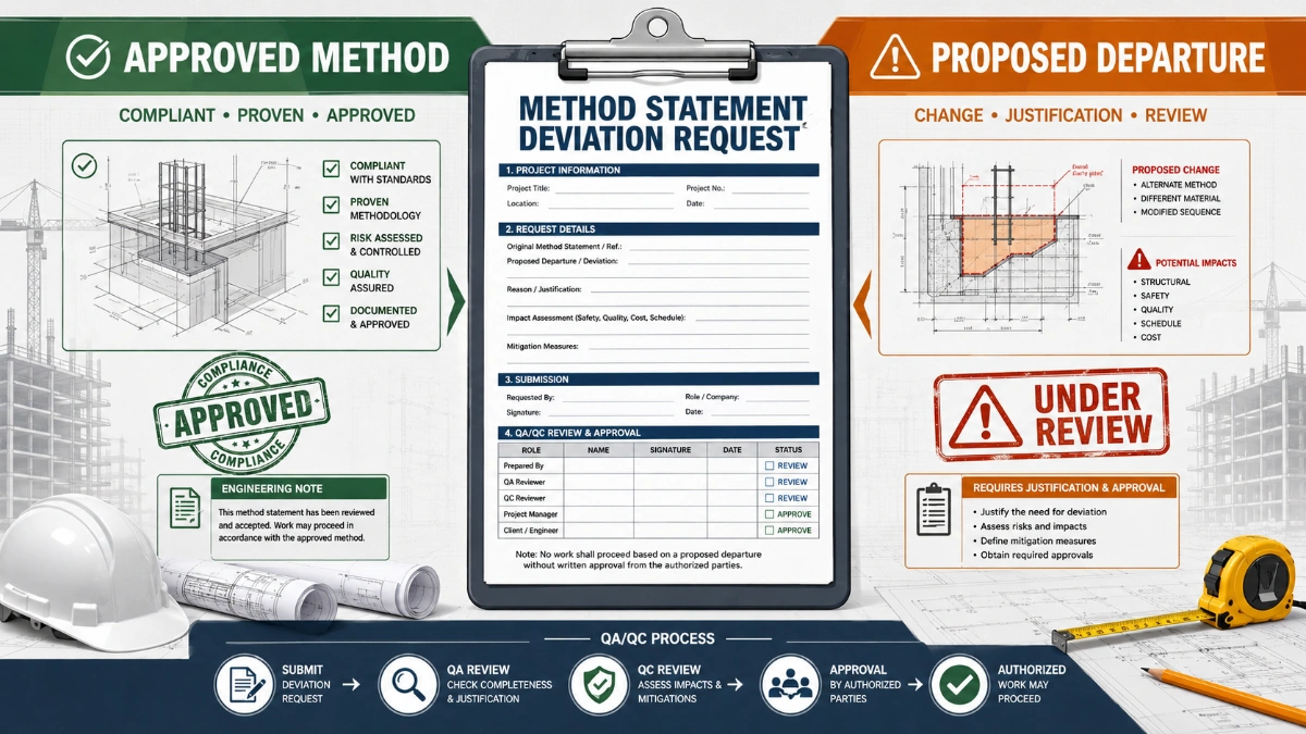
For example: if your specification requires a departure from a referenced standard, that departure must be documented and approved separately — this method statement will not capture that automatically. Always verify against your applicable drawings, specifications, and regulatory requirements.
Method statement content
Scope
Overview
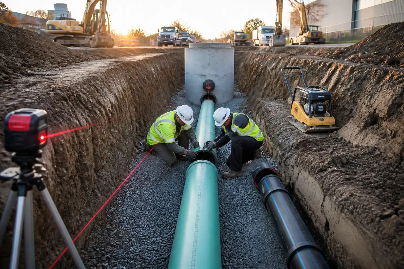
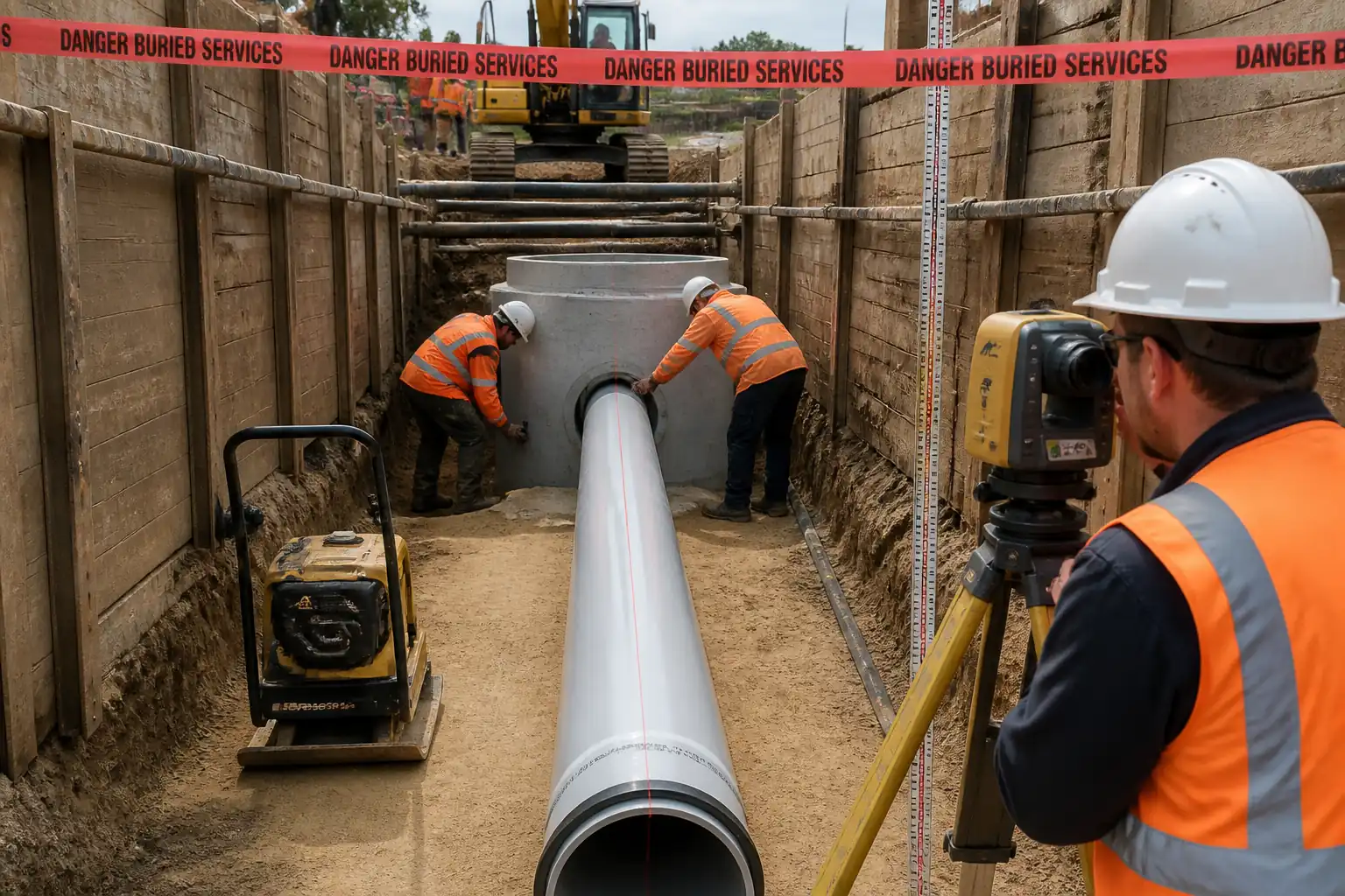
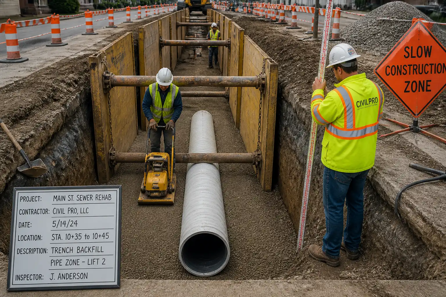
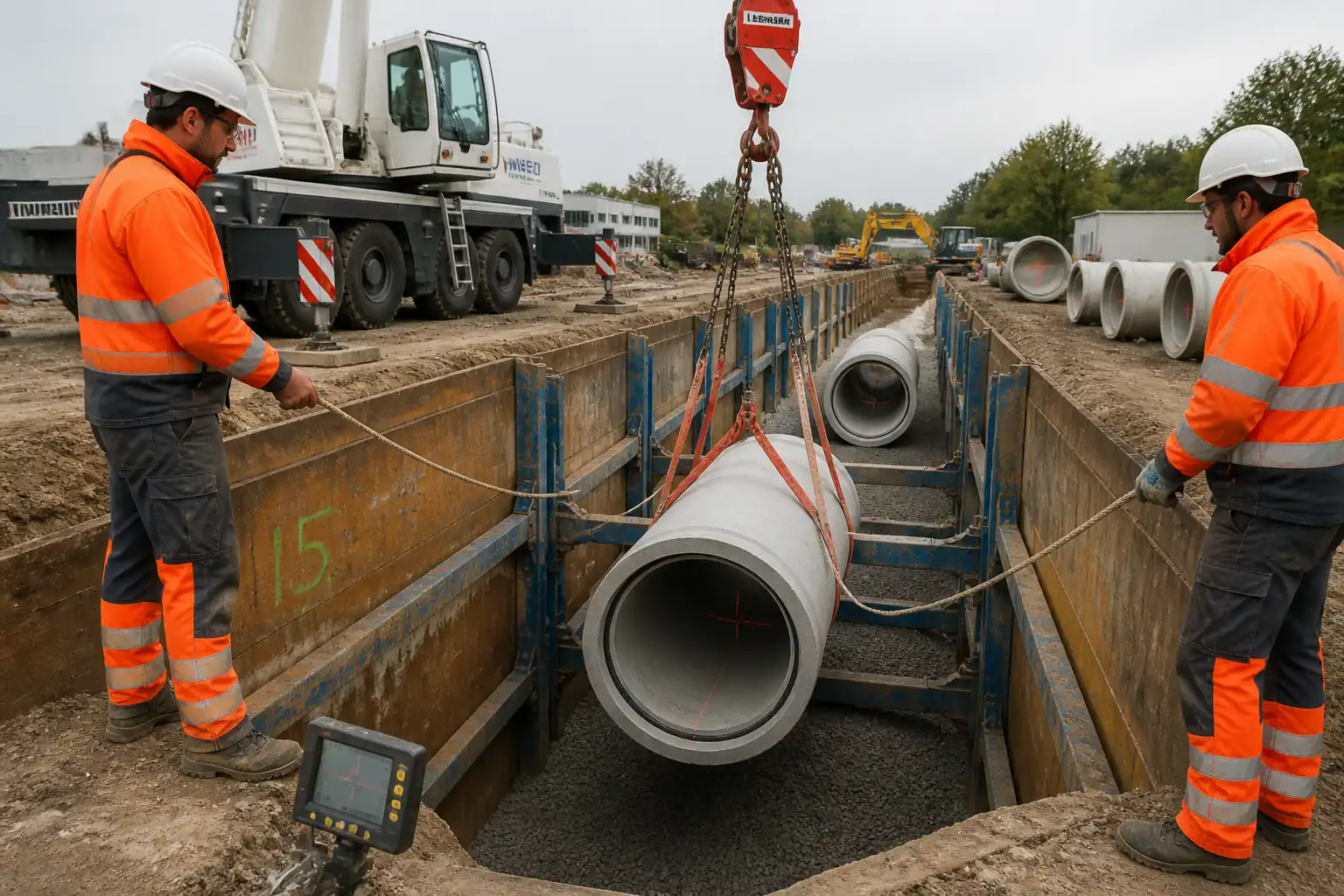
This method statement covers the end-to-end installation of reinforced concrete (RC) gravity sewer pipelines, including: trenching and temporary works, trench bed preparation, granular bedding/haunching, crane lifting and placement of RC pipes, jointing using elastomeric rubber gaskets, alignment and level control using a pipe laser, installation of concrete surround or cradle where required, joint gap inspections prior to backfilling, controlled backfilling and compaction, leakage testing (air or water), CCTV inspection (if specified), reinstatement, and documentation for handover.
Inclusions
- Excavation of pipe trenches and provision of temporary works/shoring where required.
- Dewatering, if needed, to maintain dry and stable formation.
- Trench formation trimming and granular bedding installation.
- Delivery, handling, and storage of RC pipes and elastomeric gaskets.
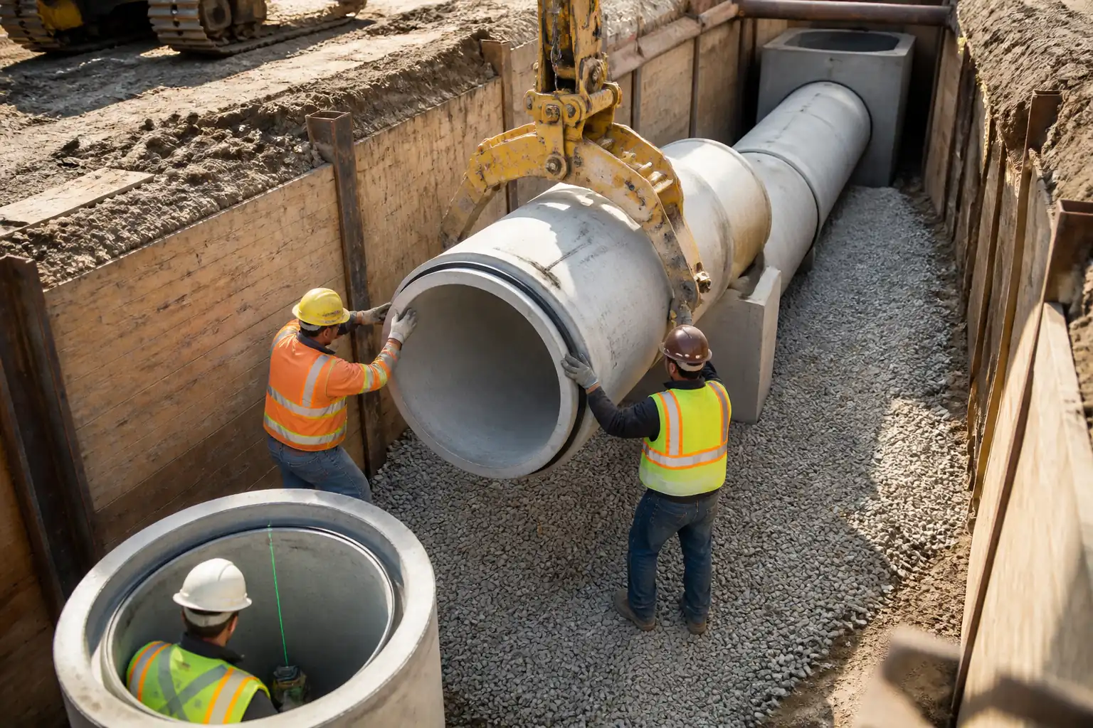
- Lifting operations using a mobile crane and certified lifting accessories.
- Pipe laying, jointing, alignment/level checks, and witness marking.
- Placement of concrete surround/cradle where specified on drawings.
- Initial sidefill/haunching and initial backfill to above pipe crown.
- Testing: air or water leakage tests per standards; CCTV (if specified).
- Final backfilling and surface reinstatement.
- As-built survey and QA/QC record collation.
Exclusions
- Manhole construction beyond pipe connection stubs (unless specified).
- Permanent diversion of existing services.
- Long-term dewatering systems.
- Road surfacing beyond reinstatement limits shown on drawings.
Key Constraints/Assumptions
- Gravity sewer installation on prepared formation using granular bedding unless concrete cradle/surround is detailed.
- Pipe sizes, classes, and line/level tolerances to be verified against project specifications and drawings. [Verify per project specifications]
- Lifting plans and temporary works designs to be approved prior to works. [Verify per project HSE plan and local regulations]
References
| Document Type | Reference / Number | Revision | Notes |
|---|---|---|---|
| Standard | EN 1610 | ||
| Standard | EN 1916 / BS 5911-1 | ||
| Standard | EN 681-1 | ||
| Standard | BS 6031 | ||
| Standard | BS 5975 | ||
| Standard | BS 7121 | Equivalent local regulations (e.g., LOLER/PUWER, ASME B30.5) may apply [Verify] | |
| Standard | ASTM C76/C76M | Use where project specifies ASTM-based products | |
| Standard | ACI 301 / ACI 318 / ACI 117 | Use as reference where concrete surround/cradle is required | |
| Standard | ISO 9001 / ISO 14001 / ISO 45001 |
Responsibilities
| Role | Responsibility | Name / Party |
|---|---|---|
| PM | Management | Contractor |
| Engineer | Engineering | Contractor |
| AP | Lifting operations | Contractor |
| Operator | Operations | Subcontractor/Contractor |
| Banksman | Lifting control | Contractor |
| TWC | Temporary works | Contractor |
| QA/QC | Quality control | Contractor |
| HSE | HSE | Contractor |
| Surveyor | Survey | Contractor |
| Engineer | Client oversight | Engineer/Client |
Resources (Manpower)
| Resource Type | Description | Quantity | Remarks |
|---|---|---|---|
| Manpower | Directs crew on site | 1 | |
| Manpower | Pipe placement, jointing, bedding/haunching | 3–6 [Verify] | |
| Manpower | Trench excavation and trimming | 1–2 | |
| Manpower | Lifting and placing pipes/accessories | 1 + 2 | |
| Manpower | Sidefill, backfill compaction in layers | 2–4 | |
| Manpower | Concrete surround/cradle placement and finishing | 2–3 |
Materials
| Material | Specification / Grade | Quantity | Remarks |
|---|---|---|---|
| RC Pipe | EN 1916 / BS 5911-1 or ASTM C76 | As per BOQ | |
| Rubber gasket | EN 681-1 | 1 set/joint + spare 2% | |
| Granular bedding | EN 1610 guidance / Project spec [Verify] | As required | |
| Concrete | EN 206 / ACI 301 [Verify] | As per drawings | |
| Lubricant | Manufacturer data | As required | |
| Geotextile | EN 13249/13250 [Verify] | As required | |
| Testing kit | EN 1610 methods | Set per test section |
Equipment
| Equipment | Capacity / Type | Quantity | Inspection Required |
|---|---|---|---|
| Crane | 25–80 t [Verify] | 1 | Yes |
| Tracked/wheeled | 20–30 t [Verify] | 1–2 | Yes |
| Shoring system | As required | Yes | |
| Various | Set | Yes | |
| Laser | 1 | Yes | |
| Survey instrument | 1 | Yes | |
| Rigging gear | Per plan | Set | Yes |
| Pumps | e.g., 20–50 m³/h [Verify] | As needed | Yes |
| Multi-gas meter | 1 | Yes |
Prerequisites & Preparations
Approvals & Documentation
- Approved IFC drawings, this Method Statement, and ITP.
- Lift plan approved by Appointed Person and Engineer. [Verify per project HSE plan and local regulations]
- Temporary Works Design (TWD) for trench shoring and crane mats/ground bearing verification approved by TWC/Engineer.
- Material approvals: RC pipes, gaskets, bedding aggregate, concrete mix design, lubricant.
- Calibrations in date: pipe laser, levels, pressure gauges, gas detectors.
Permits & Surveys
- Permit-to-Dig with utility search and mark-up; trial pits to confirm depths/locations of utilities.
- Permit-to-Lift with exclusion zone plan and traffic management (if adjacent to live carriageways).
- Dewatering/discharge permit and sediment control plan (if needed).
- Confined space permit where entry into manholes/shafts is required. [Verify]
Site Readiness
- Access roads/platforms prepared; crane pads/mats installed per TWD.
- Trench alignment set out; reference benchmarks and control points established.
- Materials delivered, inspected, and stored on firm level ground with pipe supports/chocks; gaskets stored clean and shaded.
- Pre-start briefings/toolbox talks covering utility risks, lifting, excavations, and testing procedures.
- Emergency plan, rescue equipment (tripod/winch) if entering confined spaces, spill kits, and first-aid arrangements.
Method Sequence
| Step | Activity | Description | Responsibility | Inspection / Hold Point |
|---|---|---|---|---|
| 1 | Pre-start & Setting Out | Confirm permits, approvals, and survey control. Establish pipe alignment/levels; set laser grade from downstream control (invert). | Site Engineer / Surveyor | Document check |
| 2 | Utility Clearance & Trial Pits | Mark services; hand-dig/vacuum potholing to prove positions and depths. | Foreman / HSE | Hold point (Engineer) |
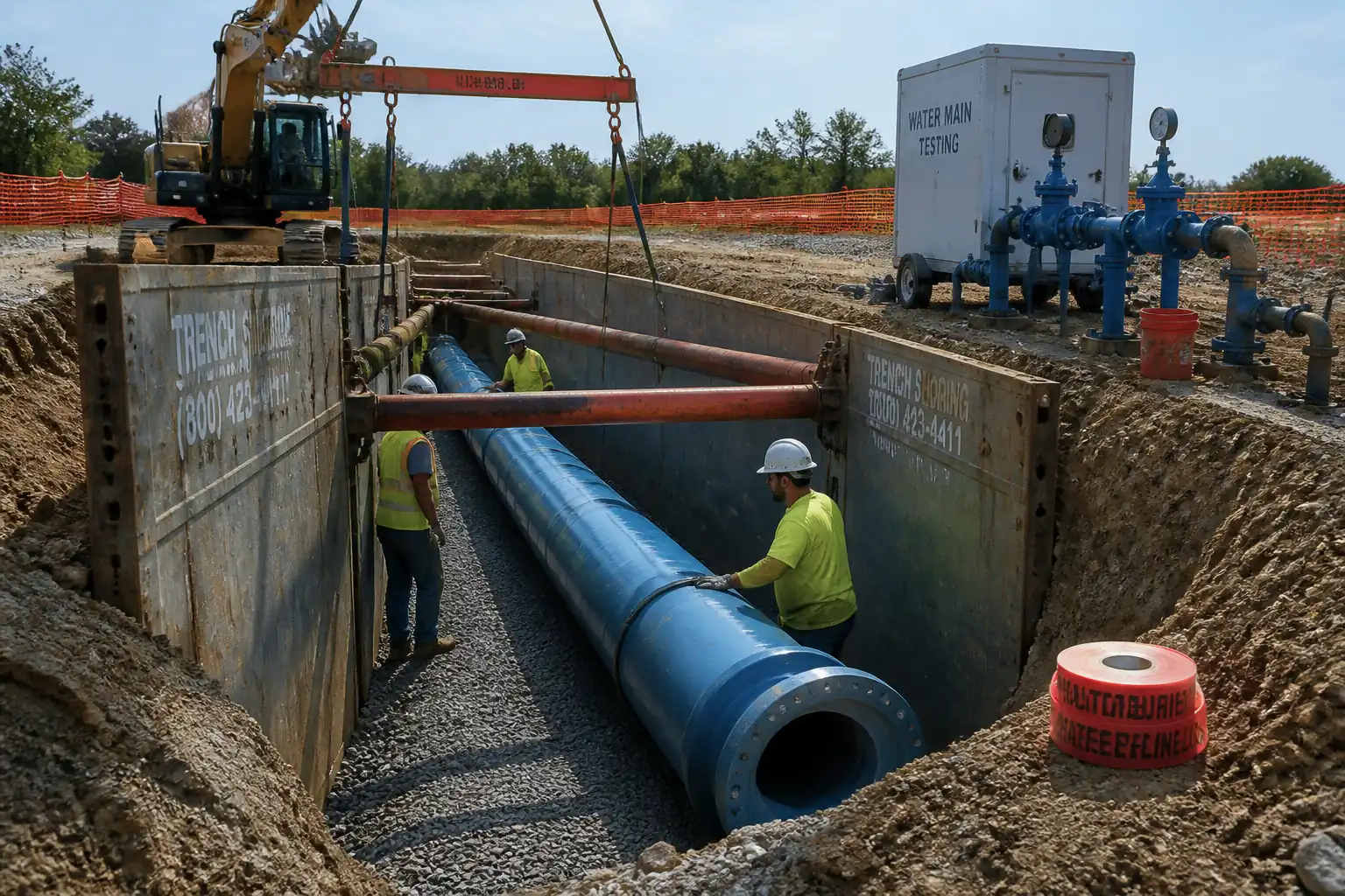
| 3 | Temporary Works Install (Shoring/Boxes) | Install trench support per TWD as excavation progresses. Inspect daily and after events (rain/impact). | TWC / Foreman | Hold/Witness |
| 4 | Excavation to Formation | Excavate trench to design depth allowing for bedding thickness. Control overbreak; maintain safe batters/exclusion zones. | Excavator Operator / Foreman | Surveillance |
| 5 | Formation Preparation | Trim formation; proof-roll if feasible; install geotextile where specified; correct any pumping/soft areas. | Foreman / Site Engineer | Witness |
| 6 | Bedding Placement & Compaction | Place granular bedding (typ. 100–150 mm) and level to grade; compact in layers (≤150 mm). Set laser on target blocks. | Foreman / Compaction Crew | Hold (Engineer) before pipe lay |
| 7 | Material Receipt & Inspection | Inspect RC pipes/gaskets on delivery and prior to install; clean spigots/sockets; apply lubricant to gasket/spigot per manufacturer. | QA/QC Engineer / Foreman | Witness |
| 8 | Crane Setup & Pre-Lift | Set crane on prepared pads/mats; verify outriggers fully deployed; rig per plan with spreader/web slings; attach tag lines. | AP / Crane Operator / Banksman | Hold (AP) |
| 9 | Lower and Bed First Pipe | Lift pipe using rated lifting points or slings; lower to trench; set on bedding with laser target aligned; prevent damage to socket/gasket. | Banksman / Pipe Layers | Surveillance |
| 10 | Jointing with Rubber Gasket | Fit gasket to spigot (or socket) as per manufacturer; lubricate; align and push home using crane/come-along. Mark insertion witness line. | Foreman / Pipe Layers | Witness (QA/QC) |
| 11 | Joint Gap & Angular Deflection Check | Measure external joint gap or confirm insertion mark; check allowable angular deflection per DN/manufacturer; paint witness marks across joint. | QA/QC Engineer | Hold (Engineer) |
| 12 | Haunching and Sidefill | Place and compact granular material equally on both sides to springline and haunch to 30–50% of diameter height. | Compaction Crew | Witness |
| 13 | Concrete Surround/Cradle (If Required) | Install spacer blocks; place concrete under and around pipe per detail; avoid floatation; vibrate lightly; cure. | Concrete Crew | Hold (QA/QC + Engineer) pre/post pour |
| 14 | Initial Backfill to Above Crown | Place selected granular material to min. 300 mm above crown; compact in ≤150 mm layers. | Compaction Crew | Witness |
| 15 | Leakage Testing (Air or Water) | Isolate test section between manholes/stoppers; perform low-pressure air or hydrostatic water test as per EN 1610. | QA/QC Engineer | Hold (Engineer) |
| 16 | CCTV Inspection (If Specified) | Survey pipeline for defects, displacement, infiltration, or debris. | Specialist Subcontractor | Witness |
| 17 | Final Backfill & Reinstatement | Complete backfill per specification; compact in layers; reinstate surfaces to match existing/requirements. | Foreman / Compaction Crew | Surveillance |
| 18 | As-Built Survey & Handover Records | Survey inverts, chainage, alignment; compile QA dossier (ITP, tests, material certs, approvals). | Surveyor / QA/QC | Final inspection |
Health, Safety and Welfare Controls
Key Task-Specific Hazards and Controls
- Hazard: Underground utility strike (gas/electric/telecom)
- Likely consequence: Electrocution, explosion, service outage.
- Engineering/procedural control: Permit-to-Dig; utility plans; CAT & Genny scan; vacuum or hand-dig trial pits; maintain exclusion distances; live service supports if exposed.
- Required PPE: Class 00 insulated gloves for electrical checks [Verify], arc-rated PPE if required; safety boots; eye protection.
- Collective measure: Physical barriers and signage around exposed services.
-
Inspection/permit/supervision: Supervisor sign-off of trial pits; HSE Officer to verify PTD; Engineer witness at hold point.
-
Hazard: Trench collapse/ingress of soil
- Likely consequence: Burial, crush injuries, fatalities.
- Engineering/procedural control: Shoring/boxes or battering per TWD; daily inspection; access/egress ladders every 6–9 m; keep surcharge >1 m from edge; water control.
- Required PPE: Helmet with chin strap; steel-toe boots; gloves.
- Collective measure: Edge protection (guardrails/toe boards); trench access control.
-
Inspection/permit/supervision: TWC inspections daily/after rainfall; excavation permit.
-
Hazard: Crane operations and suspended loads
- Likely consequence: Struck-by, crushing, overturning.
- Engineering/procedural control: BS 7121 lift plan; certified crane and rigging; ground bearing verified; tag lines; exclusion zone; weather/wind limits per OEM.
- Required PPE: High-vis; helmet with chin strap; gloves; safety boots.
- Collective measure: Marshalled exclusion zone with barriers; banksman control.
-
Inspection/permit/supervision: Appointed Person approval; pre-lift checklist; lift permit.
-
Hazard: Pinch points during jointing and pipe alignment
- Likely consequence: Hand injuries, fractures.
- Engineering/procedural control: Use come-alongs/jacks; keep hands off crush points; use alignment bars with handles; brief crew on hand positions.
- Required PPE: Impact-resistant gloves.
- Collective measure: Clear communication and stop signals; banksman oversight.
-
Inspection/permit/supervision: Supervisor to enforce safe system; toolbox talk record.
-
Hazard: Confined space and toxic gases (H2S, CH4, low O2)
- Likely consequence: Asphyxiation, poisoning, explosion.
- Engineering/procedural control: No entry unless permitted; gas test before entry; forced ventilation; standby/rescue plan with tripod/winch.
- Required PPE: Gas monitor; harness; escape set as required [Verify].
- Collective measure: Barricade entries; confined space signage.
-
Inspection/permit/supervision: Confined Space Permit; competent attendant.
-
Hazard: Contact with wet concrete (surround/cradle)
- Likely consequence: Chemical burns, dermatitis.
- Engineering/procedural control: Controlled pouring; washing facilities; prohibit bare-skin contact; use long tools to place/vibrate lightly.
- Required PPE: Alkaline-resistant gloves; long sleeves; goggles.
- Collective measure: Designated washout and eyewash station.
-
Inspection/permit/supervision: Supervisor to check PPE; HSE audits.
-
Hazard: Slip/trip in trench and uneven surfaces
- Likely consequence: Sprains/fractures.
- Engineering/procedural control: Good housekeeping; illuminate trench; maintain access boards/walkways.
- Required PPE: Anti-slip boots; headlamp where needed.
- Collective measure: Temporary lighting; edge protection.
-
Inspection/permit/supervision: Daily housekeeping checks.
-
Hazard: Noise, vibration, and dust from excavation/compaction
- Likely consequence: Hearing loss, HAVS, respiratory irritation.
- Engineering/procedural control: Maintain equipment; water mist for dust; limit exposure time; rotate tasks; use low-vibration tools.
- Required PPE: Hearing protection; FFP2/FFP3 masks as needed.
- Collective measure: Acoustic barriers where practical.
-
Inspection/permit/supervision: Noise/vibration monitoring if required; HSE plan compliance. [Verify]
-
Hazard: Working near traffic or public
- Likely consequence: Vehicle strike.
- Engineering/procedural control: Traffic management plan; barriers; signage; spotters.
- Required PPE: High-vis class per road category.
- Collective measure: Temporary traffic control devices.
-
Inspection/permit/supervision: Road work permit; daily checks.
-
Hazard: Laser exposure from pipe laser
- Likely consequence: Eye injury.
- Engineering/procedural control: Use Class 2/3R devices only; avoid direct eye exposure; cap beam when not in use.
- Required PPE: None typically; follow OEM instructions.
- Collective measure: Inform crew; signage if necessary.
- Inspection/permit/supervision: Equipment induction; calibration/label check.
[All local legal requirements and project HSE plan controls to be verified]
Environmental Controls
Key Environmental Aspects and Controls
- Dewatering and Discharge
- Risk: Turbid water discharge causing siltation.
- Control: Use silt bags/tanks; settle solids; discharge to approved outfall; monitor turbidity if required.
-
Inspection/permit: Discharge permit and daily log.
-
Excavated Spoil and Waste Management
- Risk: Off-spec disposal, contamination.
- Control: Segregate clean spoil for re-use; dispose surplus at licensed facility; track with waste transfer notes.
-
Inspection/permit: Waste carrier license; records retained.
-
Concrete Washout
- Risk: Alkaline runoff harming soil/water.
- Control: Lined washout pit or container; no discharge to ground; collect and dispose via approved vendor.
-
Inspection/permit: Periodic check; records of disposal.
-
Noise and Vibration
- Risk: Disturbance to receptors; structural effects on sensitive assets.
- Control: Working hours restrictions; maintain plant; acoustic barriers where required; monitoring per consent.
-
Inspection/permit: Noise/vibration logs. [Verify]
-
Dust and Air Quality
- Risk: Nuisance dust and health impacts.
- Control: Water spraying; speed limits on haul roads; cover stockpiles; sheeting of trucks.
-
Inspection/permit: Visual checks; complaints register.
-
Spills and Fuel Storage
- Risk: Soil/groundwater contamination.
- Control: Double-bunded tanks; spill kits adjacent; drip trays; trained staff.
-
Inspection/permit: Weekly checks; incident reporting.
-
Protected Services and Trees
- Risk: Damage to root zones or ecological features.
- Control: Root protection zones; hand-dig near trees; fencing; ecological clerk of works if needed.
- Inspection/permit: Environmental permit/consent where relevant.
Quality Assurance / Quality Control
Controls and Records
- Materials
-
RC pipe COCs and manufacturer data; gasket certificates to EN 681-1; bedding material test results; concrete delivery tickets and cube results.
-
Setting Out and Calibration
- Calibrations in date for pipe laser, levels, pressure gauges, and gas monitors.
-
Benchmarks independently checked before start and weekly thereafter.
-
Bedding/Backfill
-
Thickness checks every pipe length; density tests: min 1 per 25 m per layer or 1 per 200 m² per lift, whichever is more stringent [Verify per project specifications].
-
Pipe Laying
-
100% joint inspection: gasket seating, insertion/witness marks, joint gap measurement, angular deflection vs manufacturer limit; line/level checks each 2–3 pipes.
-
Concrete Surround/Cradle (if used)
-
Slump test each truck; cubes: minimum 1 set/50 m³ and at least 1 set/day [Verify]. Cover dimensions checked at 10 m intervals and each change of detail.
-
Testing
-
Air/water leakage test per EN 1610 at appropriate construction stage (typically after initial backfill to 0.3–0.5 m above crown). CCTV survey per spec.
-
Acceptance Tolerances [Verify per project specifications]
- Invert level: ±10 mm typical.
- Longitudinal grade: ±0.05% typical or as specified.
- Horizontal alignment: ±10 mm over 10 m chord length.
- Joint gap: 5–20 mm typical depending on DN and manufacturer.
-
Compaction: ≥95% MDD (Std Proctor) for bedding/initial backfill; higher for road reinstatement as per pavement spec.
-
Records and Handover
-
ITP checklists; joint gap register; density test results; concrete test reports; leakage test certificates; CCTV reports; as-built survey; material approvals; permits.
-
Nonconformance & Corrective Action
- NCR raised for out-of-tolerance works; corrective measures (re-lay, re-compact, repair) agreed with Engineer; retest to close NCR.
Attachments
Attachments and Supporting Documents
- IFC drawings and longitudinal profiles with invert levels.
- Approved lift plan with rigging sketches and outrigger load calculations.
- Temporary Works Design (trench shoring, crane pads/mats) approvals.
- Vendor datasheets and installation manuals for pipes, gaskets, and lubricant.
- Concrete mix design approvals; method for concrete surround/cradle.
- Bedding material test certificates and gradation reports.
- Calibration certificates (pipe laser, levels, gauges, gas detectors).
- Risk Assessments/Job Safety Analysis and Permits (PTD, PTL, Confined Space, Dewatering).
- ITP forms: checklists for formation, bedding, joint gap, compaction, testing.
- Sample QA templates: lay log, joint register, compaction log, pour card, test certificates.
This content is a read-only public reference. Download or customize to get an editable version.
ITP preview
The first inspection activities from the linked ITP for Method Statement – Laying of Reinforced Concrete (RC) Sewer Pipes with Crane Lifting, Bedding, Rubber Gasket Jointing, Alignment Control, Concrete Surround/Cradle, and Joint Gap Inspection:
| Activity | Inspection / Test | Acceptance Criteria | Responsibility | Record |
|---|---|---|---|---|
| Pre-start documentation & permits | Document verification | Approved MS/ITP, TWD, lift plan, PTD, PTL | PM / HSE / QA-QC | Approved permits & plans |
| Utility clearance & trial pits | Visual/measurement | Utilities proven and protected; clearances met | Site Engineer / HSE | Trial pit records; photos |
| Trench shoring/boxes installation | TWD compliance check | Installed per TWD; safe access/egress | TWC / Foreman | TWC inspection report |
Showing 3 of 15 inspection activities. View full ITP →
Related Inspection and Test Plan
An Inspection and Test Plan (ITP) is available for Method Statement – Laying of Reinforced Concrete (RC) Sewer Pipes with Crane Lifting, Bedding, Rubber Gasket Jointing, Alignment Control, Concrete Surround/Cradle, and Joint Gap Inspection. The ITP defines the inspection activities, acceptance criteria, hold and witness points, responsible parties, and records required to verify the work described in this method statement.
View the Method Statement – Laying of Reinforced Concrete (RC) Sewer Pipes with Crane Lifting, Bedding, Rubber Gasket Jointing, Alignment Control, Concrete Surround/Cradle, and Joint Gap Inspection ITP →Frequently asked questions
Continue with related Quollnet resources connected to this method statement.