Method Statement: Laying of Ductile Iron (DI) Water Main Pipes with Bedding, Joint Assembly, Anchor Blocks, and Initial Pressure Class Verification – Method Statement
AI-assisted method statement with matching ITP, PDF download, and Excel export.
More than a static template
Unlike a downloadable Word or PDF template, this method statement is an AI-assisted editable starting point connected directly to a matching Inspection and Test Plan. Every section is structured, project-adaptable, and ready to export.
- AI-assisted drafting — Customize every section with AI for your specific project scope.
- Linked ITP — A matching inspection and test plan is generated alongside the method statement.
- Multiple export formats — Download as a formatted PDF or editable Excel spreadsheet.
- Editable starting point, not a final document — Review, verify, and adjust all content against your project requirements before use.
Static template vs. Quollnet workflow
| Feature | Static template | Quollnet |
|---|---|---|
| Project-specific content | Manual fill-in required | AI-assisted customization |
| Linked ITP | Separate document, no link | Matching ITP included |
| Export formats | Usually PDF only | PDF and Excel |
| Structured sections | Free-form layout | 13 standardized sections |
| Saved to your account | Local file only | Cloud-saved, reusable |
| Content accuracy | You verify everything | AI-assisted, you still verify |
| Cost | Often free but time-intensive | Free to customize and download |
What you can customize
When you save this method statement to your account, every section becomes editable. The following 13 sections are included:
- Scope — Defines the activity and its boundaries.
- References — Standards, specifications, and drawings.
- Responsibilities — Roles and accountabilities.
- Resources — Labour, plant, and equipment summary.
- Materials — Materials and compliance requirements.
- Equipment — Tools and equipment details.
- Prerequisites — Hold points and pre-conditions.
- Method sequence — Step-by-step construction sequence.
- Safety controls — HSE risk controls and PPE.
- Environmental controls — Environmental mitigation measures.
- QA/QC — Quality inspection and test requirements.
- ITP — Inspection and Test Plan table (has its own page).
- Attachments — Referenced drawings and documentation.
Why this method statement is used
This method statement is used to define and communicate the approved procedure for carrying out method statement: laying of ductile iron (di) water main pipes with bedding, joint assembly, anchor blocks, and initial pressure class verification on site. It ensures the work is planned in advance, the correct resources and controls are in place, and all personnel understand responsibilities, sequence, quality requirements, and safety controls before work begins. It aligns site execution with the documented scope and acceptance expectations.
Who uses this method statement
This method statement is used by contractors, site supervisors, project engineers, QA/QC engineers, HSE officers, consultants, and client representatives. It serves as a shared reference for planning, execution, supervision, inspection, and approval of the activity on site.
When it is prepared and submitted
The method statement is prepared before the work activity starts and submitted as part of the pre-construction documentation package for review and approval.
Who reviews or approves it
The method statement is usually submitted to the client representative, consultant, resident engineer, or project management consultant for review and approval before the work commences.
Important approval note
This method statement is an AI-assisted editable starting point, not a pre-approved document. Before use on any project, all content must be reviewed and approved by the relevant parties (superintendent, principal contractor, or client representative) in accordance with your contract and project quality plan.
For example: if your specification requires a departure from a referenced standard, that departure must be documented and approved separately — this method statement will not capture that automatically. Always verify against your applicable drawings, specifications, and regulatory requirements.
Method statement content
Scope
Overview
This method statement defines the controlled procedures for installing ductile iron (DI) potable water mains, including:
- Setting out, trench excavation, shoring and dewatering where required.
- Bedding preparation and pipe surround.
- Pipe receipt, inspection, initial pressure class and markings verification.
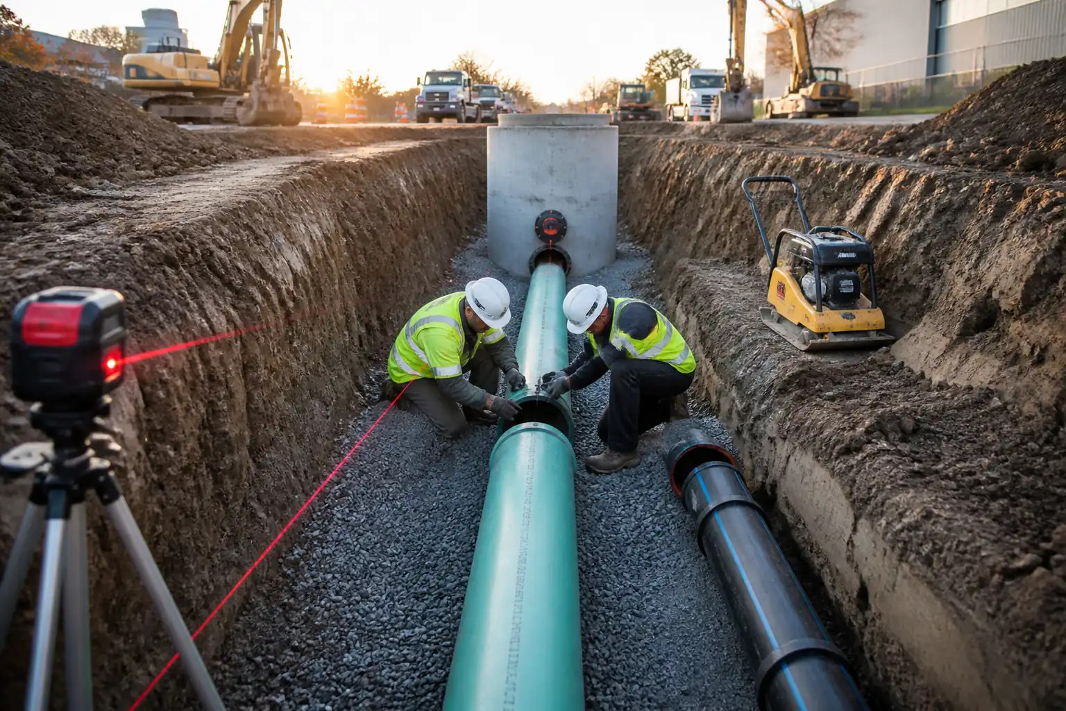
- Pipe lowering and joint assembly (push-on/gasket or mechanical joints).
- Installation of anchor (thrust) blocks at bends, tees, reducers, dead-ends, and hydrant branches.
- Initial pressure class verification vs. test pressure and operating pressure.
- Hydrostatic pressure testing (pre-commissioning) and reinstatement to safe temporary backfill level (final reinstatement by others if specified).
Exclusions/Interfaces
- Disinfection, flushing, and bacteriological testing are excluded unless stated otherwise (to be performed post-pressure test) [Verify per project specifications].
- Permanent surface reinstatement, valve chamber construction, and appurtenance installation may be covered under separate method statements if not explicitly included.
- Utility diversions and relocation works are by others unless specified.
Key Performance Requirements
- Alignment and level tolerances, bedding thickness and compaction, joint integrity, and thrust restraint adequacy to comply with referenced standards and project specifications.
- Materials, equipment, and measuring devices to be approved and calibrated.
- HSE controls and environmental protection measures implemented throughout.
References
| Document Type | Reference / Number | Revision | Notes |
|---|---|---|---|
| Standard | ISO 2531: Ductile iron pipes, fittings, accessories and their joints for water applications | ||
| Standard | EN 545: Ductile iron pipes, fittings, accessories and their joints for water pipelines — Requirements and test methods | ||
| Standard | AWWA C151/A21.51: Ductile-Iron Pipe, Centrifugally Cast | ||
| Standard | AWWA C111/A21.11: Rubber-Gasket Joints for Ductile-Iron Pressure Pipe and Fittings | ||
| Standard | AWWA C600: Installation of Ductile-Iron Water Mains and Their Appurtenances | ||
| Standard | BS EN 805: Water supply — Requirements for systems and components outside buildings | ||
| Guidance/Manual | AWWA M41: Ductile-Iron Pipe and Fittings (thrust restraint design guidance) | ||
| Standard | ASTM D698/D1557: Laboratory compaction characteristics of soil (Proctor/Modified Proctor) | ||
| Standard | ISO 4014/4017: Hex head bolts and nuts (for mechanical joints) |
Responsibilities
| Role | Responsibility | Name / Party |
|---|---|---|
| Project Manager | Project Manager | Contractor |
| Site Engineer | Site Engineer | Contractor |
| QA/QC Engineer | QA/QC Engineer | Contractor |
| Surveyor | Land Surveyor | Contractor |
| HSE Officer | HSE Officer | Contractor |
| Foreman | General Foreman | Contractor |
| Lab | Independent Laboratory | Approved Laboratory |
| Client Rep | Engineer/Client Representative | Engineer/Employer |
Resources
| Resource Type | Description | Quantity | Remarks |
|---|---|---|---|
| Manpower | Pipefitters, laborers | 7–8 persons | |
| Manpower | Appointed person, rigger/slinger, excavator operator | 3–4 persons |
Materials
| Material | Specification / Grade | Quantity | Remarks |
|---|---|---|---|
| DI Pipes (DN100–DN1200 typical) | ISO 2531 / EN 545; Class (e.g., PN16, thickness class K9 or series C) [Verify per project] | As per BOQ | Markings to show DN, PN/class, standard, heat no., manufacturer |
| Push-on gasket (EPDM) | AWWA C111 / EN 545; EN 681-1 elastomeric seals | 1 per joint + spares | Stored cool, dry, away from hydrocarbons |
| Mechanical joint glands, T-bolts, nuts, washers | AWWA C111; ISO 4014/4017; property class 8.8 or as specified [Verify] | As required | |
| Granular bedding and surround | Well-graded sand/gravel, max particle size ≤10–20 mm [Verify]; Plasticity index = 0 | As required | Moisture-conditioned to near OMC |
| Concrete for anchor (thrust) blocks | Strength class C25/30 or as designed [Verify]; 20 mm agg; slump S3 [Verify] | As per design | |
| Joint lubricant | Manufacturer’s approved potable-water grade | As required | |
| Coating repair kit/paint | EN 545 compliant touch-up system | As required | |
| Warning/detectable tape | Color/legend per project; placed ~300 mm above crown [Verify] | As required |
Equipment
| Equipment | Capacity / Type | Quantity | Inspection Required |
|---|---|---|---|
| Excavator with lifting points & quick hitch lock | 10–20 t | 1–2 | Daily pre-use; LOLER/third-party cert [Verify] |
| Web slings, shackles, spreader beam | SWL per lift plan | As required | Color-coded slings; 6-monthly inspection [Verify] |
| Trench box/shoring system | To suit trench depth/soil class | As required | Competent person inspection each shift |
| Submersible pump and hoses | ≥20–50 m³/h [Verify] | 1–2 | Electrical PAT; GFCI/RCD [Verify] |
| Plate compactor/rammer | Compaction energy to meet 95% MDD | 1 | Pre-use check |
| Laser level/auto level & staff | 1 | Calibration cert ≤12 months | |
| Torque wrench set | Range 40–300 Nm [Verify] | 1 set | Calibration cert ≤6 months |
| Pipe cutting, chamfering, coating repair tools | As required | Guarding & permits as required | |
| Hydrostatic test pump, gauges, data logger | Up to required test pressure (e.g., 16–25 bar) [Verify] | 1 set | Calibration cert ≤6 months |
Prerequisites
- Approved IFC drawings, method statement, risk assessment, and ITP available on site.
- Permits to Work (excavation, dewatering, lifting, hot works if any, traffic management) issued [Verify per project HSE plan and local regulations].
- Utility search and permits obtained; trial pits completed and services positively identified/marked; isolation/consent from utility owners if required.
- Materials MIRs approved; pipes, gaskets, fittings, and concrete mix design (if site mixed) approved; certificates of conformity (ISO 2531/EN 545) available.
- Calibration certificates for gauges, levels, torque wrenches, and test pump current and valid.
- Lifting plan approved with rigging study for longest/heaviest pipe and fittings; appointed person and riggers briefed.
- Dewatering and groundwater control plan approved, including discharge consent if applicable.
- Survey control established; benchmarks protected; trench line set out with offsets.
- Pre-start briefing/toolbox talk conducted; emergency and rescue plan tested (trench collapse, lifting incident, flooding).
- Weather and ground conditions assessed; stop work if conditions jeopardize trench stability or joint integrity.
- Thrust block design calculations signed off or standard details selected for each fitting/bend angle and test pressure.
- Test water source identified; disposal route/consent defined (avoid chlorinated discharges at this stage).
Method Sequence
| Step | Activity | Description | Responsibility | Inspection / Hold Point |
|---|---|---|---|---|
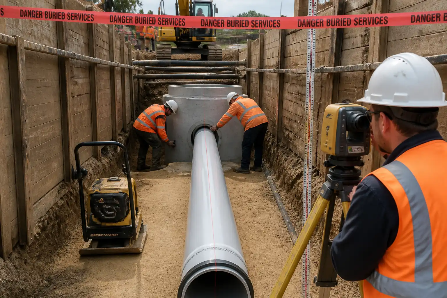
| 1 | Setting out and controls | Establish pipeline centerline and invert levels at required intervals; install profile boards/pegs outside trench line. | Surveyor/Site Engineer | Check against IFC drawings |
| 2 | Excavation and shoring | Excavate trench to design depth and width. Provide shoring/trench box per soil conditions. Manage groundwater with pumps/sumps as required. | Foreman/Site Engineer | Excavation permit; trench inspection by competent person |
| 3 | Foundation treatment | Trim trench bottom; remove loose/soft spots; replace with compacted granular material or lean concrete blinding where specified. | Foreman/Site Engineer | Engineer to inspect before bedding |
| 4 | Bedding placement | Place granular bedding uniformly (no hollows) and compact lightly to specified thickness. | Foreman | QA/QC to verify material and thickness |
| 5 | Pipe receipt and inspection | Inspect each pipe/fitting for damage, coating integrity, roundness, and cleanliness. Verify markings: DN, PN/class (e.g., PN16), standard (EN 545/ISO 2531), heat/lot numbers. | QA/QC Engineer | MIR approval; visual inspection |
| 6 | Initial pressure class verification | Confirm pipe/fitting pressure class rating vs. section design operating pressure and intended hydrostatic test pressure. | Site Engineer/QA-QC | Document review; marking verification |
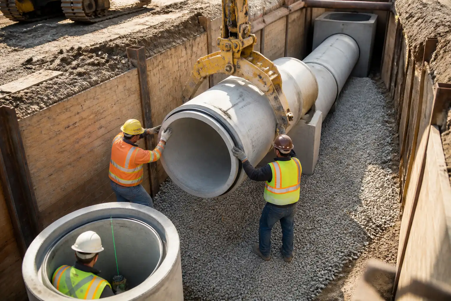
| 7 | Pipe lowering | Lift using certified slings/spreader to avoid coating damage. Lower onto bedding; prevent impact or dragging. | Foreman/Appointed Person | Lift plan compliance; banksman in control |
| 8 | Joint preparation | Clean bell and spigot; inspect and seat gasket (push-on) or prepare mechanical joint components. Apply approved lubricant to spigot/gasket as applicable. | Pipefitter/Foreman | QA/QC spot-check |
| 9 | Push-on joint assembly | Align pipes; insert spigot into bell until home mark flush with bell face using come-alongs/jacks. Do not exceed allowable deflection. | Pipefitter/Foreman | Witness by QA/QC or Engineer as required |
| 10 | Mechanical joint assembly (if specified) | Install gasket, gland, and T-bolts; tighten in star pattern in stages using calibrated torque wrench. | Pipefitter/Foreman | Torque verification |
| 11 | Coating repairs | Repair any coating damage per manufacturer’s kit instructions; allow curing before backfill. | Foreman/QA-QC | Visual and DFT (if specified) |
| 12 | Anchor (thrust) blocks | Excavate behind fitting to undisturbed ground; install form/earth form; place concrete to designed dimensions and bearing area oriented perpendicular to resultant thrust; isolate bolts/glands from concrete. | Site Engineer/Foreman | Hold/Witness point prior to pour |
| 13 | Initial backfill (haunching and surround) | Place and compact granular surround to springline and then to ≥300 mm above crown in layers ≤150 mm. | Foreman | QA/QC to check material and compaction |
| 14 | Warning tape placement | Install warning/detectable tape along trench. | Foreman | Visual |
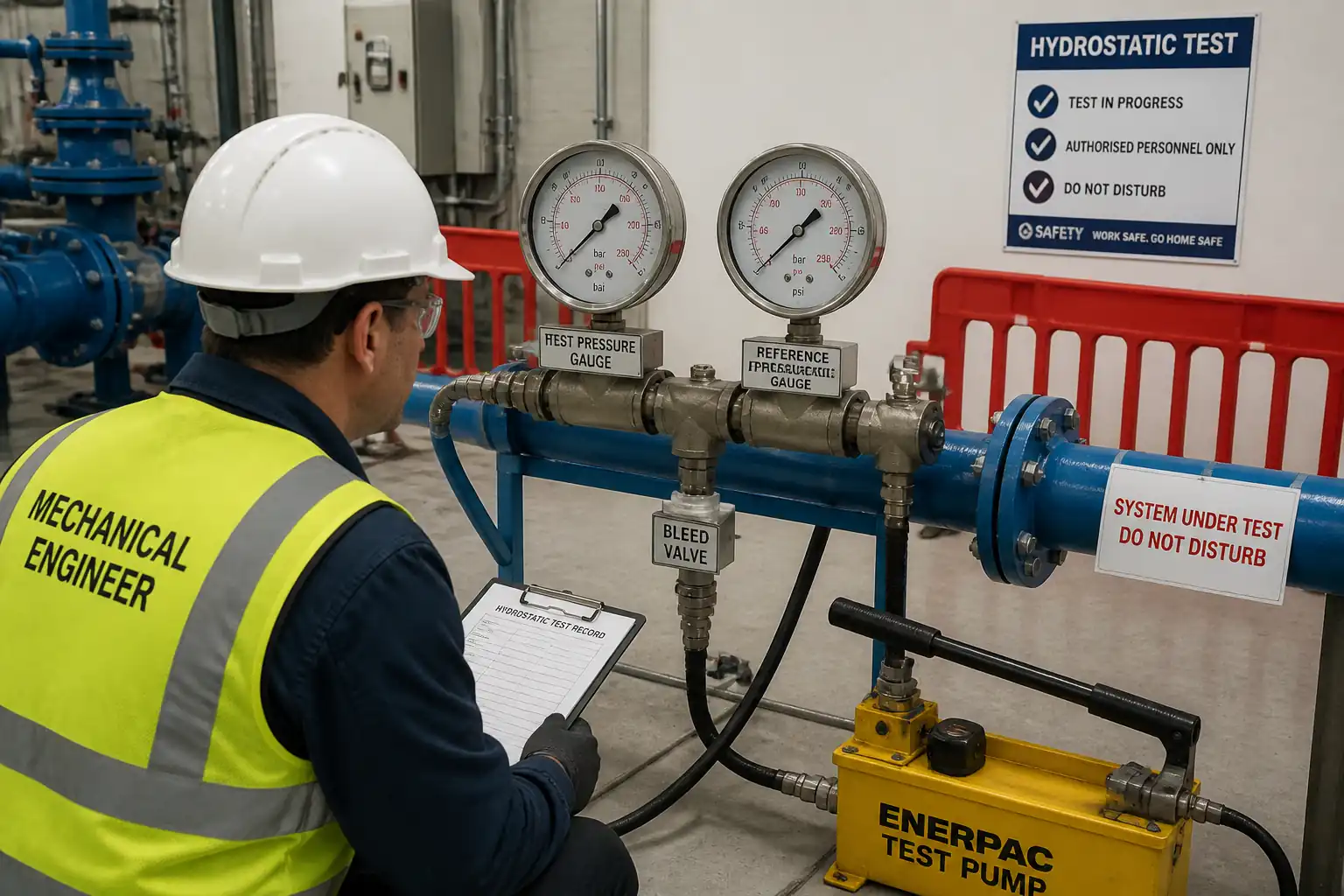
| 15 | Sectional pressure test preparation | Install temporary end caps, test manifold, calibrated gauges; provide air release points at high points; slowly fill from low point and expel air; soak period for mortar lining. | Site Engineer/QA-QC | Calibration certificates; pre-test checklist |
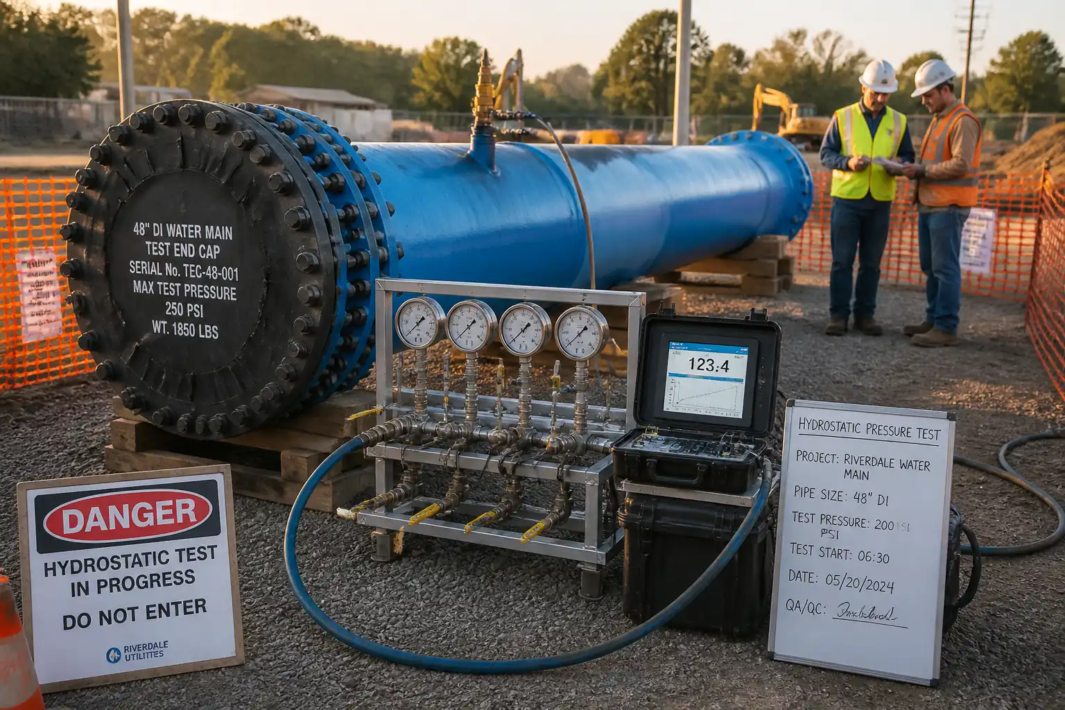
| 16 | Hydrostatic pressure test | Raise pressure to specified test pressure and hold; measure makeup water to maintain pressure; record pressure/time/leakage. | QA/QC Engineer | Engineer witness as per ITP |
| 17 | Post-test works | Depressurize slowly; drain to approved discharge; reinstate temporary backfill to safe level; remove test fittings; install permanent fittings/gaskets as required. | Foreman/Site Engineer | Environmental consent compliance |
Health, Safety and Environment (HSE) — Safety Controls
Identify, assess, and control the following task-specific hazards:
- Hazard: Trench collapse/engulfment
- Likely consequence: Serious injury/fatality by burial or crushing
- Engineering/procedural control: Design shoring/trench boxes to suit soil class and depth; keep surcharge loads/set plant ≥1 m from edge; step/bench where allowed; daily inspections by competent person; install safe access/egress every ≤7.5 m [Verify per local code]
- Required PPE: Helmet with chin strap, high-visibility vest, safety boots, gloves
- Collective preventive measure: Physical barriers, guardrails, trench edge stop blocks, exclusion zones
-
Inspection/permit/supervision: Excavation permit; daily trench inspection record; appointed competent person sign-off
-
Hazard: Underground utility strike (gas, power, telecom)
- Likely consequence: Electrocution, explosion, service outage
- Engineering/procedural control: Utility maps + electronic locating + trial pits; hand-dig in tolerance zones; maintain minimum clearances; liaison with utility owners; live services support; permit to dig
- Required PPE: Dielectric gloves when appropriate, insulated tools near electrical
- Collective preventive measure: Marked corridors, barriers, spotter
-
Inspection/permit/supervision: Permit-to-dig; supervision by Site Engineer
-
Hazard: Lifting and lowering pipes/fittings
- Likely consequence: Crush injuries, dropped loads, rigging failure
- Engineering/procedural control: Approved lift plan; use spreader bars/web slings (no chains on coating); tag lines; controlled communication; wind limits [Verify]; no personnel under suspended load
- Required PPE: Helmets, steel-toe boots, gloves, eye protection
- Collective preventive measure: Exclusion zones, banksman control, spotters
-
Inspection/permit/supervision: Lifting equipment certification; pre-lift checklist; Appointed Person and competent operator on site
-
Hazard: Working in/near water and dewatering operations
- Likely consequence: Slips, drowning in sumps, electrocution (pumps)
- Engineering/procedural control: Secure pump cables/hoses; GFCI/RCD protection; covered sumps; non-slip access; emergency plan for flooding
- Required PPE: Waterproof boots, gloves; life jacket if near deep water
- Collective preventive measure: Barriers around sumps; spill kits
-
Inspection/permit/supervision: Electrical PAT; weekly pump checks
-
Hazard: Pressurization and hydrostatic testing
- Likely consequence: Pipe/joint burst, projectile end caps, high-energy release
- Engineering/procedural control: Verify end restraints/thrust blocks strength and curing; rated test end caps; exclusion zone during pressurization; pressure increase gradual; calibrated gauges; relief valve
- Required PPE: Eye/face protection, helmet, gloves
- Collective preventive measure: Barriers and signage; remote monitoring where possible
-
Inspection/permit/supervision: Test permit; Engineer witness; test log
-
Hazard: Manual handling and musculoskeletal strain
- Likely consequence: Sprains/strains
- Engineering/procedural control: Team lifts; use dollies/rollers; rotate tasks
- Required PPE: Gloves, supportive footwear
- Collective preventive measure: Mechanical aids
-
Inspection/permit/supervision: Supervisor oversight; training records
-
Hazard: Traffic interface (public roads/site plant)
- Likely consequence: Struck-by incidents
- Engineering/procedural control: Traffic Management Plan; segregated routes; banksman; work during off-peak where feasible
- Required PPE: High-visibility clothing, helmets
- Collective preventive measure: Barriers, signage, lighting at night
-
Inspection/permit/supervision: Road opening permit; daily checks; [Verify per local authority]
-
Hazard: Silica dust and noise from cutting/compaction
- Likely consequence: Respiratory and hearing damage
- Engineering/procedural control: Wet cutting; dust suppression; use quieter plant; exposure time limits
- Required PPE: FFP2/FFP3 mask as needed, hearing protection, eye protection
- Collective preventive measure: Water suppression units; acoustic screens where practicable
-
Inspection/permit/supervision: Noise monitoring if required; COSHH assessments [Verify]
-
Hazard: Contact with cement/concrete for thrust blocks
- Likely consequence: Chemical burns/dermatitis
- Engineering/procedural control: Avoid skin contact; wash stations; correct mixing; safe delivery access
- Required PPE: Alkali-resistant gloves, long sleeves, goggles
- Collective preventive measure: Barriers around fresh concrete
- Inspection/permit/supervision: Material SDS on site; supervision during pour
Where exact legal requirements apply, implement them in addition to the above [Verify per project HSE plan and local regulations].
Environmental Controls
- Groundwater and surface water management:
- Dewatering discharge via silt bags or settlement tanks; obtain discharge consent if needed. Prevent trench fines from entering watercourses.
-
Maintain pumps to prevent leaks; place drip trays under generators/pumps.
-
Spoil and material handling:
-
Segregate reusable granular material from unsuitable spoil. Stockpile outside root protection zones and away from drains. Cover dusty stockpiles in dry/windy conditions.
-
Noise and vibration:
-
Use compliant equipment; restrict high-noise activities to permitted hours; monitor if near sensitive receptors [Verify per local consent].
-
Dust and air quality:
-
Water spray during cutting/backfilling; speed control on haul routes; wheel-wash as required.
-
Concrete works:
-
Use lined washout; no washout into ground or drainage. Collect and dispose of hardened waste via licensed facilities.
-
Water for hydrostatic testing:
-
Source from approved hydrant or tanker; measure volumes. Discharge only clean, non-chlorinated water to approved points; use energy dissipation to prevent erosion.
-
Waste management:
-
Collect gasket/bolt packaging; recycle metals where possible. Dispose of contaminated materials via licensed carrier with waste transfer notes.
-
Ecology and heritage:
-
Stop work and notify if protected species or archaeological finds encountered. Follow project-specific method statements if in sensitive areas.
-
Monitoring and records:
- Keep environmental log (pumping hours, discharge turbidity if required, complaints register). Corrective actions tracked to close-out.
Quality Assurance / Quality Control
- Standards and acceptance:
-
Installation complies with ISO 2531/EN 545, AWWA C600, and project specifications.
-
Tolerances:
- Alignment: ±50 mm horizontal; Level: ±20 mm vertical [Verify per project].
- Bedding thickness: 100–150 mm, tolerance ±10 mm [Verify].
- Surround compaction: ≥95% MDD (ASTM D698) unless specified otherwise.
- Joint deflection: within manufacturer’s published limits (typically 1–3° for push-on joints) [Verify].
-
Coating repairs: DFT per product datasheet; no bare metal exposed.
-
Thrust/anchor blocks:
- Bearing area sized using test/design pressure, pipe area, and fitting angle; allowable soil bearing from geotechnical data [Verify].
-
Concrete class and curing meet design; no testing before minimum strength achieved.
-
Pressure testing:
- Gauges and test pump calibrated within 6 months; dual gauges cross-checked.
- Soak period observed for cement mortar lining (typically ≥24 h) [Verify].
-
Test pressure and duration per spec (typ. 1.25–1.5 × operating pressure, 2 h) within pipe class limits; acceptable leakage per AWWA C600 formula. No visible leaks permitted.
-
Records and traceability:
- Material certificates, heat numbers, and lot traceability maintained.
- ITP sign-offs at each hold/witness point.
-
As-built drawings with chainages, valve/hydrant locations, and changes recorded daily.
-
Nonconformance and corrective action:
- NCR raised for deviations; corrective works agreed with Engineer; re-test/re-inspect as required.
Attachments
- Typical trench and bedding detail (sketch) with dimensions and tolerances.
- Standard thrust/anchor block details for bends (11.25°, 22.5°, 45°, 90°), tees, reducers, and dead ends, including calculation template.
- Manufacturer torque tables for mechanical joints by DN size.
- Lifting plan and rigging diagram for longest pipe section.
- Pre-start checklist and daily trench inspection form.
- Hydrostatic pressure test procedure and data sheet, including leakage calculation sheet (AWWA C600 formula and metric conversion guide).
- Material submittal approvals and certificates (ISO 2531/EN 545 compliance).
- Calibration certificates (gauges, torque wrenches, levels, test pump).
- Environmental management plan excerpts (dewatering/discharge method).
- Emergency response plan for trench collapse and pressure testing incidents.
This content is a read-only public reference. Download or customize to get an editable version.
ITP preview
The first inspection activities from the linked ITP for Method Statement: Laying of Ductile Iron (DI) Water Main Pipes with Bedding, Joint Assembly, Anchor Blocks, and Initial Pressure Class Verification:
| Activity | Inspection / Test | Acceptance Criteria | Responsibility | Record |
|---|---|---|---|---|
| Approvals and permits | Verify approvals: MS, ITP, RA, permits to dig/lift/dewater | All approvals/permits current and applicable | PM / HSE / Site Engineer | Approved MS/ITP, PTWs filed |
| Material receiving (pipes, gaskets, fittings) | Check certificates, markings (DN, PN/class, standard), condition | Compliant with ISO 2531/EN 545; no damage; correct class | QA/QC Engineer | MIR; ITR-MAT-01 |
| Trench excavation and base | Dimensions, stability/shoring, base condition | Width/depth within tolerance; base firm, level; dewatering effective | Site Engineer / QA/QC | ITR-EXC-01/02 |
Showing 3 of 12 inspection activities. View full ITP →
Related Inspection and Test Plan
An Inspection and Test Plan (ITP) is available for Method Statement: Laying of Ductile Iron (DI) Water Main Pipes with Bedding, Joint Assembly, Anchor Blocks, and Initial Pressure Class Verification. The ITP defines the inspection activities, acceptance criteria, hold and witness points, responsible parties, and records required to verify the work described in this method statement.
View the Method Statement: Laying of Ductile Iron (DI) Water Main Pipes with Bedding, Joint Assembly, Anchor Blocks, and Initial Pressure Class Verification ITP →Frequently asked questions
Continue with related Quollnet resources connected to this method statement.