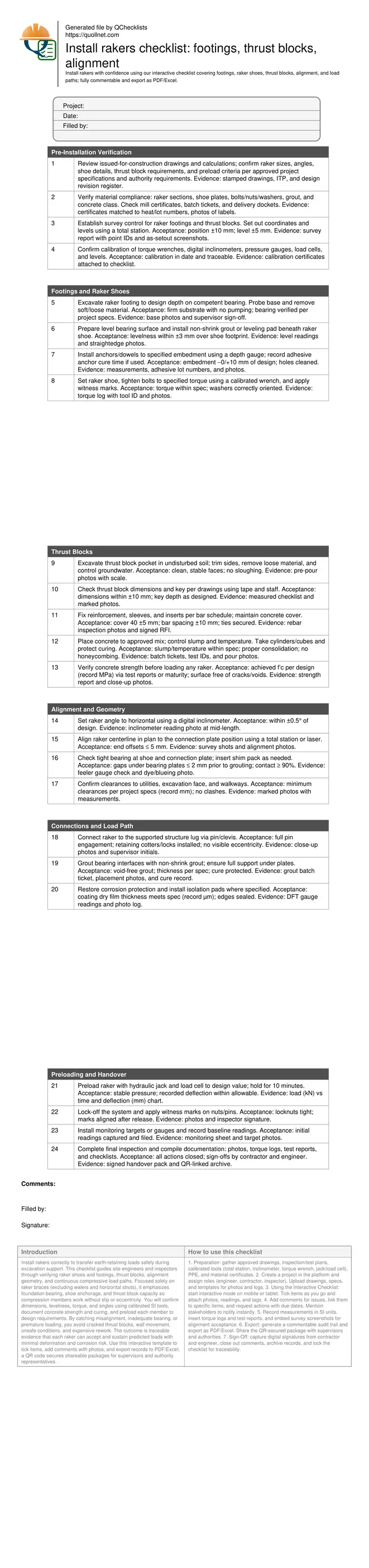
Install rakers checklist: footings, thrust blocks, alignment
Definition: Install rakers checklist for site engineers and inspectors verifying footings, raker shoes, thrust blocks, alignment, and load paths, ensuring compliant installation per approved project specifications and authority requirements.
- Verify foundations, shoes, thrust blocks, and alignment transfer design loads safely.
- Measure geometry, levelness, torque, and bearing using calibrated SI-based tools.
- Document load paths, preload results, photos, and approvals with traceable evidence.
- Interactive, commentable checklist; export, share, and authenticate via QR code.
Install rakers correctly to transfer earth-retaining loads safely during excavation support. This checklist guides site engineers and inspectors through verifying raker shoes and footings, thrust blocks, alignment geometry, and continuous compressive load paths. Focused solely on raker braces (excluding walers and horizontal struts), it emphasizes foundation bearing, shoe anchorage, and thrust block capacity so compression members work without slip or eccentricity. You will confirm dimensions, levelness, torque, and angles using calibrated SI tools, document concrete strength and curing, and preload each member to design requirements. By catching misalignment, inadequate bearing, or premature loading, you avoid cracked thrust blocks, wall movement, unsafe conditions, and expensive rework. The outcome is traceable evidence that each raker can accept and sustain predicted loads with minimal deformation and corrosion risk. Use this interactive template to tick items, add comments with photos, and export records to PDF/Excel; a QR code secures shareable packages for supervisors and authority representatives.
- Ensure raker shoes and footings provide reliable bearing with level, grouted interfaces and correctly torqued anchors, preventing slip or eccentric loading that can crack concrete or induce wall movement during staged excavation and support activities.
- Build thrust blocks in undisturbed soil with correct dimensions, reinforcement, and curing. Confirm concrete strength before loading, and eliminate voids or honeycombing to maintain full compressive capacity and predictable load transfer along the designed path.
- Hold alignment and angle tolerances with precision instruments. Verify angle within ±0.5°, offsets within millimetres, and full contact at bearing plates to minimize deformation, reduce unintended bending, and ensure rakers act as compression members only.
- Interactive online checklist with tick, comment, and export features secured by QR code. Capture photos, measurements, torque logs, and test reports, then generate authenticated PDF/Excel packages for fast sign-off per approved project specifications and authority requirements.
Pre-Installation Verification
Footings and Raker Shoes
Thrust Blocks
Alignment and Geometry
Connections and Load Path
Preloading and Handover
Footings and raker shoes: getting the bearing right
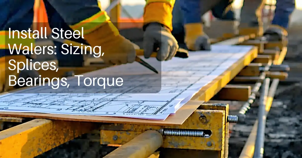
Raker shoes and their footings are the first safeguards against slip and eccentricity. A clean, level, and firm bearing surface prevents stress concentrations and keeps compression loads aligned with the raker’s axis. Begin by excavating to the specified depth on competent material, removing soft pockets, and controlling groundwater. Install anchors or dowels to the correct embedment, and place a leveling grout pad so the shoe sits within a few millimetres of level. Tighten bolted connections with calibrated torque wrenches and mark them to reveal post-loading movement. Before moving on, verify the bearing interface under the shoe covers at least ninety percent of the plate area, with any remaining local gaps shimmed and regrouted. These seemingly small tasks—levelness, torque, and contact—dramatically reduce unintended bending and joint movement when the raker is preloaded. Capture photos, measurements, and torque logs to create traceable evidence that the base can reliably transfer compressive loads into the ground without crushing or sliding.
- Levelness within ±3 mm across the shoe footprint
- Anchors installed to −0/+10 mm embedment tolerance
- Torque recorded with calibrated wrench and witness marks
- Bearing contact area ≥ 90% before final grouting
Thrust blocks that resist and last
A well-built thrust block transforms the raker’s axial force into soil resistance without crushing or excessive settlement. Excavate the pocket in undisturbed soil, trim faces clean, and include a key or shear feature where shown. Fit reinforcement and sleeves to the bar schedule, maintaining consistent cover to protect steel from corrosion and ensure bond. Place concrete of the approved class, consolidating to eliminate voids, and protect curing with wet coverings or curing compounds. Do not preload or lock any raker into the block until the concrete achieves the specified compressive strength; verify via cylinder or cube tests, or maturity curves. Inspect for honeycombing and cracks, and rework deficient areas before loading. A thrust block that meets dimension, cover, and strength requirements provides dependable capacity and limits movements at the supported structure during staged excavation, minimizing risk to adjacent assets and reducing rework.
- Dimensions within ±10 mm; key depth per design
- Concrete class and test IDs recorded and stored
- Cover 40 ±5 mm; reinforcement fixed and tied
- No honeycombing; surfaces cured and protected
Alignment and load path: compressive, straight, and stable
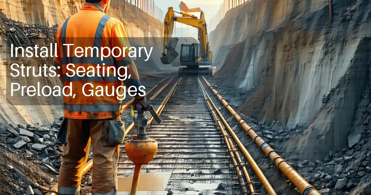
Rakers must work as pure compression members. Set the design angle with a digital inclinometer and confirm plan alignment using a total station so the connection pin sits true and centered. Verify tight bearing at both ends, shim where needed, and grout to remove gaps; incomplete contact creates stress risers and unwanted bending. During preloading, use a hydraulic jack and load cell to reach the target load, holding it while monitoring deflection at the supported structure. Deflections that stabilize within allowable limits indicate a sound load path; abrupt pressure drops or excessive movement point to bedding issues, inadequate thrust block strength, or joint slip. After lock-off, apply witness marks and establish baseline monitoring readings so any shift becomes obvious during subsequent excavation stages. Document every measurement with photos and logs to provide a clear, defensible record of geometry, preload, and performance.
- Angle within ±0.5° of design using inclinometer
- Plan offset ≤ 5 mm confirmed by survey
- Bearing gaps ≤ 2 mm before grouting
- Preload held 10 minutes with stable readings
- Baseline monitoring readings captured and filed
How to use this raker installation checklist
- Preparation: gather approved drawings, inspection/test plans, calibrated tools (total station, inclinometer, torque wrench, jack/load cell), PPE, and material certificates.
- Create a project in the platform and assign roles (engineer, contractor, inspector). Upload drawings, specs, and templates for photos and logs.
- Using the Interactive Checklist: start interactive mode on mobile or tablet. Tick items as you go and attach photos, readings, and tags.
- Add comments for issues, link them to specific items, and request actions with due dates. Mention stakeholders to notify instantly.
- Record measurements in SI units, insert torque logs and test reports, and embed survey screenshots for alignment acceptance.
- Export: generate a commentable audit trail and export as PDF/Excel. Share the QR-secured package with supervisors and authorities.
- Sign-Off: capture digital signatures from contractor and engineer, close out comments, archive records, and lock the checklist for traceability.
Call to Action
- Start Checklist Tick off tasks, leave comments on items or the whole form, and export your completed report to PDF or Excel—with a built-in QR code for authenticity.
- Download Excel - Raker Installation Inspection
- Download PDF - Raker Installation Inspection
- View Image - Raker Installation Inspection
Cite & Embed
“Raker Installation Inspection by Quollnet”
with a link to
this source page.

FAQ
Question: What defines a compliant raker installation?
Question: What tolerances should I hold on angle and geometry?
Question: When is it safe to preload a raker after casting the thrust block?
Question: How do I demonstrate a continuous load path without eccentricity?
Related Articles
Broader reading and guidance connected to this checklist topic.

Download Excel Format Snag List

Is It Important To Customize Your Qr Code And How To Do It?
Is The Crack You See On Your Wall Serious Or Minor Cosmetic Issue?

Related Checklists
Keep the workflow moving with nearby templates chosen from similar checklist content.