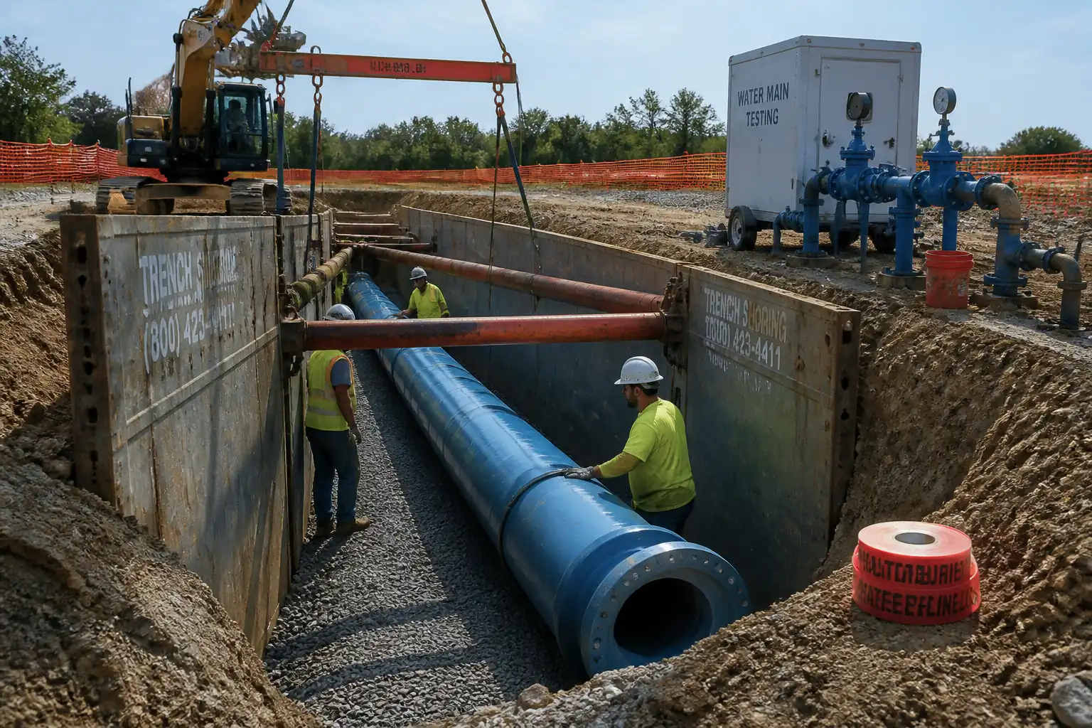
Inspection and Test Plan for Method Statement: Laying of Ductile Iron (DI) Water Main Pipes with Bedding, Joint Assembly, Anchor Blocks, and Initial Pressure Class Verification
AI-assisted inspection and test plan connected to a method statement, with PDF and Excel export.
More than a static template
Unlike a downloadable Word or PDF template, this ITP is an AI-assisted editable starting point directly connected to its method statement. Every inspection activity, hold point, and acceptance criterion is structured and ready to adapt to your project.
- AI-assisted customization — Tailor inspection activities and acceptance criteria to your specific project scope.
- Linked method statement — This ITP is connected to the corresponding method statement describing the work sequence.
- Multiple export formats — Download as a formatted PDF or editable Excel spreadsheet.
- Editable starting point, not a final document — Review and verify all content against your project specifications and standards before use.
What you can customize
When you save this ITP to your account, every inspection row becomes editable. You can add, remove, or modify:
- Inspection activity — Description of what is being inspected.
- Inspection type — Hold point (H), Witness point (W), Review (R), or Monitor (M).
- Responsibility — Contractor, subcontractor, engineer, or client.
- Frequency — How often the inspection occurs.
- Acceptance criteria — Referenced standard or specification requirement.
- Records — Forms, test reports, or checklists required as evidence.
Why this ITP is used
To ensure every installation and testing step is verified against standards and project specifications before proceeding.
Who uses this inspection and test plan
Contractor QA/QC, Site Engineer, Client/Engineer Representatives, and independent laboratories.
When this ITP is prepared and submitted
From material receipt to final hydrostatic testing and documentation handover for each pipeline section.
Who receives or approves this ITP
Engineer/Client Representative for approval prior to works.
Inspection scope
Material verification, trench and bedding, joint assembly, thrust blocks, backfill compaction, and hydrostatic test witnessing.
Typical hold, witness, and review points
Hold: trench base before bedding; thrust block form/bearing prior to pour; hydrostatic test start. Witness: joint assembly, compaction tests, pressure test hold.
Typical inspection records
MIRs, ITRs, compaction and concrete test results, torque logs, pressure test data, calibration certificates, and as-built drawings.
Important approval note
This ITP is an AI-assisted editable starting point, not a pre-approved document. Before use on any project, all inspection activities, hold points, and acceptance criteria must be reviewed and approved by the relevant parties (superintendent, principal contractor, or client representative) in accordance with your contract and project quality plan.
Always verify acceptance criteria against your applicable drawings, specifications, and regulatory requirements. Hold points must be confirmed with the relevant authority before work proceeds past that point.
Inspection and test plan
| Activity | Inspection / Test | Acceptance Criteria | Responsibility | Record |
|---|---|---|---|---|
| Approvals and permits | Verify approvals: MS, ITP, RA, permits to dig/lift/dewater | All approvals/permits current and applicable | PM / HSE / Site Engineer | Approved MS/ITP, PTWs filed |
| Material receiving (pipes, gaskets, fittings) | Check certificates, markings (DN, PN/class, standard), condition | Compliant with ISO 2531/EN 545; no damage; correct class | QA/QC Engineer | MIR; ITR-MAT-01 |
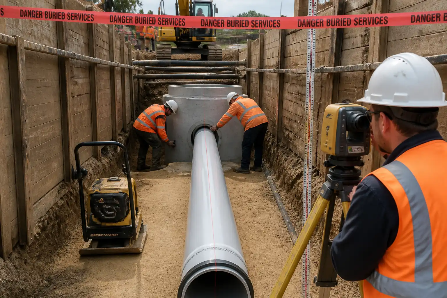
| Trench excavation and base | Dimensions, stability/shoring, base condition | Width/depth within tolerance; base firm, level; dewatering effective | Site Engineer / QA/QC | ITR-EXC-01/02 |
| Bedding placement/compaction | Material grading/PI; thickness; field density tests | Thickness 100–150 mm; ≥95% MDD [Verify] | QA/QC / Foreman | ITR-BED-01; FDT reports |
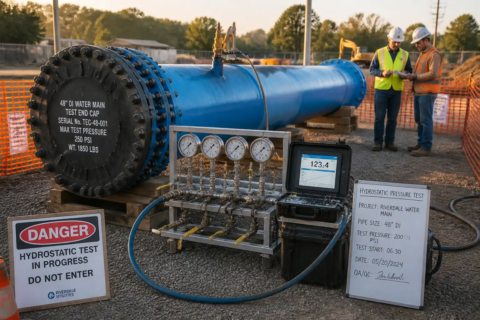
| Pipe inspection and class verification | Visual condition; marking check; calculation vs. design/test pressure | Correct PN/class; suitable for test pressure; no defects | QA/QC / Site Engineer | ITR-CLS-01; MIR |
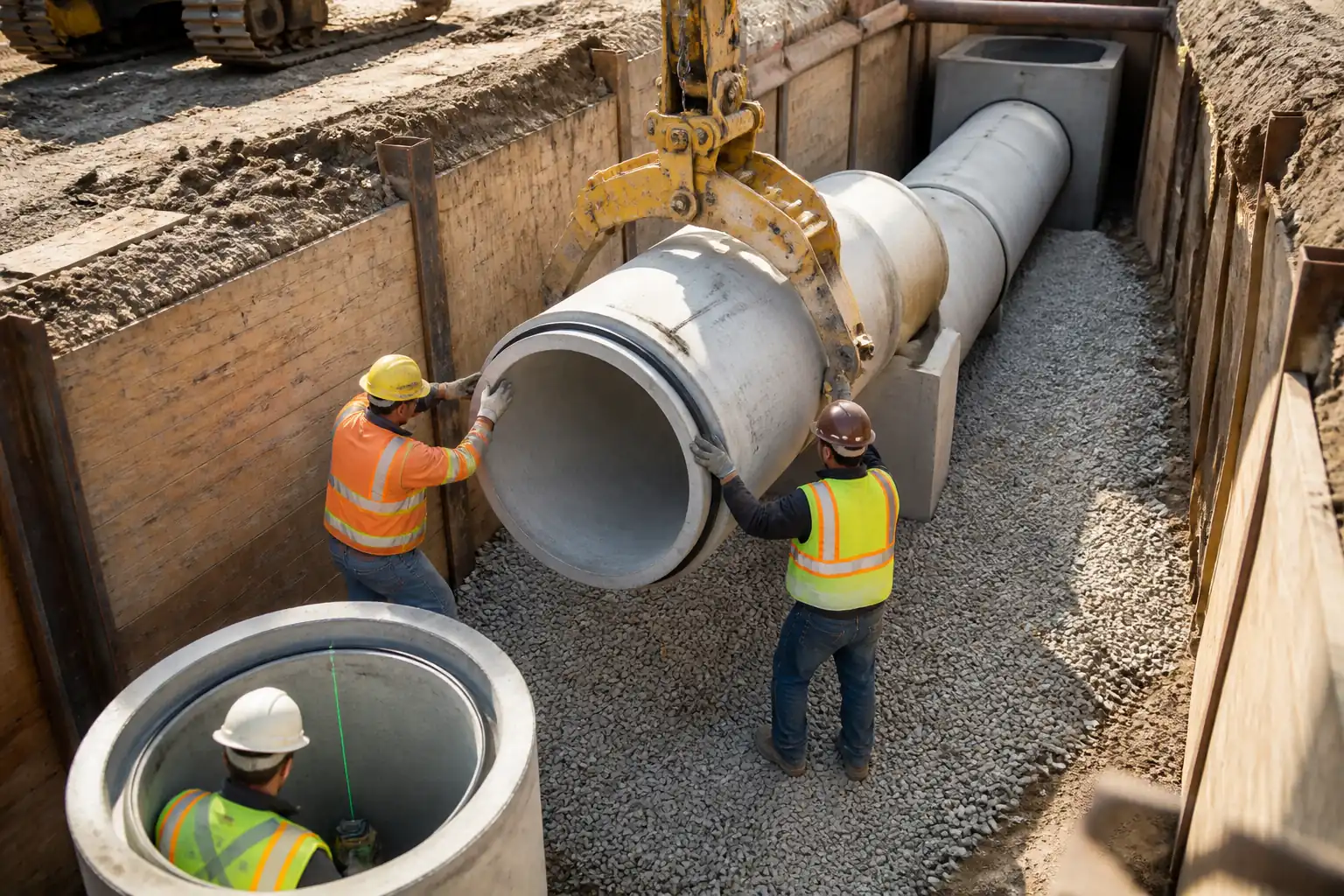
| Joint assembly (push-on) | Cleanliness, gasket seating, insertion to home mark | Home mark achieved; deflection ≤ manufacturer limit | Foreman / QA/QC | ITR-JNT-02 |
| Joint assembly (mechanical) | Bolt torque in star pattern; final torque check | Torque per size/manufacturer table [Verify] | Foreman / QA/QC | TL-MJ-01; ITR-JNT-03 |
| Coating repair (if needed) | DFT measurement; holiday detection if specified | Within datasheet limits; continuity restored | QA/QC | Coating repair log; ITR-CRT-01 |
| Anchor (thrust) blocks | Dimensions, bearing area, orientation, curing status | Per approved calc/drawing; no encasement of joints/bolts; min strength before test | Site Engineer / QA/QC | ITR-THR-01; Concrete tickets; cube tests (if specified) |
| Initial backfill/surround | Material, layer thickness, density tests | Granular surround to ≥300 mm above crown; ≥95% MDD [Verify] | QA/QC / Foreman | ITR-BKF-01; FDT reports |
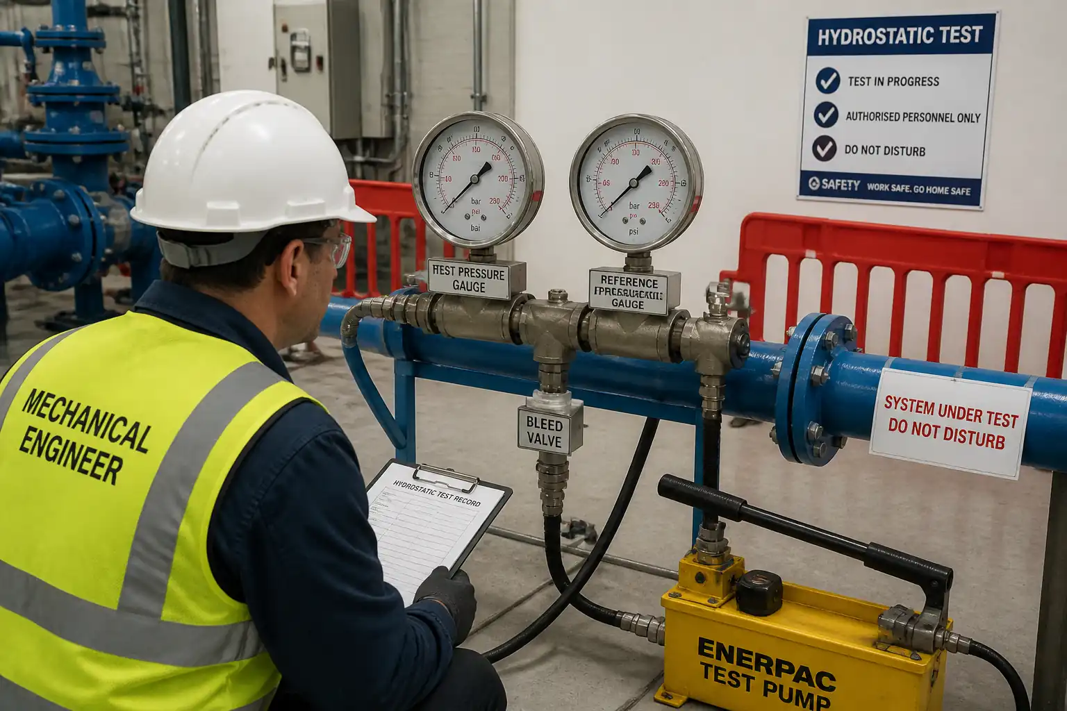
| Hydrostatic pressure test | Hold pressure for duration; record leakage/makeup water | Test pressure/duration per spec; leakage ≤ AWWA C600 allowable; no visible leaks | QA/QC / Engineer Witness | Pressure test report; gauge certs; logs |
| As-builts and records | Check completeness of documentation | All ITP points closed; redlines complete; handover pack compiled | Site Engineer / QA/QC | Handover dossier (MIRs, ITRs, test reports, as-builts) |
This table is a read-only public reference. Download the PDF or Excel version, or customize this ITP to edit it for your project.
Frequently asked questions
Related method statement
This Inspection and Test Plan is associated with the Method Statement: Laying of Ductile Iron (DI) Water Main Pipes with Bedding, Joint Assembly, Anchor Blocks, and Initial Pressure Class Verification method statement, which describes the step-by-step construction sequence, resources, materials, equipment, safety controls, and environmental controls for this activity.
View the Method Statement: Laying of Ductile Iron (DI) Water Main Pipes with Bedding, Joint Assembly, Anchor Blocks, and Initial Pressure Class Verification method statement →Continue with related inspection, method statement, article, and checklist resources.