
Inspection and Test Plan for Method Statement: Installation of Underground uPVC/HDPE Gravity Drainage Networks
AI-assisted inspection and test plan connected to a method statement, with PDF and Excel export.
More than a static template
Unlike a downloadable Word or PDF template, this ITP is an AI-assisted editable starting point directly connected to its method statement. Every inspection activity, hold point, and acceptance criterion is structured and ready to adapt to your project.
- AI-assisted customization — Tailor inspection activities and acceptance criteria to your specific project scope.
- Linked method statement — This ITP is connected to the corresponding method statement describing the work sequence.
- Multiple export formats — Download as a formatted PDF or editable Excel spreadsheet.
- Editable starting point, not a final document — Review and verify all content against your project specifications and standards before use.
What you can customize
When you save this ITP to your account, every inspection row becomes editable. You can add, remove, or modify:
- Inspection activity — Description of what is being inspected.
- Inspection type — Hold point (H), Witness point (W), Review (R), or Monitor (M).
- Responsibility — Contractor, subcontractor, engineer, or client.
- Frequency — How often the inspection occurs.
- Acceptance criteria — Referenced standard or specification requirement.
- Records — Forms, test reports, or checklists required as evidence.
Why this ITP is used
To ensure all construction and testing stages comply with standards and project specs, with traceable inspections and records.
Who uses this inspection and test plan
Contractor QA/QC, Site Engineer, HSE, Independent Test Agency, and the Engineer/Client Representative.
When this ITP is prepared and submitted
From pre-start permitting through materials receipt, trenching, installation, testing, CCTV, and handover.
Who receives or approves this ITP
Engineer/Client Representative for review and approval.
Inspection scope
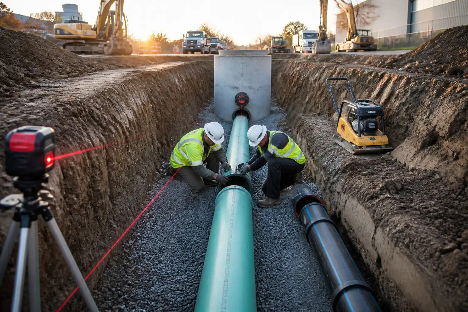
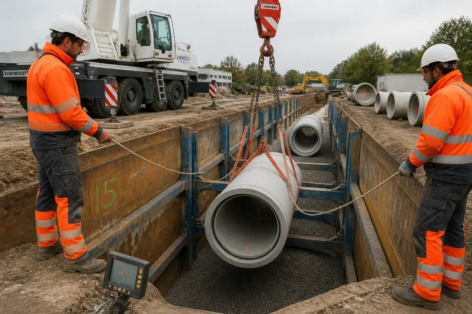
Permits, materials, excavation/support, bedding, pipe laying/jointing, manhole connections, backfilling/compaction, leakage/deflection tests, CCTV, as-builts.
Typical hold, witness, and review points
Hold: Permit to Dig, formation approval, manhole connections, leakage test. Witness: bedding placement, pipe jointing, compaction tests, CCTV.
Typical inspection records
Permits, delivery inspections, IRs, weld logs, calibration certs, density reports, EN 1610 test certificates, CCTV reports, as-built drawings.
Important approval note
This ITP is an AI-assisted editable starting point, not a pre-approved document. Before use on any project, all inspection activities, hold points, and acceptance criteria must be reviewed and approved by the relevant parties (superintendent, principal contractor, or client representative) in accordance with your contract and project quality plan.
Always verify acceptance criteria against your applicable drawings, specifications, and regulatory requirements. Hold points must be confirmed with the relevant authority before work proceeds past that point.
Inspection and test plan
| Activity | Inspection / Test | Acceptance Criteria | Responsibility | Record |
|---|---|---|---|---|
| Permits and pre-start checks | Permit to Dig, TMP, TWD approvals | All approvals in place and valid; briefings completed | PM / HSE / QA-QC | Approved permits, TBT records |
| Materials receipt (pipes, gaskets, cement) | Visual, documentation review | Compliant markings; no damage; valid certs/shelf life | QA-QC | MIR, delivery photos |
| Survey setting out | Level/line checks | Within stated tolerances | Site Engineer / Surveyor | Set-out records |
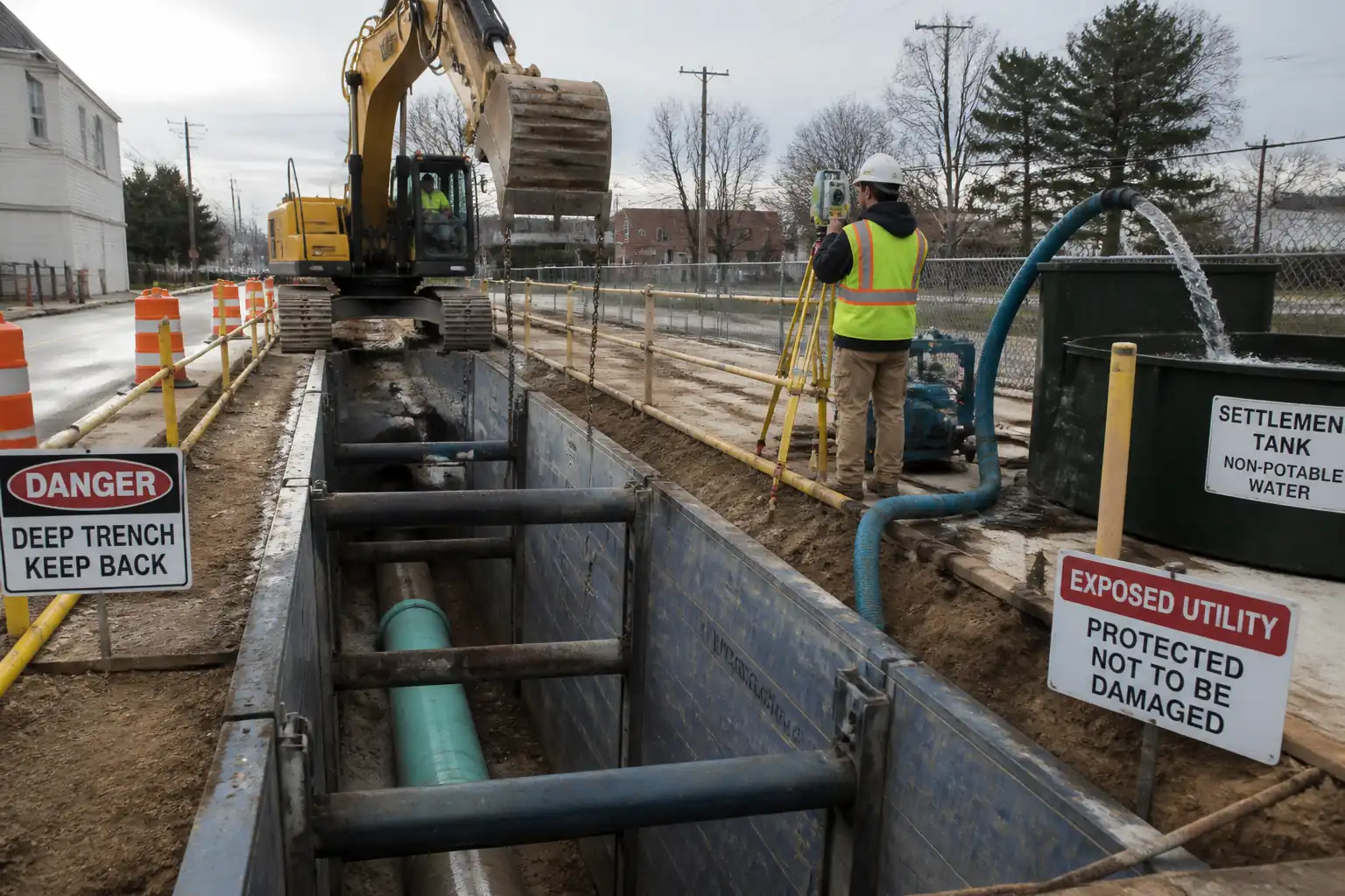
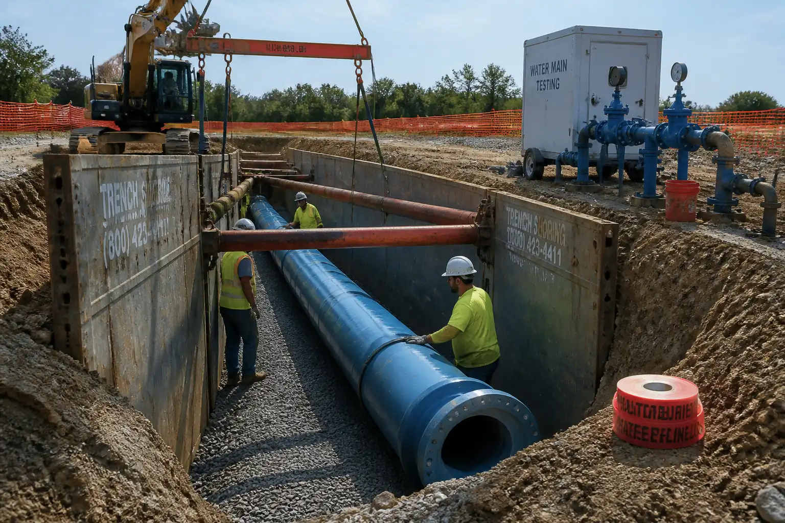
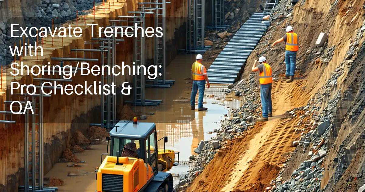
| Excavation and trench support | Dimensions and shoring inspection | Trench width/depth per design; shoring installed per TWD | Foreman / HSE | IR, photos |
| Formation approval | Visual/proof roll | Firm, level, corrected soft spots | QA-QC / Engineer | IR |
| Bedding installation | Thickness and level check | ≥100 mm, level within ±10 mm, correct material | QA-QC / Site Engineer | IR |
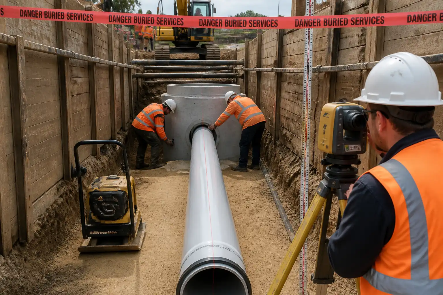
| Pipe laying and jointing (uPVC push-fit) | Insertion depth, gasket condition | Fully homed; no gasket damage; alignment acceptable | QA-QC / Foreman | Checklist |
| uPVC solvent weld joints (if used) | Visual; cure verification | Uniform bead; cure time observed | QA-QC | Joint log |
| HDPE fusion joints | Weld log, bead profile, equipment calibration | Within ISO 21307/ASTM F2620 parameters; acceptable bead | Fusion Technician / QA-QC | Weld reports, calibration certs |
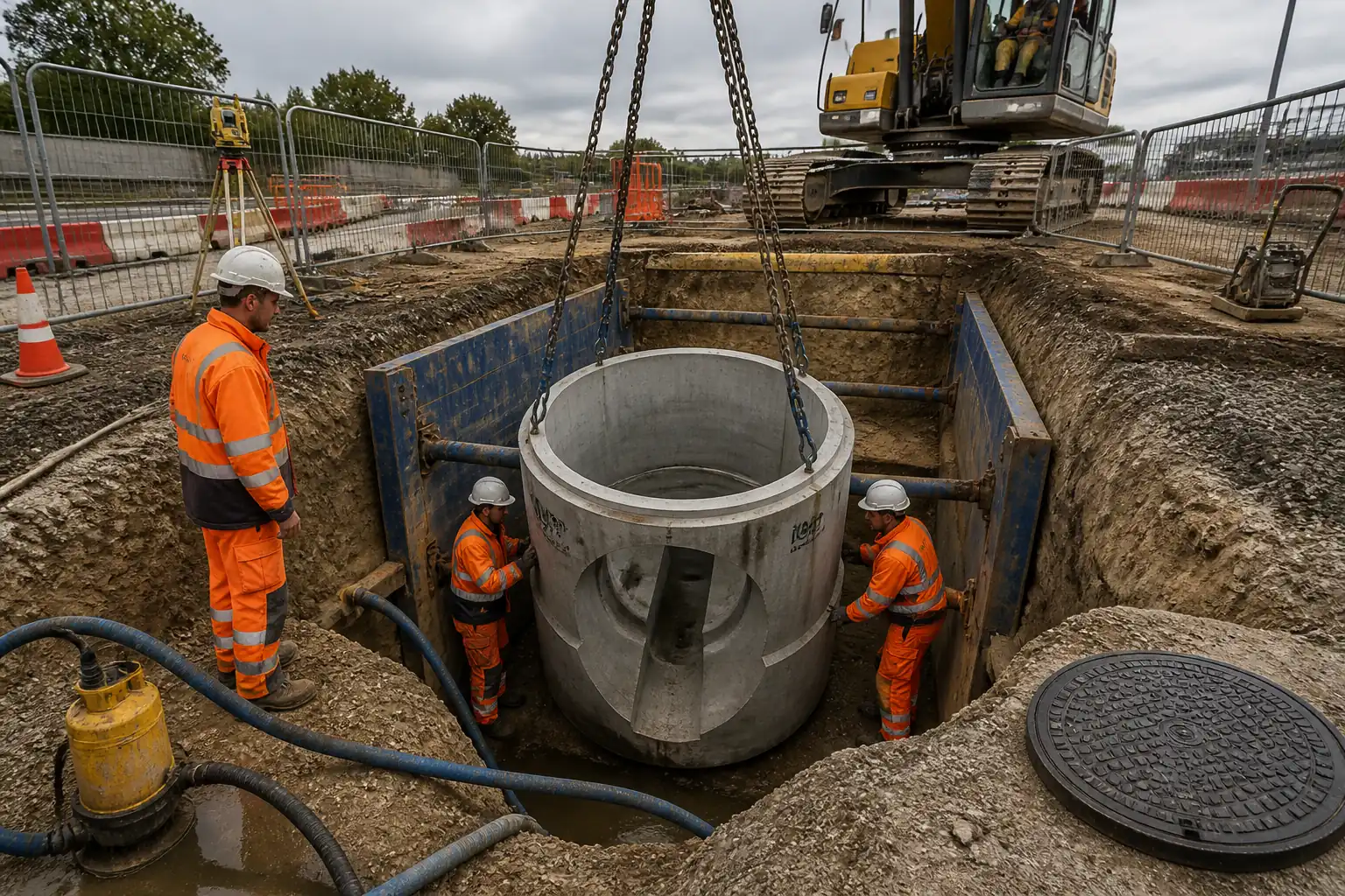
| Manhole connections | Visual, flexible connector fit | Watertight; correct alignment and rocker pipes | QA-QC / Engineer | IR, photos |
| Initial surround/sidefill | Placement/compaction observation | Uniform support; cover ≥150–300 mm above crown | QA-QC | Checklist |
| Backfill compaction (non-traffic) | Field density tests (ASTM D6938) | ≥95% MDD (ASTM D698) [Verify] | QA-QC / 3rd Party Lab | Density reports |
| Backfill compaction (traffic areas) | Field density tests (ASTM D6938) | ≥98% MDD (ASTM D1557) [Verify] | QA-QC / 3rd Party Lab | Density reports |
| Leakage test (air/water) | EN 1610 test procedure | Leakage/time limits per EN 1610 [Verify] | QA-QC / Specialist | Test certificates |
| Deflection test (flexible pipes) | Mandrel/deflectometer | ≤5% deflection [Verify] | QA-QC / Specialist | Test report |
| CCTV inspection | CCTV per WRC MSCC/PACP | No defects outside acceptance class; clear coding/report | Specialist / QA-QC | CCTV report/video |
| As-built survey | Survey verification | Coordinates/inverts within tolerance; drawings updated | Surveyor / QA-QC | As-built drawings/CSV |
This table is a read-only public reference. Download the PDF or Excel version, or customize this ITP to edit it for your project.
Frequently asked questions
Related method statement
This Inspection and Test Plan is associated with the Method Statement: Installation of Underground uPVC/HDPE Gravity Drainage Networks method statement, which describes the step-by-step construction sequence, resources, materials, equipment, safety controls, and environmental controls for this activity.
View the Method Statement: Installation of Underground uPVC/HDPE Gravity Drainage Networks method statement →Continue with related inspection, method statement, article, and checklist resources.