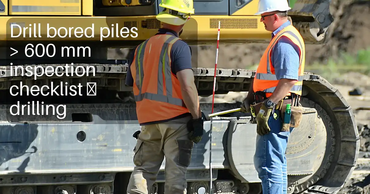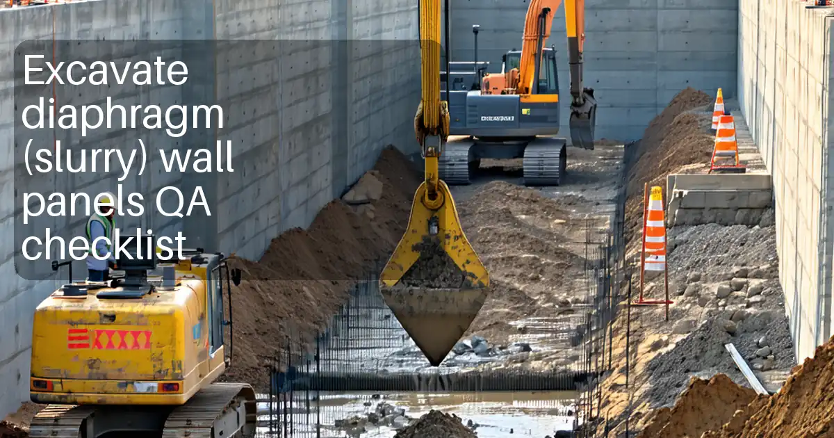
Excavate diaphragm (slurry) wall panels checklist for inspectors and supervisors focusing on slurry properties, trench verticality, and base cleanliness during excavation, excluding concreting, to ensure stable panels ready for acceptance.
- Control slurry density, viscosity, sand content, pH, and temperature.
- Verify trench verticality and alignment within tight survey tolerances.
- Confirm base cleanliness with sediment thickness and depth checks.
- Interactive, commentable checklist with export and QR code verification.
The checklist
Pre-Excavation Planning & Setup
- Confirm approved method statement, ITP, and permits are current; brief crew on hazards and hold points; record approvals and toolbox talk attendance with signatures and photos.
- Survey and set out panel limits and centerline; verify guide wall alignment and joint positions within ±25 mm of design; upload total-station report and marked photos.
- Check guide wall top level and straightness using digital level and taut string; tolerance: level within ±5 mm and face straight within ±5 mm; attach readings and images.
- Inspect and calibrate instruments: mud balance, Marsh funnel, sand content kit, pH meter, thermometer, weighted tape, inclinometer; verify certificates ≤6 months; upload certificates.
Slurry Preparation & Testing
- Mix bentonite or polymer slurry per supplier data; record batch ID, hydration time, and mixture proportions; photograph mixing plant and tank labels.
- Measure slurry density with mud balance before trench filling; acceptance: 1030–1120 kg/m³; log reading, temperature, time, and tester signature.
- Check Marsh funnel viscosity at 20 °C; acceptance: 32–50 s for fresh slurry; record seconds, temperature, and batch ID; upload timer photo.
- Test sand content of fresh slurry using a sand content kit; acceptance: ≤2% by volume; record percentage and photo of vial scale.
- Measure pH and temperature; acceptance: pH 8–11 and 10–30 °C; log readings and instrument serial numbers; attach meter screen photos.
Trench Excavation & Support
- Maintain slurry head during excavation at least 1.0 m above groundwater and 0.3–0.6 m below guide wall top; record level every 30 minutes with staff gauge photos.
- Excavate in controlled bites using grab/cutter; monitor trench width with calliper at guide walls; acceptance: overbreak ≤ +50 mm from design, no underwidth; upload readings.
- Sound depth with weighted tape after each bite; interim acceptance: reach target depth within +0.20 m; log depths at both ends and midspan with time-stamped photos.
- Continuously circulate slurry through desander during excavation; in-trench acceptance: sand content ≤4%; record flow rate, desander status, and sand content results.
- Monitor trench stability; if slurry level drops ≥0.5 m or loss observed, stop excavation, restore level, and notify engineer; document incident with photos and log entry.
Verticality & Alignment Control
- Verify grab alignment at start with guide frames/stop-end; acceptance: at panel top, centerline within ±25 mm; upload survey screenshot and annotated photo.
- Measure verticality using inclinometer or gyro tool at completion; acceptance: deviation ≤ 1:200 in both axes; attach raw data, plots, and instrument ID.
- Survey as-dug trench position at surface with total station; acceptance: trench centerline within ±25 mm of design; upload CSV and plan markup.
- Check stop-end or joint former plumb with spirit level/laser; acceptance: ≤ 1:200 and secure restraining; record measurements and fixings with photos.
Base Cleaning & Verification
- Clean trench base using clean-out bucket or air-lift pump until returns are clear; record cleaning method, duration, and photos of slurry returns.
- Measure base sediment thickness with weighted spoon/sonar at three locations; acceptance: ≤50 mm everywhere; log results and location sketch.
- Re-test in-trench slurry: density 1030–1150 kg/m³, Marsh 32–60 s, sand content ≤2%, pH 8–11; record readings with timestamps and photos.
- Confirm final depth with weighted tape at ends and midspan; acceptance: design depth achieved with overdepth ≤0.10 m; attach readings and video of bottom contact.
Documentation & Handover
- Compile excavation log: panel ID, dates, equipment, depths, slurry tests, surveys, incidents; attach photos/videos; sign by supervisor and QA inspector.
- Declare pre-concreting hold point; submit records for review per approved project specifications and authority requirements; upload engineer’s acceptance and generate QR-linked report.
Preview the printable checklist
Preview page one below. Open the image or download the PDF for all pages.

At a glance
- A field-proven sequence for slurry wall excavation that standardises slurry testing, trench monitoring, and base verification, reducing instability, inclusions, and misalignment while capturing evidence for compliant records and engineer acceptance.
- Acceptance cues are explicit: target density, viscosity, sand content, pH, verticality tolerance, alignment offsets, sediment thickness, and final depth. Each step specifies tools, frequency, and required documentation or photos.
- Interactive online checklist with tick, comment, and export features secured by QR code.
- Designed for bentonite or polymer slurry systems and adaptable to varied soil profiles, this checklist aligns with approved project specifications and authority requirements while staying strictly within the excavation scope (no concreting steps).
How to use this interactive excavation checklist
- Preparation: Gather calibrated Marsh funnel, mud balance, sand content kit, pH meter, thermometer, weighted tape, inclinometer, desander/air-lift, total station, radios, and full PPE.
- Open the checklist on your device, select project and panel ID, and brief the team on acceptance criteria and hold points.
- During work: Tick each item as completed, input readings (with units), attach photos/videos of instruments, survey screenshots, and slurry returns.
- Use comments to flag nonconformances, assign actions, and record corrective steps; mention responsible parties and deadlines.
- After completion: Review automatic summaries, ensure all mandatory evidence is attached, and verify tolerances are met.
- Export the commentable interactive checklist to PDF/Excel for the engineer; share the QR-secured link for record authentication.
- Sign-Off: Obtain digital signatures from supervisor, QA/QC, and the engineer; archive the final package in the project document system.
Control Slurry Properties to Stabilise the Trench
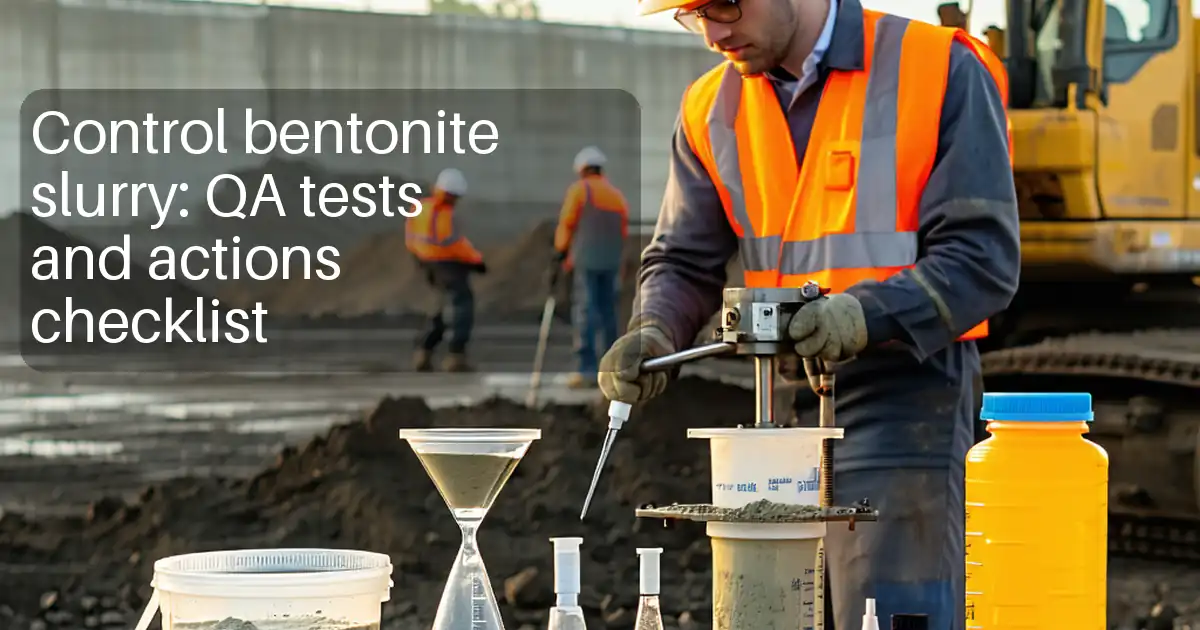
Slurry quality determines trench stability and base cleanliness during diaphragm wall excavation. Mix bentonite or polymer slurry in line with supplier data, then verify density, viscosity, sand content, pH, and temperature before introducing it into the panel. Maintain a positive hydrostatic head throughout excavation to counterbalance groundwater pressures. Continuous circulation through a desander limits sand buildup and promotes a thin, uniform filter cake. Record tests at defined intervals—typically at start, every 2 hours during excavation, and after base cleaning. Acceptable values commonly fall within 1030–1120 kg/m³ density and 32–50 s Marsh viscosity for fresh slurry, with sand content ≤2% fresh and ≤4% during excavation. On hot days, track temperature because viscosity shifts with heat. If results drift outside ranges, restore properties by dilution, rehydration, or replacing slurry. Consistent logging, with photos of instruments and returns, provides traceable evidence for acceptance and reduces instability and inclusion risks.
- Keep slurry head ≥1.0 m above groundwater at all times.
- Fresh slurry sand content ≤2%; in-trench during dig ≤4%.
- Record every test with time, temperature, and batch ID.
- Use desander circulation to manage sand load and clarity.
Verticality, Alignment, and Overbreak Control
Precise alignment starts at the guide walls and stop-ends. Survey centerline and joint positions, then verify the grab tracks within the guide using frames or templates. Measure verticality at the end of excavation using an inclinometer or gyro system; a typical acceptance is deviation ≤ 1:200 in both axes. At surface, confirm the as-dug trench centerline remains within ±25 mm of design to protect wall continuity and avoid loss of section. Overbreak is limited by careful bite sequencing and steady slurry head, with periodic checks on trench width near guide walls. If verticality exceeds tolerance, pause, assess soil conditions, and consult the engineer on mitigations such as bite reshaping or adjusted sequence on subsequent panels. Document all measurements and corrective actions. This controls rework risk and ensures panel-to-panel compatibility for joints and waterstops in the next phase.
- Survey centerline and joint positions before excavation.
- Verticality acceptance typically ≤ 1:200 both directions.
- As-dug centerline within ±25 mm of design.
- Limit overbreak to +50 mm from design width.
Base Cleaning and Acceptance Before Handover
Clean the trench base using an air-lift or a clean-out bucket until slurry returns indicate minimal fines. Then measure sediment thickness at multiple points using a weighted spoon or sonar; acceptance is ≤50 mm everywhere. Re-test slurry after cleaning to confirm density, viscosity, pH, and sand content meet in-trench limits, targeting ≤2% sand and stable density and viscosity ranges. Confirm final depth at three locations and document bottom contact to avoid false readings in soft formations. Photo and video evidence of clear returns, measurement tools touching bottom, and the log of readings help the engineer make quick decisions. Once acceptance criteria are met, declare the pre-concreting hold point and submit the compiled record set for review per approved project specifications and authority requirements.
- Sediment thickness ≤50 mm at all check points.
- Re-test slurry in-trench; sand content ≤2%.
- Verify final depth at ends and midspan.
- Submit records and secure pre-concreting hold point.