
Method Statement: Gravity Water Leak Testing for Sanitary Drainage Stacks and Underground Gravity Lines – Method Statement
AI-assisted method statement with matching ITP, PDF download, and Excel export.
More than a static template
Unlike a downloadable Word or PDF template, this method statement is an AI-assisted editable starting point connected directly to a matching Inspection and Test Plan. Every section is structured, project-adaptable, and ready to export.
- AI-assisted drafting — Customize every section with AI for your specific project scope.
- Linked ITP — A matching inspection and test plan is generated alongside the method statement.
- Multiple export formats — Download as a formatted PDF or editable Excel spreadsheet.
- Editable starting point, not a final document — Review, verify, and adjust all content against your project requirements before use.
Static template vs. Quollnet workflow
| Feature | Static template | Quollnet |
|---|---|---|
| Project-specific content | Manual fill-in required | AI-assisted customization |
| Linked ITP | Separate document, no link | Matching ITP included |
| Export formats | Usually PDF only | PDF and Excel |
| Structured sections | Free-form layout | 13 standardized sections |
| Saved to your account | Local file only | Cloud-saved, reusable |
| Content accuracy | You verify everything | AI-assisted, you still verify |
| Cost | Often free but time-intensive | Free to customize and download |
What you can customize
When you save this method statement to your account, every section becomes editable. The following 13 sections are included:
- Scope — Defines the activity and its boundaries.
- References — Standards, specifications, and drawings.
- Responsibilities — Roles and accountabilities.
- Resources — Labour, plant, and equipment summary.
- Materials — Materials and compliance requirements.
- Equipment — Tools and equipment details.
- Prerequisites — Hold points and pre-conditions.
- Method sequence — Step-by-step construction sequence.
- Safety controls — HSE risk controls and PPE.
- Environmental controls — Environmental mitigation measures.
- QA/QC — Quality inspection and test requirements.
- ITP — Inspection and Test Plan table (has its own page).
- Attachments — Referenced drawings and documentation.
Why this method statement is used
This method statement is used to define and communicate the approved procedure for carrying out method statement: gravity water leak testing for sanitary drainage stacks and underground gravity lines on site. It ensures the work is planned in advance, the correct resources and controls are in place, and all personnel understand responsibilities, sequence, quality requirements, and safety controls before work begins. It aligns site execution with the documented scope and acceptance expectations.
Who uses this method statement
This method statement is used by contractors, site supervisors, project engineers, QA/QC engineers, HSE officers, consultants, and client representatives. It serves as a shared reference for planning, execution, supervision, inspection, and approval of the activity on site.
When it is prepared and submitted
The method statement is prepared before the work activity starts and submitted as part of the pre-construction documentation package for review and approval.
Who reviews or approves it
The method statement is usually submitted to the client representative, consultant, resident engineer, or project management consultant for review and approval before the work commences.
Important approval note
This method statement is an AI-assisted editable starting point, not a pre-approved document. Before use on any project, all content must be reviewed and approved by the relevant parties (superintendent, principal contractor, or client representative) in accordance with your contract and project quality plan.
For example: if your specification requires a departure from a referenced standard, that departure must be documented and approved separately — this method statement will not capture that automatically. Always verify against your applicable drawings, specifications, and regulatory requirements.
Method statement content
Scope
Overview
This method covers gravity water leak testing of:
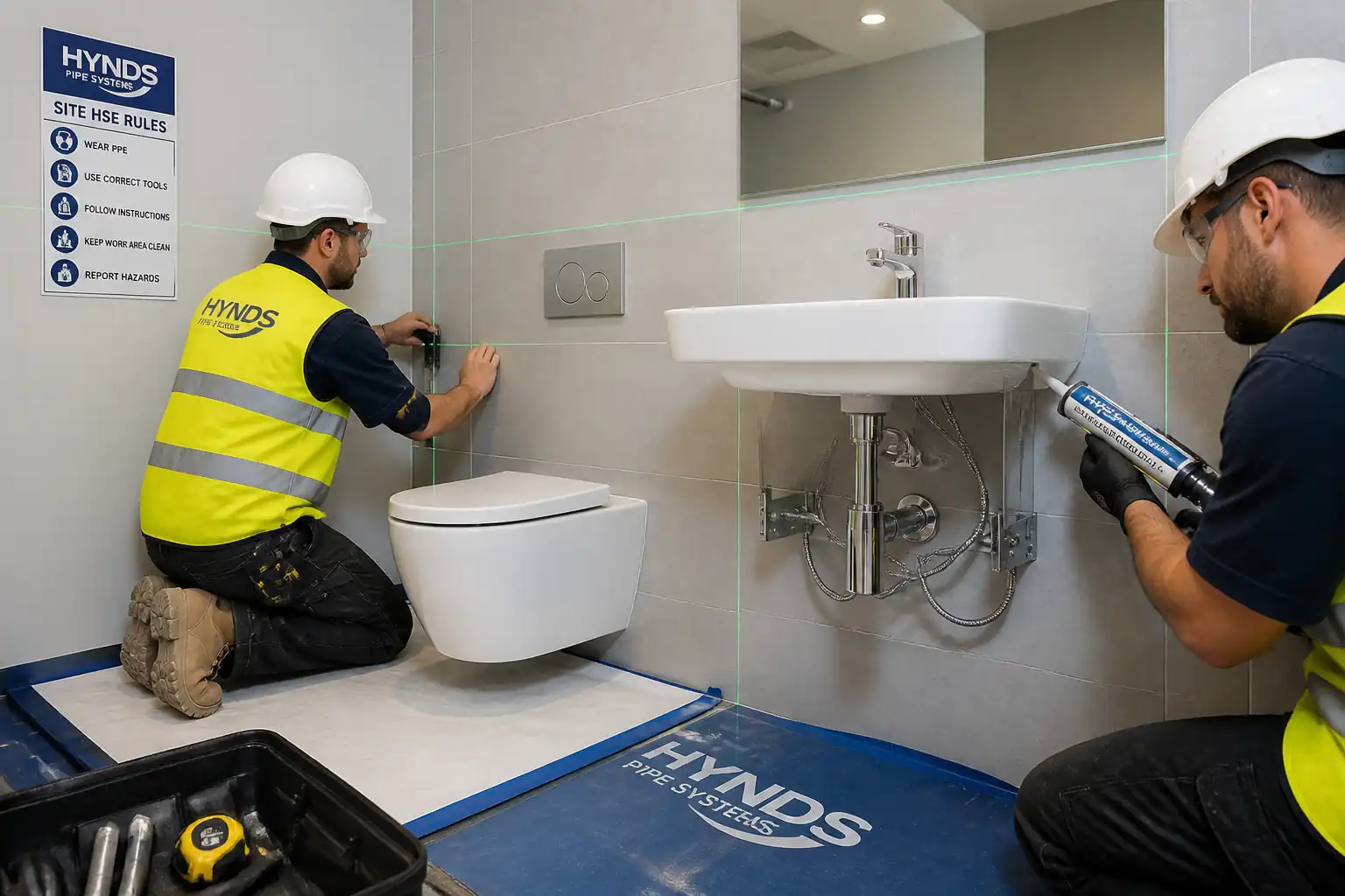
- Internal sanitary drainage stacks and connected branches by sectional or full-height water fill up to roof level or designated floor zones.
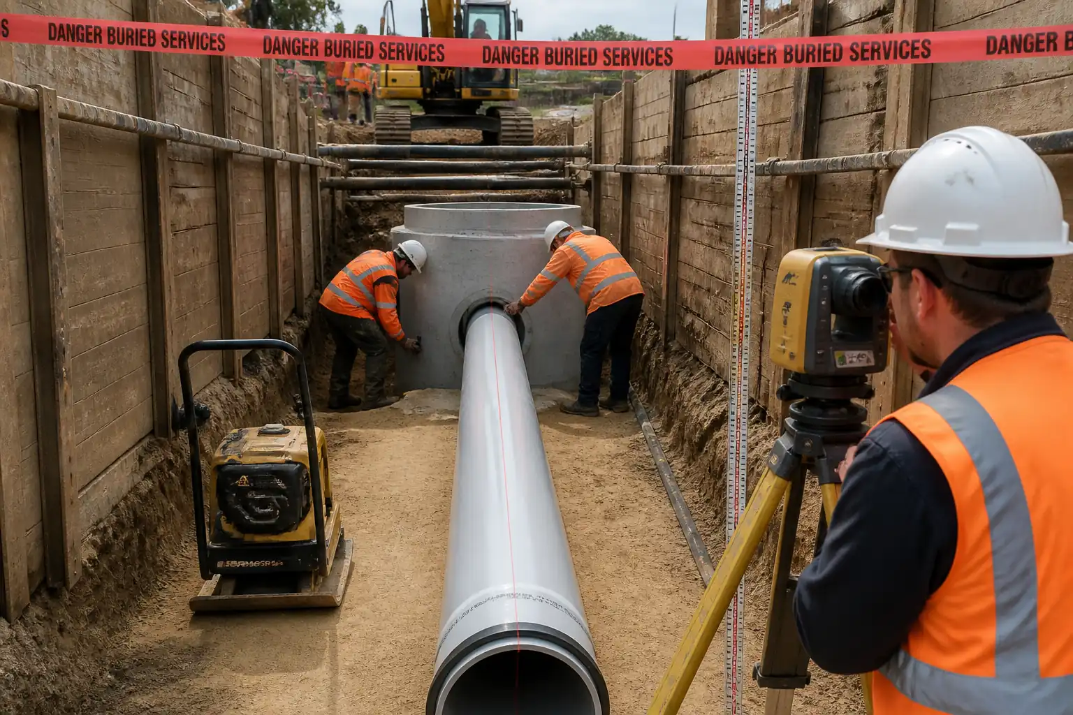
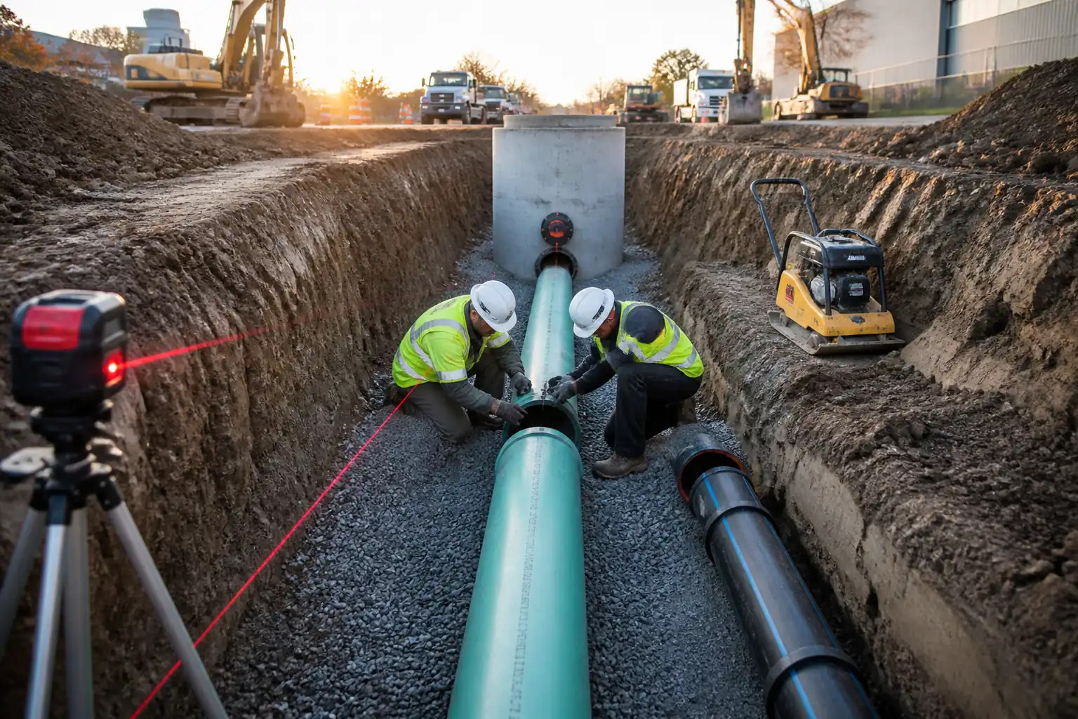
- Underground gravity drainage pipelines between manholes/inspection chambers.
Objectives
- Verify watertightness of pipes, fittings, and joints under static water head.
- Confirm no visible leakage and that water loss is within allowable limits or as per project specifications.
Extent
- All newly installed or modified sanitary drainage stacks, branches, and underground gravity lines prior to permanent concealment or backfilling and prior to handover.
Exclusions
- Low-pressure air testing methods (ASTM F1417) unless explicitly approved.
- Hydrostatic pressure testing of pressure mains (not gravity systems).
Key Acceptance Benchmarks [Verify per project specifications]
- Internal stacks: Minimum 3.0 m water head above highest fitting under test; initial 15 min no drop; 24-hour marked level drop within project-specified tolerance and no visible leaks.
- Underground lines: Water head typically 1.0–5.0 m above crown at highest point; stabilization 30–60 min; 30 min test with allowable loss within BS EN 1610 limits; no visible leakage.
References
| Document Type | Reference / Number | Revision | Notes |
|---|---|---|---|
| Standard | BS EN 12056-2 | Use for stack testing approach and definitions. | |
| Standard | BS EN 1610 | Defines head range, stabilization, and allowable water loss (project to confirm). | |
| Code | IPC 2021 | Use as benchmark where project specs are silent. [Verify with Authority Having Jurisdiction] | |
| Standard | ASTM C969 | Use only if required by project/authority. [Verify] | |
| Contract | Prevails over benchmarks in this method. | ||
| Standard | ISO 9001 / ISO 14001 | For system compliance. |
Responsibilities
| Role | Responsibility | Name / Party |
|---|---|---|
| PM | Approve method, program and resourcing. | Main Contractor |
| CM | Ensure workface readiness and supervision. | Main Contractor |
| Engineer | Define test heads, section lengths, and venting points. | Main Contractor |
| Foreman | Execute testing safely and accurately. | Main Contractor |
| QA/QC | Enforce acceptance criteria and traceability. | Main Contractor |
| HSE | Toolbox talks, inspections, and PTW. | Main Contractor |
| Surveyor | Provide test schematics. | Main Contractor |
| Lab/Agency | Issue compliance certificate. | Independent |
| Client Rep | Approve IRs and test certificates. | Client/Consultant |
Resources
| Resource Type | Description | Quantity | Remarks |
|---|---|---|---|
| Personnel | Lead test execution | 1 | |
| Personnel | Witness and records | 1 | |
| Personnel | Safety oversight | 1 | |
| Personnel | Install plugs, fill, monitor, drain | 3-6 | Per test front |
| Personnel | Control access around test areas | 1 |
Materials
| Material | Specification / Grade | Quantity | Remarks |
|---|---|---|---|
| Water | As required | Estimate 0.2–1.0 m³ per 10 m of DN100 stack [Verify] | |
| Dye | As needed | ||
| Lubricant | Small |
Equipment
| Equipment | Capacity / Type | Quantity | Inspection Required |
|---|---|---|---|
| Pipe test plugs | Set | ||
| Water bowser | 1–5 m³ | 1 | |
| Manometer | 1 per test | ||
| Measuring staff | 1 | ||
| Comms | As needed | ||
| WAH gear | As required | ||
| Wet vac | 20–50 L | 1–2 |
Prerequisites
Workface Readiness
- As-built verification completed for the test section; pipe sizes, materials, and routing confirmed.
- All branches within test section capped/plugged; vent points identified at high points; drains available at low points.
- All fixtures and appliances isolated or removed from the test section to avoid damage.
Permits and Notifications
- Permit-to-Work for water testing and Work at Height where applicable. [Verify per project HSE plan and local regulations]
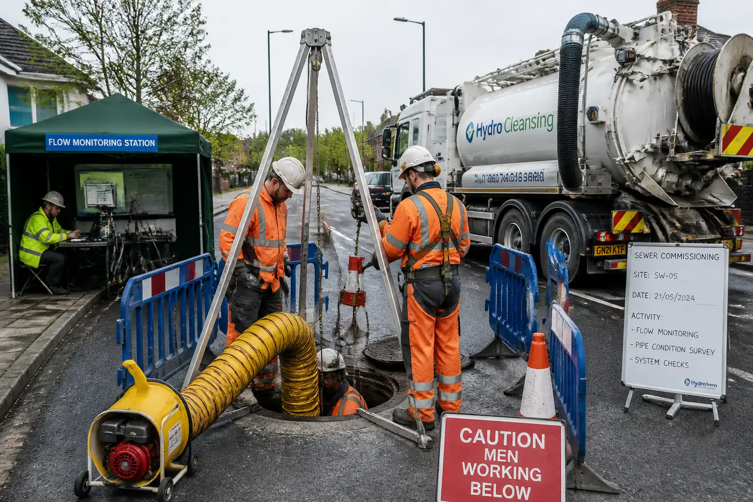
- Confined Space Entry permit for manholes/inspection chambers if entry is required.
- Advance notice to occupants/adjacent trades; signage and barriers erected.
Services Coordination
- Utility strike avoidance confirmed for any excavation access; underground lines located and manholes accessible.
- Coordination with structural/architectural teams to protect finishes during fills and drains; lay polythene sheeting in sensitive zones.
Instruments and Calibrations
- Manometers/pressure gauges calibrated within last 6 months; serial numbers recorded.
- Level datum boards installed and photographed before fill.
Water Management
- Confirm water source capacity and discharge route; prevent discharge to sensitive areas.
- Spill kits and wet vacs in place; drains downstream are open and capable of receiving test water.
Briefings
- Task-Specific Risk Assessment (TSRA) and Toolbox Talk conducted; roles and emergency plan briefed.
Weather and Thermal Considerations
- Record ambient and water temperatures at start and end for temperature-related level variations; apply corrections if specified by project.
Hold/Witness Points
- Notify Client/Consultant 24–48 hours before testing; arrange witness as per ITP.
Method Sequence
| Step | Activity | Description | Responsibility | Inspection / Hold Point |
|---|---|---|---|---|
| 1 | Pre-test inspection (stacks and underground) | Walk-down test section; verify plugs/blank-offs required; confirm vent and drain points; install level datum board. | MEP Site Engineer / QA/QC | ITP Hold/Witness |
| 2 | Install test plugs/end caps | Install mechanical or inflatable plugs at all outlets/branches and at base of stack or manhole interfaces; secure with safety tethers and secondary restraints where applicable; apply lubricant as needed. | Plumbing Crew | Supervisor check |
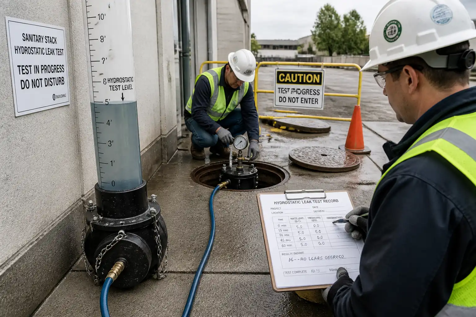
| 3 | Filling internal stacks (sectional or full-height) | Close lower isolation; fill slowly from lowest feasible point. Vent air at high points via vent pipe/standpipe. Target head: ≥3.0 m above highest fitting under test or to roof level as specified. Mark initial level on datum; record time and temperatures. | Plumbing Crew / Engineer | Witness |
| 4 | Initial tightness observation (stacks) | Maintain head for 15 minutes; conduct systematic visual inspection of all accessible joints and fittings along the tested section. | QA/QC / Engineer | Witness |
| 5 | 24-hour level drop tracking (stacks) | After initial acceptance, re-mark datum and secure area; re-check level after 24±2 hours; record ambient/water temperatures. | Engineer / QA/QC | Witness if required |
| 6 | Underground line preparation | Plug downstream manhole/outlet; ensure upstream access for filling; check trench/backfill stability; if unbackfilled, provide shoring/edge protection. | Plumbing Crew / HSE | Supervisor check |
| 7 | Filling underground pipelines | Fill slowly from upstream to achieve head of 1.0–5.0 m above crown at highest point or as specified; vent at high points; allow stabilization (30–60 min) to saturate pipe wall/liners. | Plumbing Crew / Engineer | Witness |
| 8 | Leak test of underground pipelines | Commence timed test (typically 30 min). Measure top-up volume required to maintain constant head using graduated cylinder/metered supply. | QA/QC / Engineer | Witness/Hold |
| 9 | Post-test draining and de-plugging | Controlled drain of water to approved discharge point; slowly release pressure before removing plugs; manage spill with trays/wet vac. | Plumbing Crew | Supervisor check |
| 10 | Rectification and re-test (if required) | Identify and repair leaks; allow curing time per manufacturer; repeat test sequence for affected sections. | Plumbing Crew / QA/QC | Witness |
| 11 | Documentation and sign-off | Compile results, calibration, photos, marked-up sketches, and approvals; submit Inspection Request (IR) for Client/Consultant sign-off. | QA/QC Engineer | Hold for approval |
Health, Safety, and Environment (HSE) – Safety Controls
Task-Specific Hazards and Controls
- Hazard: Plug failure/ejection due to hydrostatic head
- Likely consequence: Struck-by injury, flooding damage
- Engineering/procedural control: Use plugs rated ≥1.5× maximum test head; secure with safety chains/secondary restraint; fill slowly; do not stand in line of plug; depressurize before removal.
- Required PPE: Safety helmet with chin strap, face shield or safety goggles, gloves, safety boots.
- Collective preventive measure: Physical barriers and exclusion zones around plug locations; signage.
-
Inspection/permit/supervision: Supervisor to verify plug rating and installation; pre-use checklists; permit to test approved.
-
Hazard: Working at height (roof/upper floors for standpipes/vents)
- Likely consequence: Falls from height
- Engineering/procedural control: Use inspected scaffold/podium with guardrails; maintain three points of contact on ladders; avoid overreaching; tool lanyards.
- Required PPE: Fall-arrest where required, hard hat, non-slip footwear.
- Collective preventive measure: Edge protection and toe-boards; controlled access.
-
Inspection/permit/supervision: WAH permit/tag; daily scaffold inspection record; competent person supervision.
-
Hazard: Confined space entry to manholes/inspection chambers
- Likely consequence: Asphyxiation, toxic exposure, slips
- Engineering/procedural control: Confined Space Entry permit; gas test (O2, H2S, CO, LEL); forced ventilation; attendant and retrieval system.
- Required PPE: Tripod and harness, gas detector, gloves, boots, helmet, lighting.
- Collective preventive measure: Barriers around openings; rescue plan in place.
-
Inspection/permit/supervision: Authorized entrants only; permit and continuous monitoring. [Verify per project HSE plan and local regulations]
-
Hazard: Water discharge and flooding
- Likely consequence: Slip hazards, damage to finishes/services
- Engineering/procedural control: Predetermine discharge route; use hoses, trays, wet vacs; throttle valves; stop-fill emergency procedure.
- Required PPE: Waterproof gloves, boots.
- Collective preventive measure: Floor protection (polythene/absorbent mats); barriers and warning signs.
-
Inspection/permit/supervision: Supervisor approval of discharge plan.
-
Hazard: Manual handling of plugs, hoses, water containers
- Likely consequence: Musculoskeletal injury
- Engineering/procedural control: Team lifts; use trolleys; keep within safe lift limits; training.
- Required PPE: Gloves, safety boots.
- Collective preventive measure: Mechanical aids available.
-
Inspection/permit/supervision: Manual handling assessment completed.
-
Hazard: Interaction with other trades/public in occupied buildings
- Likely consequence: Trips, unauthorized tampering with test setups
- Engineering/procedural control: Lock-off/Tag-out of test valves; signage; cordon off floors; schedule off-hours where possible.
- Required PPE: Standard site PPE.
- Collective preventive measure: Access control and watchman.
-
Inspection/permit/supervision: Daily coordination meeting; permit to work.
-
Hazard: Noise and communication failure across floors
- Likely consequence: Mis-coordination causing overfill or spills
- Engineering/procedural control: Two-way radios; single appointed fill controller; pre-brief hand signals.
- Required PPE: Hearing protection if applicable.
- Collective preventive measure: Clear command-and-control protocol.
- Inspection/permit/supervision: Supervisor to control radios and sequence.
Environmental Controls
Controls for Water Use and Discharge
- Water consumption
- Control: Estimate volume per test; use metered supply; reuse test water where feasible; avoid continuous overflow.
-
Monitoring: Record volumes on test sheet.
-
Contaminated discharge risk (dye, debris)
- Control: Use non-toxic, non-staining dye only if approved; strainers on discharge; do not discharge to surface water drains unless approved.
-
Monitoring: Visual check of clarity; keep MSDS on site.
-
Ground/finish protection
- Control: Polythene sheeting and bunds under potential leak points; immediate cleanup of spills; wet vac on standby.
-
Monitoring: Housekeeping inspections during and after test.
-
Noise and disturbance in occupied facilities
- Control: Schedule during low-occupancy periods; notify stakeholders; keep pumps/valves throttled.
-
Monitoring: Supervisor walk-throughs; complaints log.
-
Waste management
- Control: Collect damaged plugs/consumables for proper disposal; segregate waste; no discharge of cementitious debris into drains.
-
Monitoring: Waste transfer notes as applicable.
-
Compliance
- Control: Follow project environmental plan and local discharge permits.
- Monitoring: HSE Officer verification. [Verify per project HSE plan and local regulations]
Quality Assurance and Quality Control (QA/QC)
QA/QC Approach
- 100% of new/modified stacks and underground lines to be water-tested prior to concealment/backfilling and handover unless waived in writing by the Client/Consultant.
- Measuring devices (manometers/pressure gauges) calibrated within 6 months; attach certificates to test package.
- Level readings recorded to nearest 5 mm with photo evidence at start and end of each reading window.
Acceptance Criteria [Verify per project specifications]
- Stacks/branches: Minimum 3.0 m head above highest fitting under test; 15-minute initial observation with zero visible leakage and no measurable drop; 24-hour level drop within project limit (typical benchmark 10–25 mm per 10 m stack length), no visible leakage.
- Underground lines: Head 1.0–5.0 m above crown at highest point; after stabilization 30–60 min, 30-minute test with allowable water loss not exceeding limits defined by BS EN 1610 for the specific diameter/material and test configuration; no visible leakage.
Temperature Considerations
- Record ambient and water temperatures at the start and end of each test. Where specified by project, apply temperature correction using approved tables or method statement appendix. If not specified, evaluate results with engineering judgement and visible leak evidence; seek Consultant direction.
Documentation
- Pre-test checklist, plug certificates, calibration certificates, annotated test sketches, photos of datum/levels, daily logs, and signed Inspection Requests (IRs)/Test Certificates.
- Nonconformity and Corrective Action records for any failed sections; retest documentation after repair.
Hold/Witness Points
- As defined in the ITP: Pre-test setup (Hold), Initial observation (Witness), Underground pipeline test (Hold), Final acceptance (Hold).
Attachments
Included/Referenced Attachments
- Test sketches showing sections, head measurement points, vent/drain locations, and plug positions.
- Calibration certificates for gauges/manometers (within 6 months).
- Manufacturer data sheets and rating certificates for test plugs/end caps.
- Sample test sheets/logs for stacks and underground pipelines.
- Toolbox talk (TBT) register and Task-Specific Risk Assessment (TSRA).
- Permit-to-Work copies (Work at Height, Confined Space) where applicable.
- Photos of datum boards/level marks at start and end of tests.
- Nonconformance and Corrective Action forms (if any) and retest records.
Note: Where project-specific acceptance parameters differ, attach the approved project specification excerpt and highlight any deviations.
This content is a read-only public reference. Download or customize to get an editable version.
ITP preview
The first inspection activities from the linked ITP for Method Statement: Gravity Water Leak Testing for Sanitary Drainage Stacks and Underground Gravity Lines:
| Activity | Inspection / Test | Acceptance Criteria | Responsibility | Record |
|---|---|---|---|---|
| Pre-test readiness inspection | Checklist: plugs available, vents/drains identified, access/permits in place, instrumentation calibrated | All prerequisites met; drawings/sections confirmed; datum installed and photographed | MEP Site Engineer / QA/QC / HSE | Pre-test readiness checklist, photos, PTW/permits copies |
| Plug installation verification | Visual check of size, rating, seating, and safety tethers | Plugs rated ≥1.5× max test head; correctly installed and secured; no damage to pipework | QA/QC Engineer | Plug log with serial numbers/certificates |
| Stack filling and stabilization | Head measurement at standpipe/manometer; air bleed confirmation | Head ≥3.0 m above highest fitting under test or per spec; stable level after 10–15 min | Engineer / QA/QC | Fill log; head readings; photos of datum |
Showing 3 of 9 inspection activities. View full ITP →
Related Inspection and Test Plan
An Inspection and Test Plan (ITP) is available for Method Statement: Gravity Water Leak Testing for Sanitary Drainage Stacks and Underground Gravity Lines. The ITP defines the inspection activities, acceptance criteria, hold and witness points, responsible parties, and records required to verify the work described in this method statement.
View the Method Statement: Gravity Water Leak Testing for Sanitary Drainage Stacks and Underground Gravity Lines ITP →Frequently asked questions
Continue with related Quollnet resources connected to this method statement.