
Inspection and Test Plan for Method Statement: Gravity Water Leak Testing for Sanitary Drainage Stacks and Underground Gravity Lines
AI-assisted inspection and test plan connected to a method statement, with PDF and Excel export.
More than a static template
Unlike a downloadable Word or PDF template, this ITP is an AI-assisted editable starting point directly connected to its method statement. Every inspection activity, hold point, and acceptance criterion is structured and ready to adapt to your project.
- AI-assisted customization — Tailor inspection activities and acceptance criteria to your specific project scope.
- Linked method statement — This ITP is connected to the corresponding method statement describing the work sequence.
- Multiple export formats — Download as a formatted PDF or editable Excel spreadsheet.
- Editable starting point, not a final document — Review and verify all content against your project specifications and standards before use.
What you can customize
When you save this ITP to your account, every inspection row becomes editable. You can add, remove, or modify:
- Inspection activity — Description of what is being inspected.
- Inspection type — Hold point (H), Witness point (W), Review (R), or Monitor (M).
- Responsibility — Contractor, subcontractor, engineer, or client.
- Frequency — How often the inspection occurs.
- Acceptance criteria — Referenced standard or specification requirement.
- Records — Forms, test reports, or checklists required as evidence.
Why this ITP is used
To verify watertightness and compliance before concealment or handover, preventing leaks and subsequent damage.
Who uses this inspection and test plan
MEP engineers, QA/QC personnel, HSE officers, plumbing crews, and Client/Consultant representatives.
When this ITP is prepared and submitted
After installation and cleaning of the drainage system, before concealment/backfilling and commissioning.
Who receives or approves this ITP
Client/Consultant for review and approval before works and for final acceptance.
Inspection scope
Pre-test readiness, plug installation, controlled filling, stabilization, timed leak measurements, 24-hour monitoring for stacks, documentation.
Typical hold, witness, and review points
Hold: Pre-test setup, underground timed test, final acceptance. Witness: Stack fill and initial 15-min check, 24-hour reading.
Typical inspection records
Pre-test checklist, calibration certificates, plug certificates, head readings, top-up volumes, photos, IR/Test certificates.
Important approval note
This ITP is an AI-assisted editable starting point, not a pre-approved document. Before use on any project, all inspection activities, hold points, and acceptance criteria must be reviewed and approved by the relevant parties (superintendent, principal contractor, or client representative) in accordance with your contract and project quality plan.
Always verify acceptance criteria against your applicable drawings, specifications, and regulatory requirements. Hold points must be confirmed with the relevant authority before work proceeds past that point.
Inspection and test plan
| Activity | Inspection / Test | Acceptance Criteria | Responsibility | Record |
|---|---|---|---|---|
| Pre-test readiness inspection | Checklist: plugs available, vents/drains identified, access/permits in place, instrumentation calibrated | All prerequisites met; drawings/sections confirmed; datum installed and photographed | MEP Site Engineer / QA/QC / HSE | Pre-test readiness checklist, photos, PTW/permits copies |
| Plug installation verification | Visual check of size, rating, seating, and safety tethers | Plugs rated ≥1.5× max test head; correctly installed and secured; no damage to pipework | QA/QC Engineer | Plug log with serial numbers/certificates |
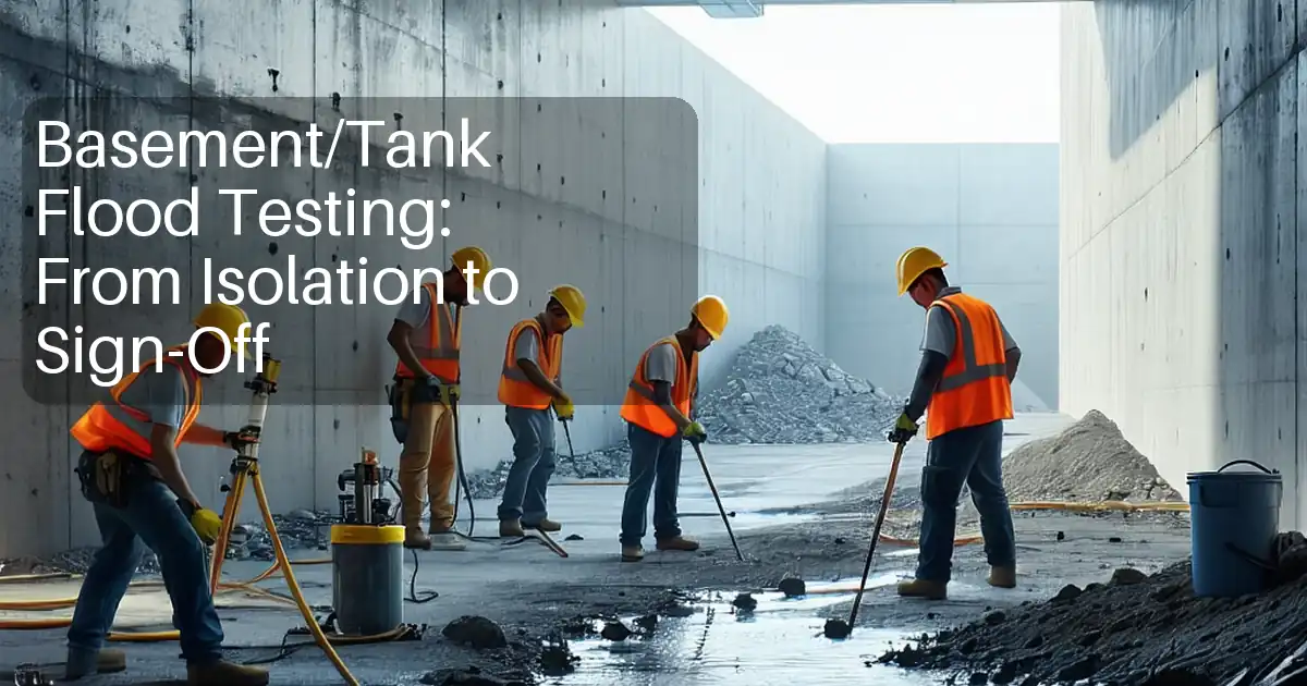
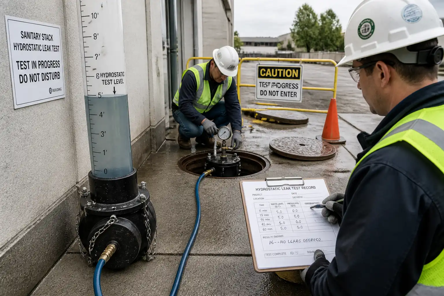
| Stack filling and stabilization | Head measurement at standpipe/manometer; air bleed confirmation | Head ≥3.0 m above highest fitting under test or per spec; stable level after 10–15 min | Engineer / QA/QC | Fill log; head readings; photos of datum |
| Stack initial tightness check (15 min) | Visual joint inspection and level observation | No visible leakage; no measurable level drop in 15 min or within project-specified tolerance [Verify] | QA/QC / Client Rep (Witness) | Inspection sheet; photo/video evidence |
| Stack 24-hour level drop monitoring | Re-read marked level after 24±2 hours; record temperatures | No visible leakage; total drop within project limit (typ. 10–25 mm/24 h per 10 m stack) [Verify] | Engineer / QA/QC | 24 h log; photos of initial/final levels; temperature log |
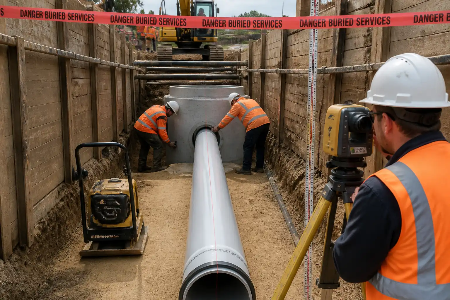
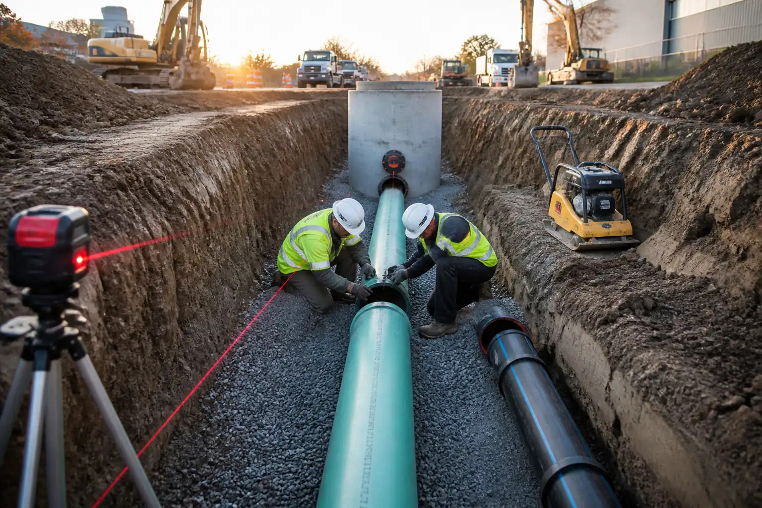
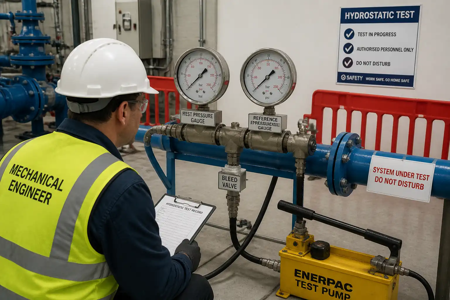
| Underground pipeline hydrostatic test setup | Verify downstream plug position; confirm head measurement reference; stabilization time recorded | Head target 1.0–5.0 m above crown at highest point; safe setup ready | Engineer / QA/QC / HSE | Setup checklist; photos; head calc sheet |
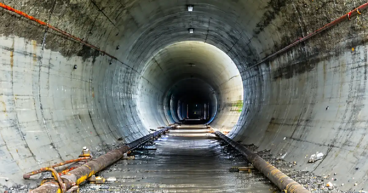
| Underground pipeline hydrostatic test (timed) | Top-up volume to maintain constant head over 30 min | Water loss within BS EN 1610 allowable limits for pipe/chamber; no visible leakage | QA/QC / Client Rep (Hold) | Test sheet with volumes, calculations, duration; photos |
| Drain-down and reinstatement | Controlled discharge; area inspection | No uncontrolled spills; area clean; system left in safe state | Plumbing Foreman / Engineer | Drain log; housekeeping checklist |
| Final documentation and acceptance | Review of complete records against ITP | All records complete; nonconformities closed; IR/Test certificate signed | QA/QC / Client Rep | Signed IR; Test Certificate; compiled dossier |
This table is a read-only public reference. Download the PDF or Excel version, or customize this ITP to edit it for your project.
Frequently asked questions
Related method statement
This Inspection and Test Plan is associated with the Method Statement: Gravity Water Leak Testing for Sanitary Drainage Stacks and Underground Gravity Lines method statement, which describes the step-by-step construction sequence, resources, materials, equipment, safety controls, and environmental controls for this activity.
View the Method Statement: Gravity Water Leak Testing for Sanitary Drainage Stacks and Underground Gravity Lines method statement →Continue with related inspection, method statement, article, and checklist resources.