
Method Statement: Pre-Commissioning and Final Flow Testing of Sewerage Network – Method Statement
AI-assisted method statement with matching ITP, PDF download, and Excel export.
More than a static template
Unlike a downloadable Word or PDF template, this method statement is an AI-assisted editable starting point connected directly to a matching Inspection and Test Plan. Every section is structured, project-adaptable, and ready to export.
- AI-assisted drafting — Customize every section with AI for your specific project scope.
- Linked ITP — A matching inspection and test plan is generated alongside the method statement.
- Multiple export formats — Download as a formatted PDF or editable Excel spreadsheet.
- Editable starting point, not a final document — Review, verify, and adjust all content against your project requirements before use.
Static template vs. Quollnet workflow
| Feature | Static template | Quollnet |
|---|---|---|
| Project-specific content | Manual fill-in required | AI-assisted customization |
| Linked ITP | Separate document, no link | Matching ITP included |
| Export formats | Usually PDF only | PDF and Excel |
| Structured sections | Free-form layout | 13 standardized sections |
| Saved to your account | Local file only | Cloud-saved, reusable |
| Content accuracy | You verify everything | AI-assisted, you still verify |
| Cost | Often free but time-intensive | Free to customize and download |
What you can customize
When you save this method statement to your account, every section becomes editable. The following 13 sections are included:
- Scope — Defines the activity and its boundaries.
- References — Standards, specifications, and drawings.
- Responsibilities — Roles and accountabilities.
- Resources — Labour, plant, and equipment summary.
- Materials — Materials and compliance requirements.
- Equipment — Tools and equipment details.
- Prerequisites — Hold points and pre-conditions.
- Method sequence — Step-by-step construction sequence.
- Safety controls — HSE risk controls and PPE.
- Environmental controls — Environmental mitigation measures.
- QA/QC — Quality inspection and test requirements.
- ITP — Inspection and Test Plan table (has its own page).
- Attachments — Referenced drawings and documentation.
Why this method statement is used
This method statement is used to define and communicate the approved procedure for carrying out method statement: pre-commissioning and final flow testing of sewerage network on site. It ensures the work is planned in advance, the correct resources and controls are in place, and all personnel understand responsibilities, sequence, quality requirements, and safety controls before work begins. It aligns site execution with the documented scope and acceptance expectations.
Who uses this method statement
This method statement is used by contractors, site supervisors, project engineers, QA/QC engineers, HSE officers, consultants, and client representatives. It serves as a shared reference for planning, execution, supervision, inspection, and approval of the activity on site.
When it is prepared and submitted
The method statement is prepared before the work activity starts and submitted as part of the pre-construction documentation package for review and approval.
Who reviews or approves it
The method statement is usually submitted to the client representative, consultant, resident engineer, or project management consultant for review and approval before the work commences.
Important approval note
This method statement is an AI-assisted editable starting point, not a pre-approved document. Before use on any project, all content must be reviewed and approved by the relevant parties (superintendent, principal contractor, or client representative) in accordance with your contract and project quality plan.
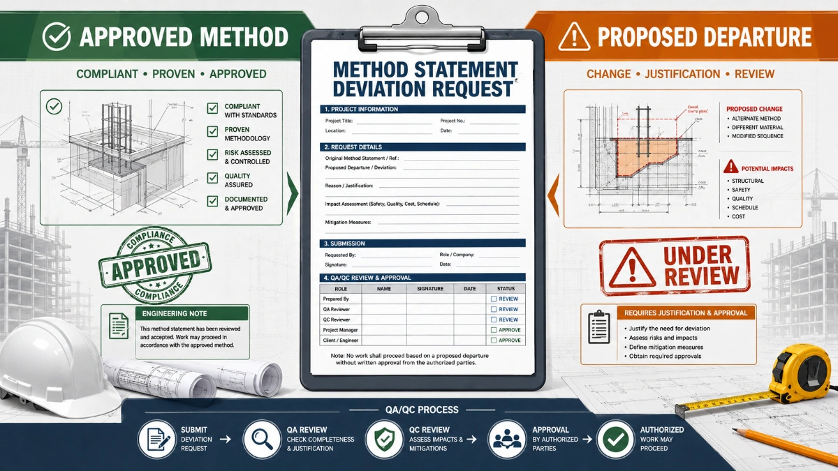
For example: if your specification requires a departure from a referenced standard, that departure must be documented and approved separately — this method statement will not capture that automatically. Always verify against your applicable drawings, specifications, and regulatory requirements.
Method statement content
Scope
Overview
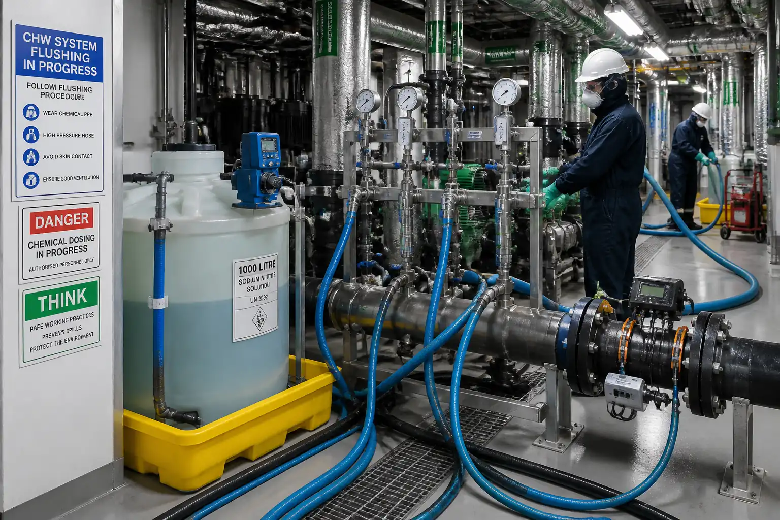
This method statement covers pre-commissioning and final flow testing of the complete gravity sewerage network, including manholes, laterals, and trunk mains, from the most upstream terminal points to the designated discharge point or connection to the existing system. Activities include pre-start coordination, debris clearance (jetting/rodding), controlled removal of temporary plugs, high-velocity water flushing, dye tracing (as required), hydraulic performance verification (depth/velocity and transit time), optional leakage verification where specified, final CCTV survey, reinstatement, and compilation of handover documentation.
Objectives
- Demonstrate the sewer network is free from debris, obstructions, and construction residues.
- Verify hydraulic performance against design intent (self-cleansing velocity, depth profiles, no surcharge under test conditions, no ponding/sags beyond acceptable limits).
- Confirm correct connectivity and flow direction, including laterals, using dye tracing where applicable.
- Confirm manhole integrity, benching, and covers are compliant.
- Provide complete QA/QC records and obtain Engineer/Authority acceptance.
Limitations
- This method applies to gravity conduits; pressure mains are excluded.
- Leakage testing is executed only where specified by the Project Specifications or Authority requirements [Verify per project specifications].
- Discharge, water abstraction, and road space occupancy are subject to permits [Verify per project HSE plan and local regulations].
Interfaces
- Coordination with Roadworks/Traffic Management, Utility Owners (water source and discharge consent), Operations (WWTP/receiving system), and adjacent contractors for tie-ins and overpumping (if required).
References
| Document Type | Reference / Number | Revision | Notes |
|---|---|---|---|
| Standard | BS EN 752 | ||
| Standard | BS EN 1610 | Leakage test parameters to be verified per project/authority | |
| Standard | BS EN 13508-2 | Use compatible defect coding schema | |
| Standard/Guideline | ISO 6416 / ISO 748 (as applicable) | For area-velocity and calibration good practice [Verify applicability] | |
| Standard | ISO 5667 series | Sampling protocols where consent conditions apply | |
| Standard | BS EN 1717 | Specify BA-type backflow prevention [Verify per water authority] | |
| Project Documents | Governing values to be verified per project |
Responsibilities
| Role | Responsibility | Name / Party |
|---|---|---|
| Construction Manager | Overall execution, sequencing, coordination with stakeholders, and resources | Contractor |
| QA/QC Engineer | Method compliance, ITP implementation, hold/witness coordination, NCR management | Contractor |
| Site Engineer | Site supervision, permits-to-work, daily briefings, interface with traffic management | Contractor |
| HSE Officer | Confined space entry control, gas monitoring, rescue readiness | Contractor |
| Jetting Operator | Operate jetting/vacuum unit and ensure cleaning quality | Specialist Subcontractor |
| CCTV Operator | CCTV inspection, reporting to BS EN 13508-2 | Specialist Subcontractor |
| Flow Testing Engineer | Flow measurement, dye tracing, data logging, preliminary analysis | Contractor/Specialist |
| Engineer/Authority Representative | Review/approve hold points, witness key tests, sign acceptance | Engineer/Client |
Resources
| Resource Type | Description | Quantity | Remarks |
|---|---|---|---|
| Personnel | 1 | ||
| Personnel | 1–2 | ||
| Personnel | 1 | ||
| Personnel | 2 (operator + assistant) | ||
| Personnel | As per TMP | ||
| Personnel | 3–4 |
Materials
| Material | Specification / Grade | Quantity | Remarks |
|---|---|---|---|
| Flushing Water | Free of debris, approved source with backflow prevention | As calculated (≥3 pipe volumes per reach) [Verify] | |
| Dye Tracer | Non-toxic; SDS available | As required | |
| Temporary Plugs/Packers | Sized to pipe DN, rated for 10–50 kPa | Assorted | |
| Silt/Sediment Control Media | For protecting receiving drains | Sufficient stock | |
| Spill Kits & Absorbents | Hydrocarbon compatible | Kits per work zone |
Equipment
| Equipment | Capacity / Type | Quantity | Inspection Required |
|---|---|---|---|
| Jet-Vac Truck | Flow 200–400 L/min @ 100–150 bar | 1–2 | Pre-use check, certification |
| Water Supply Assembly | 1 | Calibration/authority approval | |
| Flow Meters (AV) | 2+ | Calibration certs | |
| CCTV Inspection System | 1 set | Function test | |
| Multi-Gas Detectors (4/5 Gas) | 2–4 | Calibration/bump test logs | |
| Ventilation Blowers | 2 | PAT/inspection | |
| Confined Space Rescue Kit | 1 set | Inspection before use | |
| Inflatable Pipe Plugs & Controllers | As required | Pressure/leak check | |
| Traffic Management Kit | As per TMP | Daily inspection |
Prerequisites
- Approved Method Statement and ITP issued and briefed to all personnel (toolbox talk).
- Permits: Confined Space Entry (CSE), Road Opening/Traffic Management, Water Abstraction, Discharge Consent, Hot Works (if any), and Work at Night (if applicable) [Verify per project HSE plan and local regulations].
- Issued-for-Construction drawings, latest design hydraulic parameters (design flows, slopes), and approved as-built survey for installed lines.
- Confirmation of downstream system availability (WWTP/receiving manhole) or approved overpumping/bypass arrangement.
- Temporary works verified: plugs, overpumping, flow diversion, and safe access/egress to manholes.
- All utilities and connections identified; lateral status list (permanent open vs. capped) available.
- Calibration certificates for flow meters, water meters, gas detectors, pressure gauges; equipment pre-use inspections completed.
- Weather assessment: avoid heavy rainfall events that may invalidate hydraulic tests; implement contingency plan.
- Environmental controls prepared: silt socks/booms, spill kits, containment plan, sampling kits if required by discharge consent.
- Emergency response plan for H2S exposure, drowning/asphyxiation, uncontrolled release, traffic incident; rescue team and equipment on standby.
- Stakeholder notifications issued: local authority, road users (where required), asset owner/Operator; test schedule circulated.
- Backflow prevention device installed and verified for any connection to potable water source per BS EN 1717.
Method Sequence
| Step | Activity | Description | Responsibility | Inspection / Hold Point |
|---|---|---|---|---|
| 1 | Pre-start coordination and permits | Verify all permits (CSE, TMP, abstraction/discharge) and approvals are active for the day; conduct task-specific briefing. | Site Engineer / HSE Officer | Permit check |
| 2 | Site establishment and traffic management | Install barriers, signs, cones, lamps as per approved TMP; delineate exclusion zones around manholes and jetting unit. | Traffic Marshals | TMP compliance inspection |
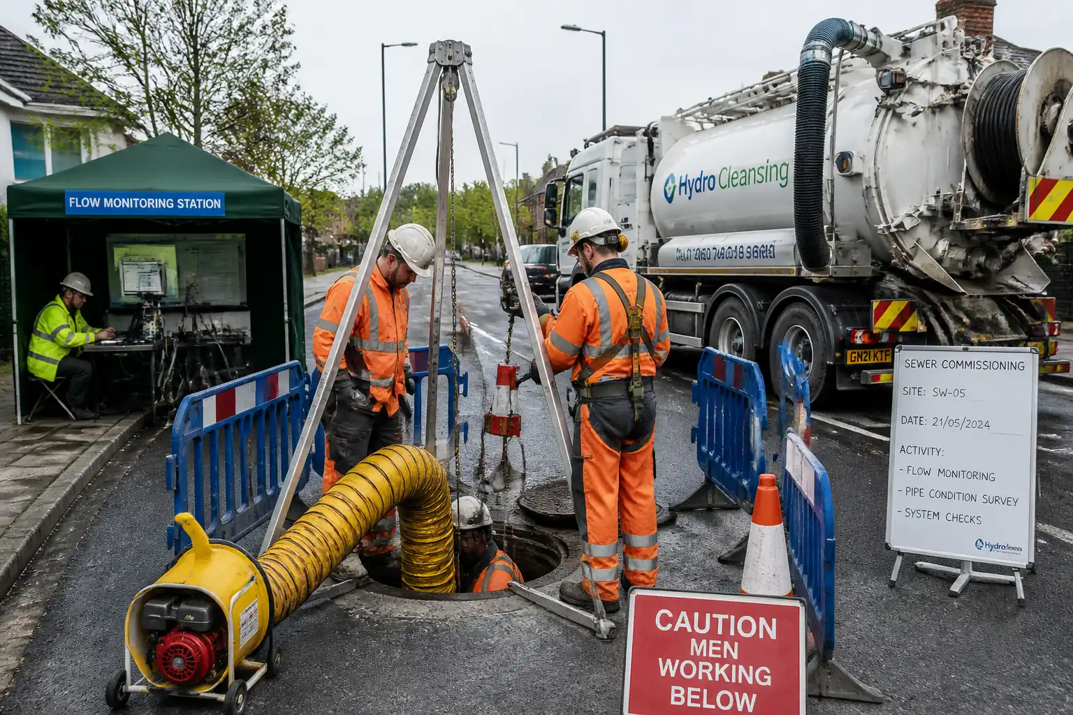
| 3 | Confined space preparation | Test atmosphere at access cover before opening; set up tripod, retrieval, ventilation; continuous gas monitoring during entry. | CSE Supervisor | Gas readings; equipment check |
| 4 | Initial manhole and line inspection | Open downstream manhole; visual inspect benching, steps, channel; confirm downstream path is free; verify plugs/packers in place upstream. | Site Engineer | Visual inspection |
| 5 | Controlled removal/adjustment of temporary plugs | Starting at downstream reach, slowly depressurize and remove temporary plugs as per sequence to prevent uncontrolled release; retain upstream isolation until jetting flush path is prepared. | Site Engineer / Specialist | Pressure gauge check; control line functional |
| 6 | Debris clearance – jetting and vacuuming | Jet from upstream to downstream using appropriate nozzle; retrieve debris at downstream manhole with vacuum. Typical jetting pressure 100–150 bar, flow 200–300 L/min [Verify per pipe material]. Avoid damage to linings and laterals. | Jetting Operator | Nozzle selection; pressure logged |
| 7 | Interim CCTV survey (post-clean) | CCTV inspect cleaned reaches to BS EN 13508-2; confirm no significant defects/obstructions before flushing. | CCTV Operator | Video review by QA/QC |
| 8 | Water source setup with backflow prevention | Connect hydrant standpipe with approved backflow preventer and inline water meter; verify capacity to achieve target velocity. | Site Engineer | Authority approval; meter reading |
| 9 | High-velocity flushing | Introduce water from upstream to achieve target velocity Vt = 1.0–1.5 m/s [Verify]. Maintain Vt for min 2–5 minutes or ≥ 3 pipe volumes per reach (whichever greater). Control discharge at downstream with silt/screening. | Jetting/Flushing Crew | Flowrate vs. meter; time |
| 10 | Dye tracing (if required) | Dose non-toxic dye at upstream MH; observe at downstream MH. Record transit time; repeat for key laterals to confirm connectivity and direction. | Flow Testing Engineer | Observation; timing |
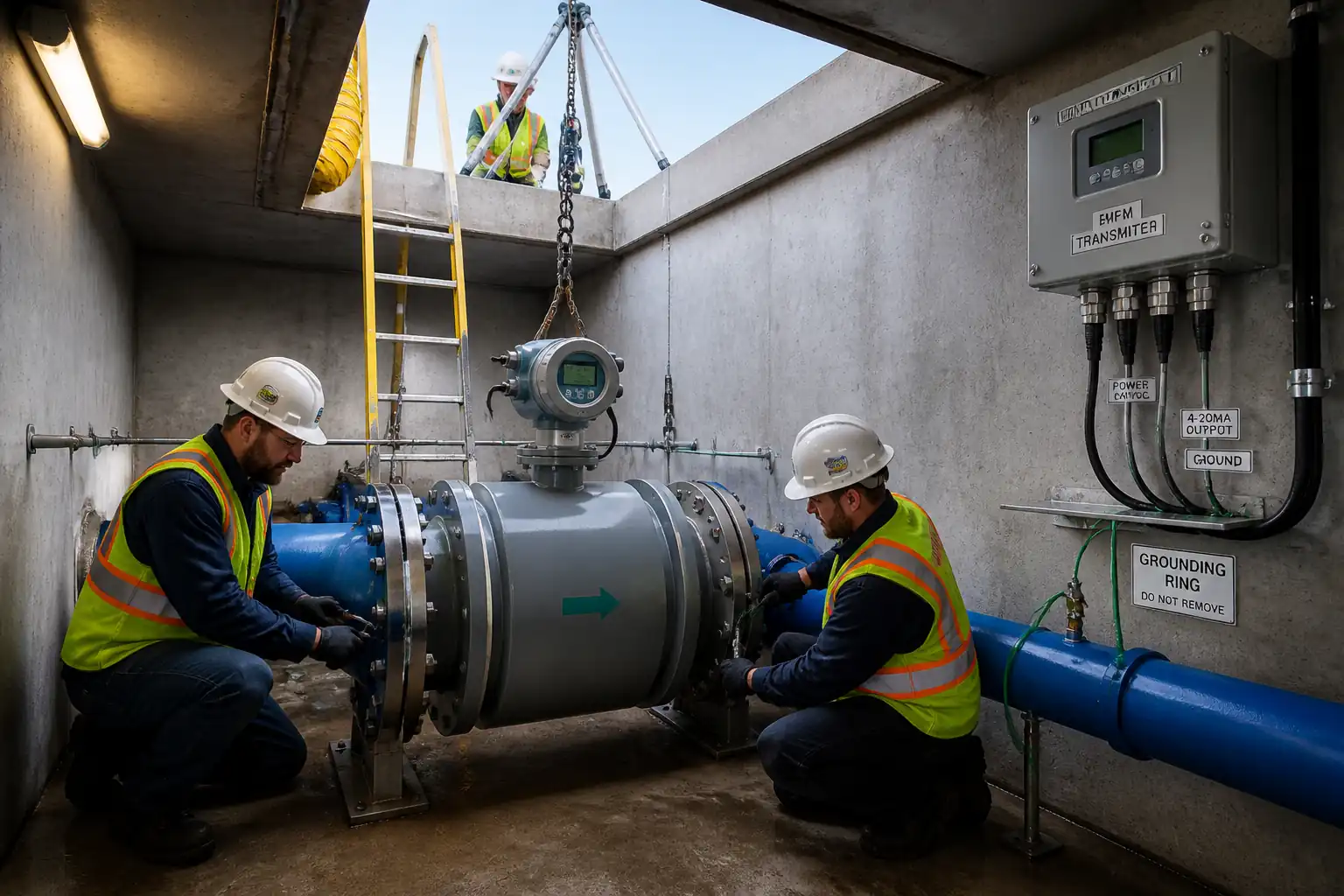
| 11 | Hydraulic performance verification | Install area–velocity meter in test reach; introduce steady inflow (from hydrant or controlled upstream head). Record depth (y) and velocity (v) over ≥10-min stable period. | Flow Testing Engineer | Instrument calibration; data quality check |
| 12 | Drain-down and ponding check | Cease inflow; observe recession. Check for standing water. Verify invert continuity with CCTV/laser as specified. | Site Engineer / CCTV Operator | Visual/CCTV |
| 13 | Optional leakage verification (if specified) | Conduct water infiltration/exfiltration test per BS EN 1610: apply test head 10–50 kPa at crown; stabilize; measure loss over test duration. | QA/QC Engineer | Gauge verification; head measurement |
| 14 | Final CCTV survey | CCTV entire network post-testing; confirm cleanliness and condition; update defect register. | CCTV Operator | Report review |
| 15 | Waste management and reinstatement | Dispose of collected debris/sludge at licensed facility; remove TMP; reinstate covers, frames, and surfaces. | Construction Manager | Waste consignment; reinstatement inspection |
| 16 | Handover documentation | Compile and submit test certificates, logs, calibration records, CCTV reports, as-builts, redlines, and acceptance forms; hold close-out meeting. | QA/QC Engineer | Document review |
Health, Safety, and Environment (HSE) – Safety Controls
Task-specific hazards and controls
- Hazard: Confined space entry (oxygen deficiency, H2S, methane)
- Likely consequence: Asphyxiation, poisoning, explosion
- Engineering/procedural control: CSE permit; continuous multi-gas monitoring; forced ventilation; intrinsically safe equipment; limit occupancy; rescue plan with tripod and retrieval; communication protocol
- Required PPE: CSE-rated harness, gas detector for entrant, helmet with chin strap, gloves, eye protection, boots; escape BA if required [Verify per project HSE plan]
- Collective preventive measure: Exclusion barriers around openings; topman attendant at all times
-
Inspection/permit/supervision: CSE permit signed; bump test log; supervisor authorization; standby rescue team
-
Hazard: High-pressure jetting
- Likely consequence: Lacerations, injection injuries, pipe damage
- Engineering/procedural control: Pressure limits per pipe material; nozzle guards; dead-man controls; safe standoff; prohibit personnel in jetting trajectory; lockout jet when repositioning
- PPE: Cut-resistant gloves, face shield over safety glasses, waterproof clothing, steel toe boots
- Collective measures: Barriered work zone with splash screens
-
Inspection/permit/supervision: Pre-use equipment inspection; operator competency verification
-
Hazard: Uncontrolled release when removing plugs/packers
- Likely consequence: Struck-by, drowning, surge flooding of MH
- Engineering/procedural control: Tethered plugs; pressure gauge monitoring; staged depressurization; personnel outside line-of-fire; downstream clearance confirmed before removal
- PPE: Helmet, eye/face protection, gloves, buoyancy aid if risk of immersion
- Collective measures: Exclusion zone in flow path; emergency stop access
-
Inspection/permit/supervision: Supervisor authorization; witness point as per ITP
-
Hazard: Traffic interface (works on carriageway)
- Likely consequence: Collision with workers/plant
- Engineering/procedural control: Approved TMP; traffic marshals; vehicle-borne signage; amber beacons; safe access and egress
- PPE: Hi-vis class 3, safety boots, helmet
- Collective measures: Crash barriers where required; taper and buffer zones per code
-
Inspection/permit/supervision: Road opening permit; daily TMP inspection
-
Hazard: Biological exposure (sewage residues)
- Likely consequence: Infection, dermatitis
- Engineering/procedural control: Hygiene controls; avoid aerosolization; vaccination program as required; hand-wash facilities
- PPE: Waterproof gloves, coveralls, eye protection, FFP2 mask if aerosol risk
- Collective measures: Dedicated welfare unit; segregated clean/dirty areas
-
Inspection/permit/supervision: HSE inspection; SDS for disinfectants
-
Hazard: Gas accumulation during flushing/dye tests
- Likely consequence: Explosion, toxic exposure
- Engineering/procedural control: Maintain ventilation; prohibit ignition sources; intrinsically safe lighting/comms
- PPE: Standard PPE; gas monitor on entrant
- Collective measures: No hot works near openings
-
Inspection/permit/supervision: Hot work permit if unavoidable
-
Hazard: Manual handling/lifting covers
- Likely consequence: Musculoskeletal injuries, crush injuries
- Engineering/procedural control: Use cover lifters; team lifts; maintain neutral posture
- PPE: Gloves, safety boots
- Collective measures: Mechanical aids
-
Inspection/permit/supervision: Supervisor oversight
-
Hazard: Noise and vibration (jetting unit, pumps)
- Likely consequence: Hearing loss
- Engineering/procedural control: Position plant away from personnel; limit exposure time
- PPE: Hearing protection (SNR per assessment)
- Collective measures: Acoustic screens where practicable
-
Inspection/permit/supervision: Noise assessment; monitoring if required
-
Hazard: Slips, trips, falls around wet work areas
- Likely consequence: Injury from falls
- Engineering/procedural control: Non-slip mats; housekeeping; keep hoses orderly; illuminate night works
- PPE: Slip-resistant boots
- Collective measures: Designated walkways
-
Inspection/permit/supervision: Supervisor checks; lighting inspection
-
Hazard: Plant movement (jet-vac, delivery trucks)
- Likely consequence: Struck-by incidents
- Engineering/procedural control: Segregation; banksman for movements; reversing alarms; spotters
- PPE: Hi-vis class 3
- Collective measures: One-way system within site
- Inspection/permit/supervision: Plant inspection records; banksman competency
[Verify per project HSE plan and local regulations]
Environmental Controls
- Water abstraction: Use authorized hydrant/source; record volumes; install calibrated meter; backflow prevention per BS EN 1717.
- Discharge consent: Obtain written approval for discharge route and quality limits; if discharging to surface water, install settlement/filtration and sample per ISO 5667 as required; cease discharge if turbidity exceeds consent or visible sheen occurs.
- Silt and debris control: Use baskets/screens at downstream MH; deploy silt socks/booms to intercept solids; vacuum collected material; prohibit release of gross solids.
- Waste management: Classify jetting sludge; dispose at licensed facility; retain consignment notes; no stockpiling near drains.
- Spill prevention: Spill kits at workface; drip trays under static plant; refueling in designated area >20 m from watercourses [Verify distance per local regulation].
- Noise and working hours: Comply with permit hours; use acoustic screening where sensitive receptors exist; shut down idling plant.
- Odor management: Minimize stagnation; maintain ventilation; notify stakeholders before activities likely to release odor.
- Resource efficiency: Optimize flushing volumes; re-use water in closed-loop where feasible; shut valves when idle.
- Incident response: Stop-work trigger if contamination observed; notify authority as per permit; implement containment and sampling.
- Ecology: If near sensitive habitats, install protective barriers; avoid night lighting spill where not required.
[Verify per project HSE plan and local regulations]
QA/QC Requirements
- Calibration: Flow meters, water meters, gas detectors, and pressure gauges to have valid calibration certificates (≤12 months or per OEM). Daily bump tests for gas detectors and verification checks with reference meter for AV meters where practicable.
- Documentation: Maintain controlled forms for permits, jetting logs, flushing logs, dye test records, hydraulic data logs, CCTV coding sheets, leak test sheets, waste consignment notes, calibration certificates, and as-built survey records.
- Hold/Witness Points: As per ITP. Engineer/Authority to witness key stages: CSE setup, post-clean CCTV review, hydraulic verification tests, leakage tests (if specified), and final sign-off.
- Acceptance Criteria Summary:
- Cleanliness: Residual silt ≤ 5 mm or ≤ 2% DN [Verify].
- CCTV Condition: No Grade 4–5 structural defects per BS EN 13508-2; laterals not protruding > 10% DN [Verify].
- Hydraulic: Depth/velocity within ±10–15% of predicted for test discharge; no surcharge; transit time within ±25% of calculated; self-cleansing velocity achieved (typically ≥ 0.6–0.75 m/s depending on DN) [Verify].
- Ponding: No standing water > 10 mm depth or > 1 x DN length after drain-down [Verify].
- Leakage (if required): Exfiltration/infiltration ≤ 0.15–0.20 L/m²·h at 10–50 kPa head [Verify].
- Nonconformance: Record NCRs for failures; implement corrective actions (re-cleaning, re-benching, repair/lining, gradient correction) and re-test.
- Records Retention: Minimum retention period per contract; provide digital deliverables in specified formats (e.g., MP4, CSV, PDF).
Attachments
- Sample Forms: Jetting Log, Flushing Log, Dye Test Record, Hydraulic Verification Sheet, Leak Test Record, CSE Permit, TMP Daily Checklist.
- Calculation Templates: Manning’s equation worksheet for predicted y–v; flushing volume/time calculator (Q = A·V; Volume = Area x Length; Target V = 1.0–1.5 m/s [Verify]).
- Checklists: Pre-commissioning Readiness Checklist; Equipment Pre-Use Checklist; Handover Dossier Index.
- Drawings/Plans: Latest network layout and longitudinal profiles; traffic management plans; discharge routing plan.
- Manufacturer Data: AV meter, jetting unit, inflatable plug O&M manuals and calibration certificates.
- Risk Assessment/Method Statement (RAMS): Task-specific RAMS aligned to this method and project HSE plan.
This content is a read-only public reference. Download or customize to get an editable version.
ITP preview
The first inspection activities from the linked ITP for Method Statement: Pre-Commissioning and Final Flow Testing of Sewerage Network:
| Activity | Inspection / Test | Acceptance Criteria | Responsibility | Record |
|---|---|---|---|---|
| Permits and pre-start briefing | Verify active permits (CSE, TMP, abstraction/discharge) and TBT conducted | All permits valid; attendees signed | Site Engineer / HSE Officer | PTW, TBT attendance |
| Equipment calibration and checks | Verify calibration dates and functionality (bump test, AV meter check) | Valid certificates; daily function tests passed | QA/QC Engineer | Calibration certs; daily checklists |
| Initial manhole/line inspection | Access/egress, benching, covers, downstream path | Safe access; no immediate hazards | Site Engineer | Checklist; photos |
Showing 3 of 14 inspection activities. View full ITP →
Related Inspection and Test Plan
An Inspection and Test Plan (ITP) is available for Method Statement: Pre-Commissioning and Final Flow Testing of Sewerage Network. The ITP defines the inspection activities, acceptance criteria, hold and witness points, responsible parties, and records required to verify the work described in this method statement.
View the Method Statement: Pre-Commissioning and Final Flow Testing of Sewerage Network ITP →Frequently asked questions
Continue with related Quollnet resources connected to this method statement.