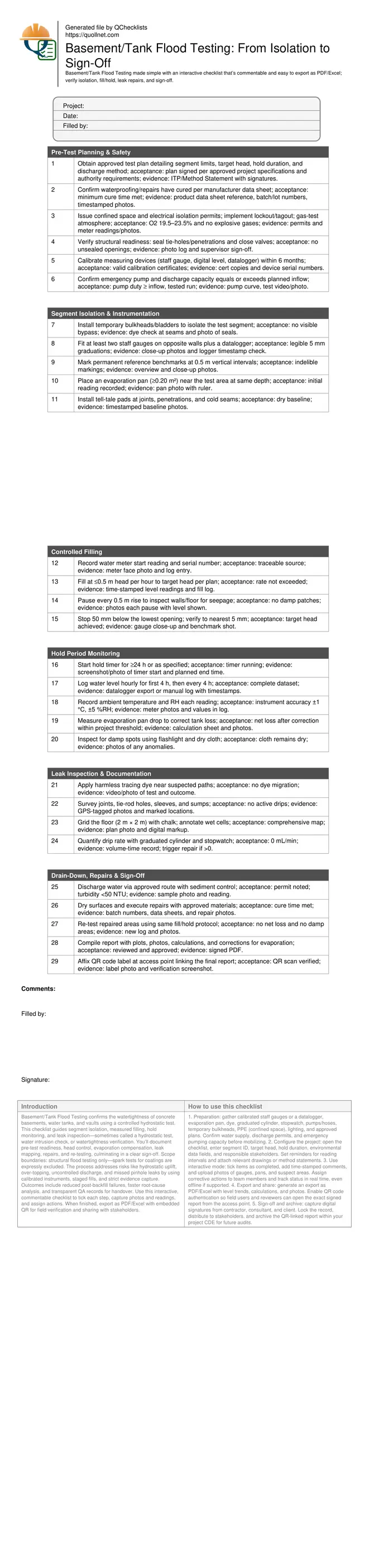
Basement/Tank Flood Testing Checklist
Definition: Basement/Tank Flood Testing is a structured QA procedure for contractors and inspectors to verify watertightness through isolated segment filling, hold monitoring, leak inspection, documented repairs, and formal sign-off.
- Defines isolation, fill-and-hold, inspection, repair, and sign-off steps
- Minimizes rework by catching leaks before backfill or commissioning
- Uses measured head, time-logged levels, and evaporation correction
- Interactive, commentable checklist with photo uploads, exports, and QR code
Basement/Tank Flood Testing confirms the watertightness of concrete basements, water tanks, and vaults using a controlled hydrostatic test. This checklist guides segment isolation, measured filling, hold monitoring, and leak inspection—sometimes called a hydrostatic test, water intrusion check, or watertightness verification. You’ll document pre-test readiness, head control, evaporation compensation, leak mapping, repairs, and re-testing, culminating in a clear sign-off. Scope boundaries: structural flood testing only—spark tests for coatings are expressly excluded. The process addresses risks like hydrostatic uplift, over-topping, uncontrolled discharge, and missed pinhole leaks by using calibrated instruments, staged fills, and strict evidence capture. Outcomes include reduced post-backfill failures, faster root-cause analysis, and transparent QA records for handover. Use this interactive, commentable checklist to tick each step, capture photos and readings, and assign actions. When finished, export as PDF/Excel with embedded QR for field verification and sharing with stakeholders.
- Prove watertightness before backfilling or commissioning by isolating segments, controlling fill rate and head, monitoring hold periods with calibrated gauges or dataloggers, and correcting for evaporation. Capture evidence with photos, readings, and signatures to reduce costly rework and disputes.
- Identify and quantify leaks precisely using dye tracing, drip volumetrics, and joint tell-tales. Document locations on a simple grid, implement targeted repairs with recorded batch data and cure times, then re-test to verify effectiveness and achieve clear acceptance without ambiguity.
- Interactive online checklist with tick, comment, and export features secured by QR code. Use it to standardize inspections across crews, maintain a defensible audit trail, and enable fast sharing with clients and authorities through authenticated reports linked directly onsite.
Pre-Test Planning & Safety
Segment Isolation & Instrumentation
Controlled Filling
Hold Period Monitoring
Leak Inspection & Documentation
Drain-Down, Repairs & Sign-Off
Why isolate segments and control head during flood testing
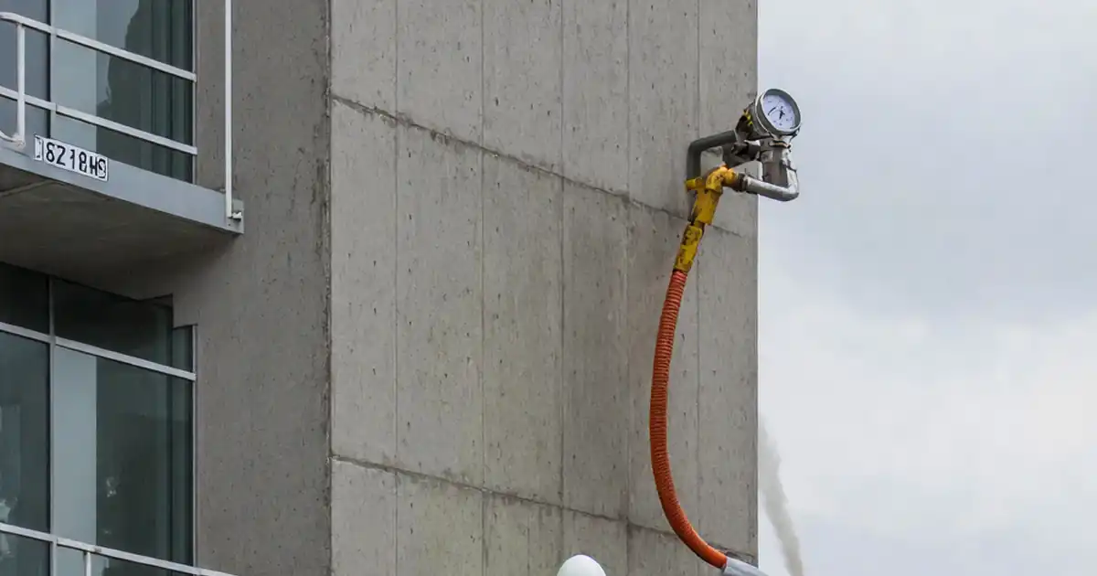
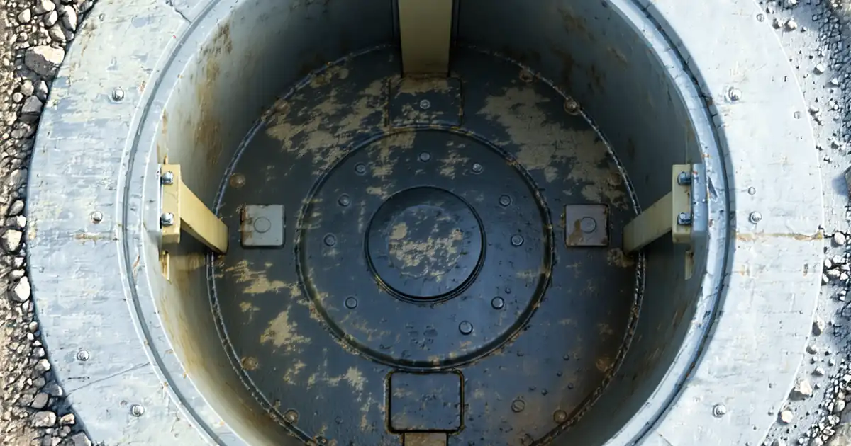
Segment isolation manages hydrostatic loads, keeps logistics practical, and localizes troubleshooting. Temporary bulkheads or inflatable bladders define the test boundary, preventing uncontrolled bypass that can mask defects. Controlled filling—limiting head rise—mitigates sudden uplift on slabs and avoids over-topping through low penetrations. Install redundant level references: at least two staff gauges plus an electronic logger reduce human error and help diagnose asymmetric deformation or localized leakage paths. On complex basements, test deeper sumps first, then adjacent bays in sequence, documenting benchmark elevations and water depths. Stopping 50 mm below the lowest opening preserves safety margin while achieving realistic service head. A well-drafted test plan clarifies target head, hold duration, and discharge controls, enabling smooth approvals and preventing delays.
- Isolate with bulkheads to prevent bypass and false passes
- Limit head rise to ≤0.5 m/h to protect structure
- Use dual gauges plus logger for reliable readings
- Stop 50 mm below the lowest opening for margin
- Stage adjacent bays to localize issues efficiently
Acceptance criteria: evaporation correction and trend-based decisions
Flood tests must separate true leakage from environmental effects. Place a nearby evaporation pan at matching water depth and record drops alongside tank levels. Subtract the pan loss from tank loss to calculate net leakage. Track ambient temperature and relative humidity; both influence evaporation rates and measurement uncertainty. A complete dataset—hourly early, then every four hours—supports trend analysis and confident decisions. Typical acceptance is zero measurable net loss and no damp surfaces, but always apply the project threshold per approved project specifications and authority requirements. Use consistent timestamps, unit conversions, and photographs of gauges to create a defensible record. If apparent loss equals or is less than the evaporation pan loss, you likely have no structural leakage.
- Correct tank loss by measured pan evaporation
- Log temperature and RH with each level reading
- Aim for zero net loss or within project threshold
- Ensure time-synced photos validate readings
- Trend graphs help reveal subtle anomalies
Leak mapping, targeted repairs, re-testing, and documentation
When leakage is observed, accuracy in mapping and quantification speeds resolution. Mark exact coordinates on a floor grid and circle suspect joints with paint for clarity in photos. Use harmless dye to trace flow paths, and quantify drips with a graduated cylinder and stopwatch for objective acceptance against thresholds. Drain through approved routes with sediment control, dry affected zones, and perform repairs using approved materials. Record batch numbers, cure times, and photos. Re-test the repaired segment using the identical protocol to confirm performance. Exclude spark testing—this checklist verifies watertightness by hydrostatic means only. Close out with a signed report, level trend charts, evaporation corrections, and a QR label onsite to tie physical access to the authenticated digital record.
- Map leaks on a consistent 2 m grid
- Use dye and drip volumetrics for clarity
- Record repair materials, batches, and cures
- Repeat full test to verify effectiveness
- Exclude spark tests; use hydrostatic evidence
How to Use This Flood Testing Checklist
- Preparation: gather calibrated staff gauges or a datalogger, evaporation pan, dye, graduated cylinder, stopwatch, pumps/hoses, temporary bulkheads, PPE (confined space), lighting, and approved plans. Confirm water supply, discharge permits, and emergency pumping capacity before mobilizing.
- Configure the project: open the checklist, enter segment ID, target head, hold duration, environmental data fields, and responsible stakeholders. Set reminders for reading intervals and attach relevant drawings or method statements.
- Use interactive mode: tick items as completed, add time-stamped comments, and upload photos of gauges, pans, and suspect areas. Assign corrective actions to team members and track status in real time, even offline if supported.
- Export and share: generate an export as PDF/Excel with level trends, calculations, and photos. Enable QR code authentication so field users and reviewers can open the exact signed report from the access point.
- Sign-off and archive: capture digital signatures from contractor, consultant, and client. Lock the record, distribute to stakeholders, and archive the QR-linked report within your project CDE for future audits.
Call to Action
- Start Checklist Tick off tasks, leave comments on items or the whole form, and export your completed report to PDF or Excel—with a built-in QR code for authenticity.
- Download Excel - Basement/Tank Flood Testing Checklist
- Download PDF - Basement/Tank Flood Testing Checklist
- View Image - Basement/Tank Flood Testing Checklist
Cite & Embed
“Basement/Tank Flood Testing Checklist by Quollnet”
with a link to
this source page.

FAQ
Question: How long should the flood test hold period be, and what head is typical?
Question: How do we correct for evaporation so we don’t misread a leak?
Question: When in the program should basement or tank flood testing occur?
Question: What should we do if we find a leak during the hold period?
Related Articles
Broader reading and guidance connected to this checklist topic.


Concrete Cube Test Register Excel Format – Pdf & Excel Sample

Safety In Construction: The Role Of Periodic Safety Checklists
Related Checklists
Keep the workflow moving with nearby templates chosen from similar checklist content.