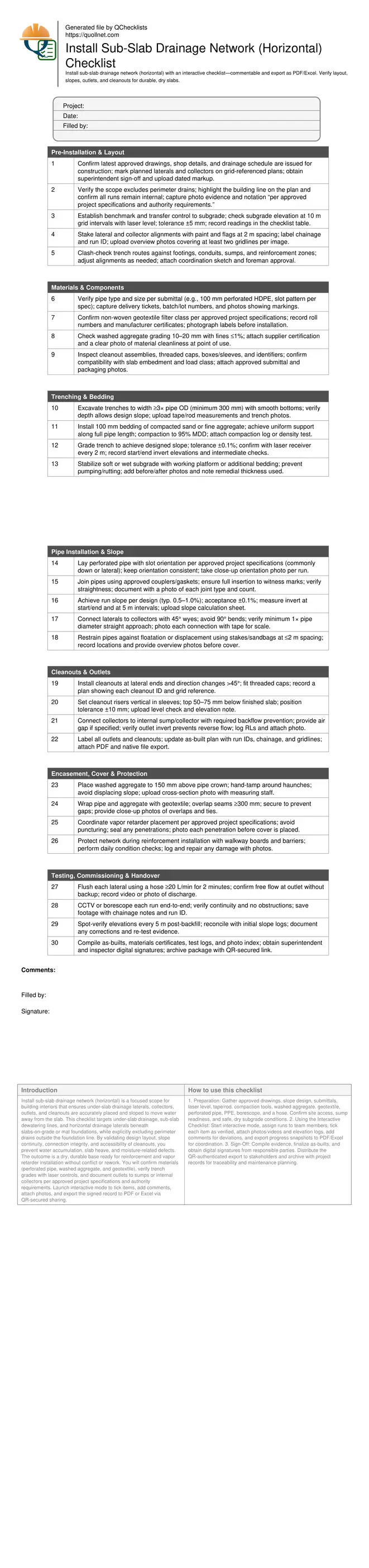
Install Sub-Slab Drainage Network (Horizontal)
Definition: Install sub-slab drainage network (horizontal) checklist guides contractors and inspectors through verifying internal drain layout, slopes, outlets, and cleanouts beneath slabs, excluding perimeter drains, to achieve dry, durable foundations.
- Confirm internal layout, slopes, outlets, and cleanouts match approved drawings.
- Use laser levels, slope logs, and photos to verify compliance.
- Prevent slab moisture issues by ensuring free-draining under-slab laterals.
- Interactive, commentable checklist with export and QR code verification.
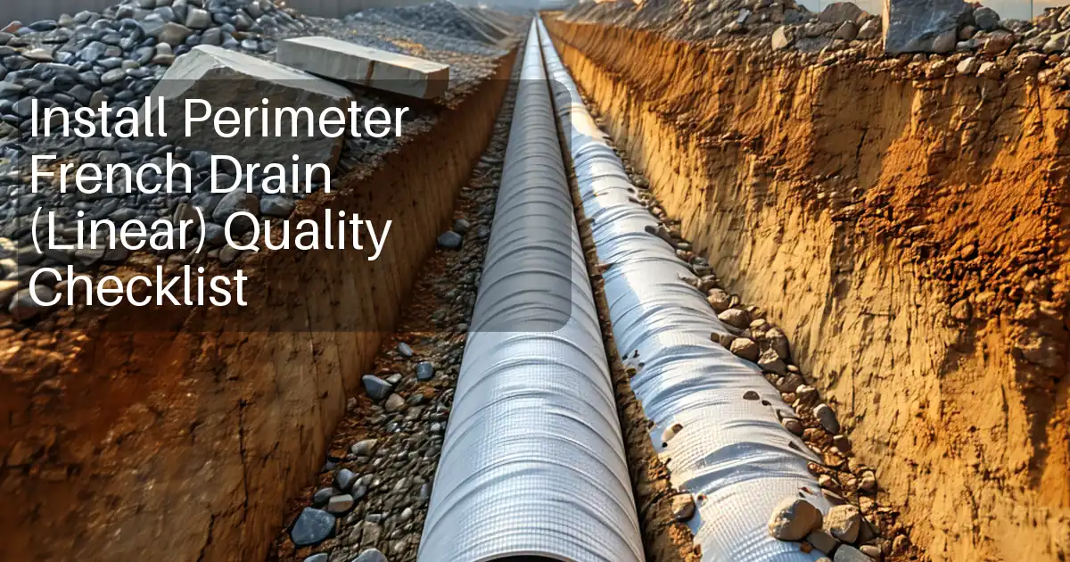
Install sub-slab drainage network (horizontal) is a focused scope for building interiors that ensures under-slab drainage laterals, collectors, outlets, and cleanouts are accurately placed and sloped to move water away from the slab. This checklist targets under-slab drainage, sub-slab dewatering lines, and horizontal drainage laterals beneath slabs-on-grade or mat foundations, while explicitly excluding perimeter drains outside the foundation line. By validating design layout, slope continuity, connection integrity, and accessibility of cleanouts, you prevent water accumulation, slab heave, and moisture-related defects. The outcome is a dry, durable base ready for reinforcement and vapor retarder installation without conflict or rework. You will confirm materials (perforated pipe, washed aggregate, and geotextile), verify trench grades with laser controls, and document outlets to sumps or internal collectors per approved project specifications and authority requirements. Launch interactive mode to tick items, add comments, attach photos, and export the signed record to PDF or Excel via QR-secured sharing.
- Ensure internal sub-slab drainage lines are accurately staked, consistently sloped, wrapped, and connected to sumps or internal collectors. This prevents standing water, slab curling, moisture ingress, and mold risks while supporting durable, code-aligned floor performance.
- Interactive online checklist with tick, comment, and export features secured by QR code.
- Capture decisive evidence: laser grade readings, invert elevation logs, materials certificates, photo and video of flow tests, and as-built plans with grid references. Reduce rework by clarifying scope boundaries and excluding perimeter drains from this workflow.
Pre-Installation & Layout
Materials & Components
Trenching & Bedding
Pipe Installation & Slope
Cleanouts & Outlets
Encasement, Cover & Protection
Testing, Commissioning & Handover
Plan the Internal Network for Slope and Access
A reliable sub-slab drainage network starts with precise internal layout and control. Stake the laterals and collectors on grid, confirm there are no clashes with footings, sleeves, or reinforcement, and verify that the entire network remains inside the foundation line. Establish accurate benchmarks and transfer elevations to the subgrade so trench grades deliver continuous fall to the internal sump or collector. Aim for a design slope of 0.5–1.0%, and enforce a construction tolerance of ±0.1% using a laser level and documented invert checks. Avoid sharp bends; specify 45° wyes for lateral tie-ins to maintain hydraulic performance and camera access. Early attention to cleanout placement and riser sleeves ensures tools can reach the entire system for maintenance. By building a complete evidence trail—marked-up drawings, elevation logs, and overview photos—you reduce risk of rework and safeguard the slab from moisture-driven failures. Keep perimeter drains out of scope to maintain clarity and avoid mixing standards.
- Keep all drains inside the foundation footprint.
- Set slope targets early and measure with lasers.
- Use 45° wyes for smooth hydraulic transitions.
- Locate cleanouts for full-length camera access.
- Record grid-referenced markups and invert logs.
Select Materials and Build for Durability
Material choices determine whether the sub-slab network stays free-flowing. Use perforated HDPE or equivalent pipe sized per design, with consistent slot orientation and secure couplers. Bed the pipe evenly on 100 mm compacted fine aggregate to 95% MDD, shape haunches, and confirm no point loading. Surround the pipe with washed 10–20 mm aggregate and wrap the envelope in a non-woven geotextile filter, overlapping seams by at least 300 mm to prevent fines migration. Keep the trench clean and stable; if the subgrade pumps, introduce a working platform or additional bedding. Install cleanouts at the ends of laterals and at direction changes to enable flushing and inspection. Set cleanout risers vertical in sleeves so final caps sit just beneath the finished slab for later access. Protect the network during reinforcement placement with boards and barriers, and coordinate vapor retarder placement without punctures.
- Confirm pipe size, slots, and couplers match submittals.
- Compact bedding and shape haunches for full support.
- Use washed aggregate and wrap with geotextile.
- Install cleanouts at ends and direction changes.
- Protect drains before steel and vapor retarder.
Test Performance and Document Handover
Commissioning verifies the network drains as designed. Flush each lateral with a constant flow and confirm discharge at the outlet without backup or crossflow. Push a borescope or CCTV through every run to confirm continuity, joint integrity, and clean interiors. After backfill, re-check representative elevations to confirm slopes remain within tolerance, then reconcile with initial logs. Label and record every cleanout and outlet on an as-built plan with grid references and chainage. Package test videos, photos, material certificates, and slope tables for sign-off. Obtain digital signatures from the superintendent and inspector, and archive the bundle with a QR-secured link for future maintenance. This record simplifies warranty claims, enables quick troubleshooting, and provides clear evidence that only the internal system—excluding perimeter drains—was constructed and verified per approved project specifications and authority requirements.
- Flush flows and verify clear, continuous discharge.
- CCTV runs to check joints and obstructions.
- Spot-check slopes post-backfill for tolerance.
- Label cleanouts and outlets on as-builts.
- Archive a QR-secured, signed dossier.
How to Use This Interactive Checklist
- Preparation: Gather approved drawings, slope design, submittals, laser level, tape/rod, compaction tools, washed aggregate, geotextile, perforated pipe, PPE, borescope, and a hose. Confirm site access, sump readiness, and safe, dry subgrade conditions.
- Using the Interactive Checklist: Start interactive mode, assign runs to team members, tick each item as verified, attach photos/videos and elevation logs, add comments for deviations, and export progress snapshots to PDF/Excel for coordination.
- Sign-Off: Compile evidence, finalize as-builts, and obtain digital signatures from responsible parties. Distribute the QR-authenticated export to stakeholders and archive with project records for traceability and maintenance planning.
Call to Action
- Start Checklist Tick off tasks, leave comments on items or the whole form, and export your completed report to PDF or Excel—with a built-in QR code for authenticity.
- Download Excel - Sub-Slab Drainage Network Installation (Horizontal)
- Download PDF - Sub-Slab Drainage Network Installation (Horizontal)
- View Image - Sub-Slab Drainage Network Installation (Horizontal)
Cite & Embed
“Sub-Slab Drainage Network Installation (Horizontal) by Quollnet”
with a link to
this source page.

FAQ
Question: What slope should I use for sub-slab drainage laterals under a slab-on-grade?
Question: Where should cleanouts be located for effective maintenance and inspection?
Question: How do I prevent fines from clogging the sub-slab drainage network over time?
Question: What tests prove the network is unobstructed before pouring the slab?
Related Articles
Broader reading and guidance connected to this checklist topic.
Requisition Form: Materials, Services, Budget Control, And Logs

Handmade Ceramics And Technique

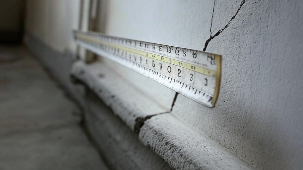
Is The Crack You See On Your Wall Serious Or Minor Cosmetic Issue?
Related Checklists
Keep the workflow moving with nearby templates chosen from similar checklist content.