Method Statement: Installation of HDPE Soil, Waste & Vent (SWV) Vertical Stacks – Method Statement
AI-assisted method statement with matching ITP, PDF download, and Excel export.
More than a static template
Unlike a downloadable Word or PDF template, this method statement is an AI-assisted editable starting point connected directly to a matching Inspection and Test Plan. Every section is structured, project-adaptable, and ready to export.
- AI-assisted drafting — Customize every section with AI for your specific project scope.
- Linked ITP — A matching inspection and test plan is generated alongside the method statement.
- Multiple export formats — Download as a formatted PDF or editable Excel spreadsheet.
- Editable starting point, not a final document — Review, verify, and adjust all content against your project requirements before use.
Static template vs. Quollnet workflow
| Feature | Static template | Quollnet |
|---|---|---|
| Project-specific content | Manual fill-in required | AI-assisted customization |
| Linked ITP | Separate document, no link | Matching ITP included |
| Export formats | Usually PDF only | PDF and Excel |
| Structured sections | Free-form layout | 13 standardized sections |
| Saved to your account | Local file only | Cloud-saved, reusable |
| Content accuracy | You verify everything | AI-assisted, you still verify |
| Cost | Often free but time-intensive | Free to customize and download |
What you can customize
When you save this method statement to your account, every section becomes editable. The following 13 sections are included:
- Scope — Defines the activity and its boundaries.
- References — Standards, specifications, and drawings.
- Responsibilities — Roles and accountabilities.
- Resources — Labour, plant, and equipment summary.
- Materials — Materials and compliance requirements.
- Equipment — Tools and equipment details.
- Prerequisites — Hold points and pre-conditions.
- Method sequence — Step-by-step construction sequence.
- Safety controls — HSE risk controls and PPE.
- Environmental controls — Environmental mitigation measures.
- QA/QC — Quality inspection and test requirements.
- ITP — Inspection and Test Plan table (has its own page).
- Attachments — Referenced drawings and documentation.
Why this method statement is used
This method statement is used to define and communicate the approved procedure for carrying out method statement: installation of hdpe soil, waste & vent (swv) vertical stacks on site. It ensures the work is planned in advance, the correct resources and controls are in place, and all personnel understand responsibilities, sequence, quality requirements, and safety controls before work begins. It aligns site execution with the documented scope and acceptance expectations.
Who uses this method statement
This method statement is used by contractors, site supervisors, project engineers, QA/QC engineers, HSE officers, consultants, and client representatives. It serves as a shared reference for planning, execution, supervision, inspection, and approval of the activity on site.
When it is prepared and submitted
The method statement is prepared before the work activity starts and submitted as part of the pre-construction documentation package for review and approval.
Who reviews or approves it
The method statement is usually submitted to the client representative, consultant, resident engineer, or project management consultant for review and approval before the work commences.
Important approval note
This method statement is an AI-assisted editable starting point, not a pre-approved document. Before use on any project, all content must be reviewed and approved by the relevant parties (superintendent, principal contractor, or client representative) in accordance with your contract and project quality plan.
For example: if your specification requires a departure from a referenced standard, that departure must be documented and approved separately — this method statement will not capture that automatically. Always verify against your applicable drawings, specifications, and regulatory requirements.
Method statement content
Scope of Works
Inclusions
- Supply, preparation, and installation of HDPE SWV vertical stacks including soil, waste, and vent risers.
- Jointing by electrofusion (EF) couplers/saddles and/or butt-fusion as specified and approved.
- Installation of expansion couplings/compensators and anchor/guide supports to accommodate thermal movement.
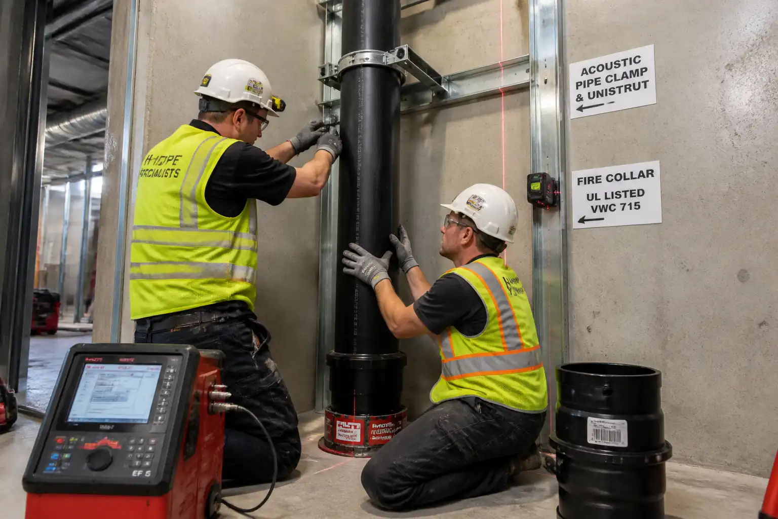
- Installation of soundproofing pipe clamps with elastomeric inserts; setting of support spacing and anchor points.
- Formation of structural penetrations (cored) or use of cast-in devices; installation of sleeves where required.
- Fire-stopping at floor/wall penetrations using tested and approved systems to achieve required FRL.
- Vertical alignment setting-out and plumbness verification of stacks.
- Temporary capping/blanking and hydrostatic or air testing of the completed stacks.
- Labeling, identification, and as-built documentation.
Exclusions
- Fixture connection beyond specified take-off points (unless stated).
- External site drainage and civil works (unless stated).
- Permanent access platforms and builder’s works not defined in MEP scope.
Performance Targets [Verify per project specifications]
- Leak-free under test conditions.
- Plumbness: ≤ 2 mm per meter or ≤ 10 mm total per full-height stack, whichever governs.
- Support spacing and expansion allowances per manufacturer; typical vertical spacing ≤ 1.5 m for HDPE stacks.
- Fire integrity at penetrations equal to or greater than base element FRL.
References & Standards
| Document Type | Reference / Number | Revision | Notes |
|---|---|---|---|
| Standard | BS EN 1519-1 | ||
| Standard | BS EN 12056 | ||
| Standard | ISO 21307 | ||
| Standard | ISO 13950 | ||
| Standard | ISO 12176 (series) | ||
| Standard/Guide | MSS SP-58/69; Manufacturer | Support design loads and spacing to be verified by structural calculations and manufacturer data. | |
| Standard/Guide | DIN 4109; Manufacturer | ||
| Standard | EN 1366-3; ASTM E814/UL1479 | ETA/CE/UL listings required. | |
| Standard | ISO 17123 | ||
| Plan/Regulations | Project/Local |
Responsibilities
| Role | Responsibility | Name / Party |
|---|---|---|
| PM | Approvals & Resources | Main Contractor |
| CM/SE | Execution & Coordination | Main Contractor |
| QA/QC | Quality Control | Main Contractor |
| HSE | HSE Oversight | Main Contractor |
| Supervisor | Welding Supervision | Main Contractor/Subcontractor |
| Applicator | Firestop Installation | Specialist Subcontractor |
| Surveyor | Setting-Out | Main Contractor |
| TPI | Independent Verification | Independent |
Resources
| Resource Type | Description | Quantity | Remarks |
|---|---|---|---|
| Labor | Trained and certified for EF and butt-fusion on HDPE SWV. | As per look-ahead plan | |
| Labor | Manufacturer-approved applicators for specified systems. | As required | |
| Labor | Provide safe access and lifting for risers within shafts. | As required |
Materials
| Material | Specification / Grade | Quantity | Remarks |
|---|---|---|---|
| HDPE | As BOQ | ||
| HDPE EF | As BOQ | ||
| HDPE | As BOQ | ||
| Per riser design | |||
| Per support plan | |||
| As required | |||
| Per penetration | |||
| As required |
Equipment
| Equipment | Capacity / Type | Quantity | Inspection Required |
|---|---|---|---|
| ≥1 per crew | |||
| As required | |||
| As required | |||
| As required | |||
| As required | |||
| As required | |||
| As required |
Prerequisites & Pre-Start Checks
Approvals & Documentation
- Approved shop drawings, riser diagrams, penetration schedules, and coordinated BIM model.
- Approved material submittals for HDPE system, fusion equipment, clamps, anchors, and firestop systems.
- Issued WPS for EF and butt-fusion, manufacturer parameter tables, and technician certifications.
- ITP and checklists issued; hold/witness points agreed with Client/TPI.
Site Readiness
- Penetration locations surveyed and marked; clash-free clearances confirmed with other trades.
- Access platforms/scaffolds installed and inspected; shaft edge protection completed.
- Utilities scanning/clearance completed for coring areas; permits issued [Verify per project HSE plan and local regulations].
- Power supply with RCD available for EF/controller and coring rig.
Materials & Equipment
- Pipes and fittings inspected for damage and stored straight on clean supports, protected from heat/UV per manufacturer.
- Fusion machines calibrated; cleaning wipes, scrapers, clamps, test plugs on hand.
- Firestop materials available with matching listing for substrate and pipe OD/SDR; labels prepared.
Toolbox Talks
- Task-specific TBTs delivered for shaft work, coring, fusion burns, manual handling, and testing hazards.
Hold Points (typical)
- H1: First-of-kind joint (EF and butt-fusion) setup and parameter verification.
- H2: Pre-close of firestop penetrations.
- H3: Stack hydro/air test setup and results review.
Method Sequence
| Step | Activity | Description | Responsibility | Inspection / Hold Point |
|---|---|---|---|---|
| 1 | Setting-Out & Coordination | Confirm riser centerlines from gridlines; check clear space in shafts; mark support/anchor points on every level. | Surveyor / Site Engineer | Layout check |
| 2 | Access & Edge Protection | Install/verify scaffold towers, toe boards, debris netting in shafts, and fall arrest anchor points. | Construction Manager | Scaffold inspection |
| 3 | Penetration Formation (Core Drilling) | Scan slab/wall, mark cores, rig fixings, wet core to required diameter; collect slurry; install sleeves where specified. | Specialist Coring Crew | Permit-to-core; dimensional check |
| 4 | Pipe Cutting & Preparation | Measure, mark square cuts; cut with rotary cutter; deburr; for EF, scrape oxidized layer (~0.2 mm) over coupling length; clean with approved wipes; dry-fit. | Fusion Technician | Visual prep check |
| 5A | Butt-Fusion Jointing (if specified) | Clamp pipes; face ends to parallel/clean; heat with plate at WPS temp; achieve bead-up; change-over; apply fusion pressure; hold under clamp until cooled per thickness; do not disturb. | Fusion Supervisor & Technician | Hot plate temp check; bead inspection |
| 5B | Electrofusion Jointing (if specified) | Re-round and clamp; insert to depth marks; scan fitting barcode; energize per controller; maintain clamping during full cooling; verify melt indicators; download data log. | Fusion Supervisor & Technician | EF parameter verification; clamp check |
| 6 | Stack Erection & Alignment | Assemble base to top in manageable lifts (e.g., 3 m); use chain blocks; check plumb each lift with laser; install temporary caps at open ends. | Site Engineer / Crew | Plumbness survey |
| 7 | Expansion Provision | Install expansion couplings/compensators; set mid-stroke at installation temperature; position anchors and guides as per design to direct movement. | Site Engineer | Check stroke setting and anchor locations |
| 8 | Supports & Acoustic Clamps | Install anchor clamp at base and at each floor (as design); install guide clamps between floors. Tighten to hold but not crush liner; maintain stand-off to avoid structure contact. | Site Engineer | Support spacing and torque |
| 9 | Branch Connections | Install tees/saddles at marked levels; ensure gradient for horizontal branches (typ. 1:60–1:40) [Verify]; support near junctions. | Fusion Technician | Level/gradient check |
| 10 | Fire-Stopping of Penetrations | Prepare substrate; fit fire collars/wraps as per listing (underside of slabs; sometimes topside as required); seal annulus with approved sealant/mortar; affix label with system ID and FRL. | Approved Firestop Applicator | Firestop pre-close and final |
| 11 | Testing (Hydrostatic or Air) | Cap stack; fill from lowest point; establish test head above highest fitting; hold and inspect all joints. Alternative air test only if permitted by authority/specification. | QA/QC Engineer | Witness test |
| 12 | Identification & Handover | Install labels/flow arrows; update as-builts; submit fusion logs, calibration certs, firestop records, test certificates. | Project Engineer | Document review |
Health, Safety & Risk Controls
Key Hazards and Controls
1) Working at height/shaft edges
- Consequence: Falls leading to serious injury or fatality.
- Engineering/Procedural Control: Full edge protection with guardrails and toe boards; debris netting inside shafts; use certified mobile towers; restrain tools; exclusion zone below. Permit-to-work for work at height.
- PPE: Full body harness with double lanyard when required, hard hat with chin strap, safety boots, gloves.
- Collective Measure: Scaffold with green tag; fixed anchor points; rescue plan.
- Inspection/Permit/Supervision: Daily scaffold inspections; permit-to-work; supervisor oversight. [Verify per project HSE plan and local regulations]
2) Core drilling with embedded services
- Consequence: Utility strike, electric shock, flooding, structural damage.
- Control: GPR/ferroscan and service drawings; pilot holes where safe; RCD-protected drilling equipment; secure rig anchorage; wet coring with slurry containment.
- PPE: Eye/face shield, hearing protection, waterproof gloves, dielectric boots.
- Collective Measure: Exclusion zone; spill berms; lockable isolation where needed.
- Inspection/Permit: Permit-to-core; equipment pre-use checks; anchor verification.
3) Heat exposure from fusion tools (burns/fire)
- Consequence: Burns, fire.
- Control: Designated hot zone; heat-resistant mats; controlled access; cooling stand for hot plate; no flammables nearby; fire extinguisher (CO2/foam) on hand.
- PPE: Heat-resistant gloves, long sleeves, eye protection.
- Collective Measure: Barriers/signage around fusion area.
- Inspection/Permit: Hot work permit if required by site; supervisor present during first-of-kind joints.
4) Electrical risks from EF controller and coring rig
- Consequence: Electric shock.
- Control: RCD/GFCI 30 mA; PAT-tested equipment; dry location with IP-rated covers; cables routed overhead or protected.
- PPE: Dielectric gloves when connecting; dry PPE.
- Collective Measure: Lockable distribution board.
- Inspection/Permit: Daily visual checks; PAT labels in date.
5) Manual handling of long HDPE sections
- Consequence: Strains, crush injuries.
- Control: Team lifts and tag lines; use chain blocks and slings; plan lift path; cut to manageable lengths.
- PPE: Grip gloves, safety boots.
- Collective Measure: Mechanical aids prioritized.
- Inspection/Permit: Lift plan for complex lifts; gear certificates valid.
6) Falling objects down riser shafts
- Consequence: Impact injuries to personnel below.
- Control: Tool lanyards; toe boards; debris netting; exclusion zones; material hoists with gates.
- PPE: Hard hats.
- Collective Measure: Segregation and signage.
- Inspection/Permit: Supervisor to enforce exclusion zones.
7) Testing under pressure/head
- Consequence: Plug ejection, flooding.
- Control: Rated test plugs with secondary retention (chains); gradual fill/venting; secure caps; barriers.
- PPE: Eye protection, boots, gloves.
- Collective Measure: Exclusion zone during pressurization.
- Inspection/Permit: Test method statement/permit; witness by QA/QC/TPI.
8) Chemical exposure (firestop sealants/cleaners)
- Consequence: Skin/eye irritation, respiratory issues.
- Control: Use low-VOC products; ventilation; follow SDS; avoid skin contact.
- PPE: Nitrile gloves, goggles, masks if required.
- Collective Measure: Local exhaust/ventilation in enclosed shafts.
- Inspection/Permit: SDS available; COSHH assessment completed.
9) Noise and vibration from coring
- Consequence: Hearing damage, nuisance.
- Control: Hearing protection; time restrictions; anti-vibration gloves; job rotation.
- PPE: Hearing protection.
- Collective Measure: Acoustic barriers where feasible.
- Inspection/Permit: Noise monitoring if required.
Environmental Controls
Environmental Risks and Mitigations
- Coring slurry and wastewater: Use wet vac/slurry collector; store in labeled containers; dispose via licensed facility; neutralize pH if required [Verify per project EMS].
- HDPE offcuts and packaging: Segregate clean plastic for recycling; minimize offcuts by optimized cutting plans; return pallets.
- Dust/particulates: Wet methods and vacuum extraction; regular housekeeping; sealed chutes for waste.
- Noise: Plan noisy works during permitted hours; use mufflers and acoustic screens where practicable.
- Energy use: Use efficient EF units; switch off idle equipment; consider battery RCDs.
- Spills/leaks (oils/coolants): Store on drip trays; spill kits adjacent; immediate cleanup and reporting.
- Firestop chemical waste: Dispose per SDS; do not wash into drains.
- Visual impact and housekeeping: Keep shafts clear; remove debris daily; maintain clear egress routes.
Quality Assurance & Control
Documentation & Controls
- Use approved WPS and manufacturer parameter tables for all fusion joints.
- Calibration: EF controller and butt-fusion heater/facer within validity; verification of hot-plate temperature before shift.
- Material traceability: Record pipe heat/batch numbers and EF fitting barcodes; maintain weld numbers per stack.
- Training: Fusion technicians certified; firestop installers approved by manufacturer.
- Inspection hold/witness points per ITP; do not conceal works before inspection.
Workmanship Criteria [Verify per project specifications]
- EF Joints: Proper scraping (≈0.2 mm), clean/dry surfaces, clamp throughout weld and full cooling; indicators fully actuated; controller data log compliant.
- Butt Joints: Even double-roll bead, correct bead-up and fusion pressure per WPS; misalignment ≤ 10% t or ≤ 1 mm; no underbead voids or contamination; cooling undisturbed.
- Alignment: Plumbness ≤ 2 mm/m; branches with designed falls (typ. 1:60–1:40).
- Supports: Vertical spacing ≤ 1.5 m; anchor at each floor; guide supports to permit axial movement; clamp liners intact.
- Expansion: Calculated ΔL satisfied with available stroke; expansion joint set at mid-stroke at installation temperature; anchors/guides as per detail.
- Firestop: System matches listing; correct fixings and annular gap; labeling in place; FRL achieved.
Nonconformance & Corrective Action
- Record NCRs for leaks, failed joints, misalignment, missing firestop labels, or out-of-date calibrations.
- Rectify by cut-out and re-welding or replacing fittings; re-test affected sections; re-inspect firestop.
Records for Handover
- Approved MS/ITP; material submittals and CoCs; calibration certs; EF data logs; weld maps; test certificates; firestop ITRs and labels; as-built drawings; O&M manuals.
Attachments
Attached/Referenced Documents
- Typical details: Riser support and expansion arrangement (ANCHOR/GUIDE layouts) [Drawing No. — Verify].
- Firestop system data sheets and listings (UL/ETA) for each penetration condition.
- Fusion WPS and parameter charts (EF and butt-fusion) by manufacturer.
- Prestart checklists: Materials receipt, equipment calibration, EF/Butt joint checklist.
- ITRs: Supports, Expansion, Firestop, Testing.
- Risk assessment and lifting plan for riser erection.
- As-built templates for weld mapping and labeling.
Note: All attachments to be controlled documents with current revisions.
This content is a read-only public reference. Download or customize to get an editable version.
ITP preview
The first inspection activities from the linked ITP for Method Statement: Installation of HDPE Soil, Waste & Vent (SWV) Vertical Stacks:
| Activity | Inspection / Test | Acceptance Criteria | Responsibility | Record |
|---|---|---|---|---|
| Material receipt (pipes/fittings) | CoC/Delivery inspection | Conformity to BS EN 1519-1; no damage; correct OD/SDR; traceability labels present. | QA/QC Engineer | Material inspection report, CoC |
| Equipment calibration (EF & butt-fusion) | Calibration verification | Valid calibration (≤ 12 months) [Verify]; hot plate temperature within WPS; controller self-test passed. | QA/QC Engineer | Calibration certs, pre-use checklist |
| Pre-install coordination & setting-out | Survey/marking verification | Locations per approved drawings; tolerances within 5 mm [Verify]. | Site Engineer | Setting-out report |
Showing 3 of 12 inspection activities. View full ITP →
Related Inspection and Test Plan
An Inspection and Test Plan (ITP) is available for Method Statement: Installation of HDPE Soil, Waste & Vent (SWV) Vertical Stacks. The ITP defines the inspection activities, acceptance criteria, hold and witness points, responsible parties, and records required to verify the work described in this method statement.
View the Method Statement: Installation of HDPE Soil, Waste & Vent (SWV) Vertical Stacks ITP →Frequently asked questions
Continue with related Quollnet resources connected to this method statement.