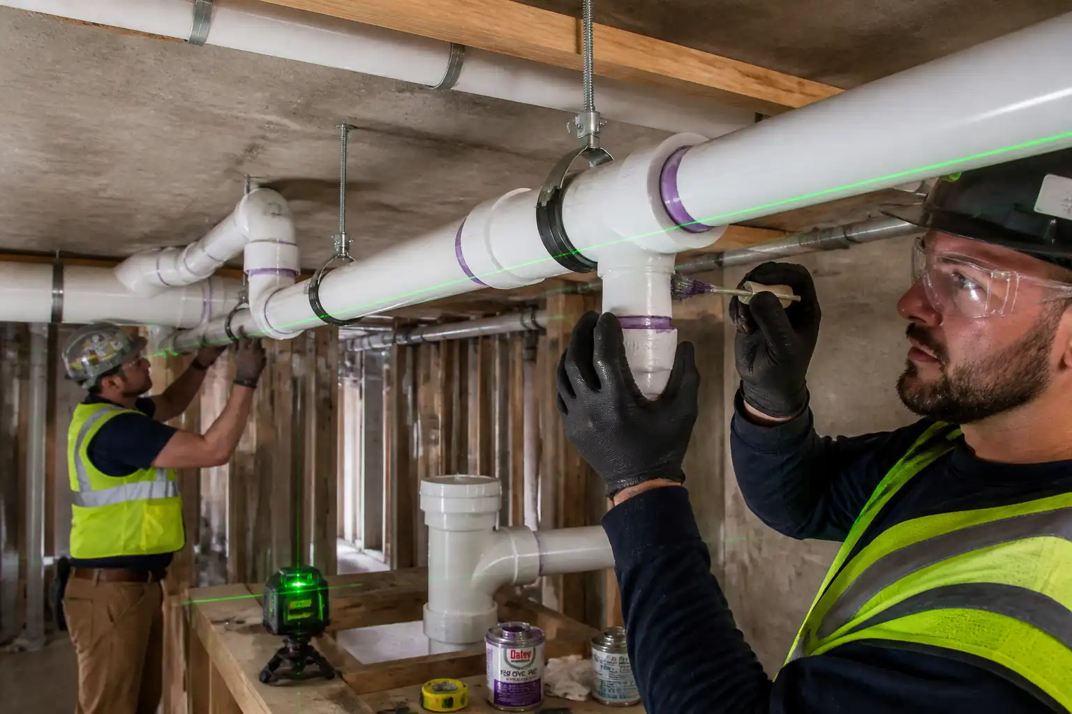

Inspection and Test Plan for Method Statement: Installation of Internal uPVC Soil, Waste and Vent (DWV) Piping Networks
AI-assisted inspection and test plan connected to a method statement, with PDF and Excel export.
More than a static template
Unlike a downloadable Word or PDF template, this ITP is an AI-assisted editable starting point directly connected to its method statement. Every inspection activity, hold point, and acceptance criterion is structured and ready to adapt to your project.
- AI-assisted customization — Tailor inspection activities and acceptance criteria to your specific project scope.
- Linked method statement — This ITP is connected to the corresponding method statement describing the work sequence.
- Multiple export formats — Download as a formatted PDF or editable Excel spreadsheet.
- Editable starting point, not a final document — Review and verify all content against your project specifications and standards before use.
What you can customize
When you save this ITP to your account, every inspection row becomes editable. You can add, remove, or modify:
- Inspection activity — Description of what is being inspected.
- Inspection type — Hold point (H), Witness point (W), Review (R), or Monitor (M).
- Responsibility — Contractor, subcontractor, engineer, or client.
- Frequency — How often the inspection occurs.
- Acceptance criteria — Referenced standard or specification requirement.
- Records — Forms, test reports, or checklists required as evidence.
Why this ITP is used
To ensure installed DWV systems meet standards, project specs, and functional performance for leak tightness and self-cleansing gradients.
Who uses this inspection and test plan
Contractor supervisors and QA/QC, Engineer/Consultant representatives, and third-party inspectors where specified.
When this ITP is prepared and submitted
From material delivery through installation, curing, pressure testing, and final acceptance.
Who receives or approves this ITP
Engineer/Consultant for review and approval.
Inspection scope
Covers materials, anchors/hangers, pipe preparation and jointing, gradient/alignment, cleanouts, firestopping, and leak testing.
Typical hold, witness, and review points
Anchor layout; first-of-kind jointing and branch configuration; start and completion of water/air tests; firestopping installations.
Typical inspection records
Material inspections, anchor tests, jointing checklists, slope sheets, cleanout logs, firestop reports, test certificates, and as-builts.
Important approval note
This ITP is an AI-assisted editable starting point, not a pre-approved document. Before use on any project, all inspection activities, hold points, and acceptance criteria must be reviewed and approved by the relevant parties (superintendent, principal contractor, or client representative) in accordance with your contract and project quality plan.
Always verify acceptance criteria against your applicable drawings, specifications, and regulatory requirements. Hold points must be confirmed with the relevant authority before work proceeds past that point.
Inspection and test plan
| Activity | Inspection / Test | Acceptance Criteria | Responsibility | Record |
|---|---|---|---|---|
| Material receipt and identification | Verify standards, sizes, markings; review COC and SDS | Conformity to BS EN 1329-1/ASTM D2665; no damage/warping; correct batches logged | Contractor QA/QC; Witness by Engineer | Material inspection report, photos |
| Anchor/hanger layout and installation | Check spacing, edge distances, embedment, torque | Per manufacturer data and project design; corrosion class correct | Contractor; Witness by Engineer | Anchor/hanger inspection checklist, torque log |
| Anchor proof load test (if required) | Apply proof load (e.g., 1.5× service load for 15 s) to sample anchors [Verify] | No pull-out or displacement >1 mm; no substrate cracking | Contractor with third-party if specified; Witness by Engineer | Pull test certificates |
| Pipe cutting/deburring/chamfer | Visual and measurement check | Square cuts; chamfer 10–15°; edges deburred; cleanliness verified | Contractor | In-process QC checklist |
| Solvent cement jointing | Check primer use (if required), cement coverage, insertion depth, alignment | Full 360° bond; correct insertion depth (−0/+3 mm); uniform bead; no voids | Contractor; Witness first 10 joints per shift by QA/QC | Jointing inspection sheet; batch log |
| Slope and alignment verification | Laser/level checks every 2–3 m and at mid-spans | Continuous fall; slope within ±0.2% or ±3 mm/m; no sag/backfall | Contractor QA/QC; Witness by Engineer as required | Slope verification sheet; photos |
| Branch fittings and angle compliance | Visual configuration check | 45° wyes/combination fittings used; long-sweep bends; no short 90° on horizontal-to-horizontal | Contractor; Witness by Engineer for first-of-kind | Inspection checklist; photos |
| Cleanouts (location and accessibility) | Verify spacing and clearance; access panels installed | Spacing ≤12–15 m on mains; clearance ≥450 mm; caps removable | Contractor; Witness by Engineer | Cleanout schedule and photos |
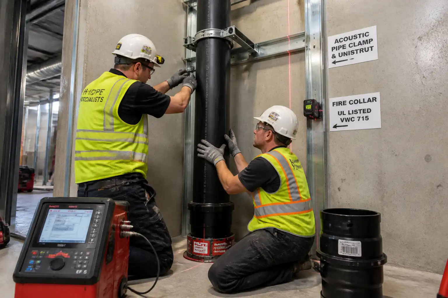
| Firestopping at penetrations | Check against approved UL/ETA system detail | System ID matches site conditions; correct sealant/collar; labeling complete | Firestopping Specialist; Witness by Engineer/Third-party if required | Firestop inspection report; photos |
| System test – water or air | Water head test or low-pressure air test | No leakage; no pressure/level drop per approved test regime [Verify] | Contractor; Witness by Engineer | Test certificates; gauge/manometer readings; photos |
| Final visual and functional checks | Flush/visual inspection; check labels and as-builts | Free flow; correct labeling; documentation complete | Contractor; Witness by Engineer | Final inspection report; punch list closeout |
This table is a read-only public reference. Download the PDF or Excel version, or customize this ITP to edit it for your project.
Frequently asked questions
Related method statement
This Inspection and Test Plan is associated with the Method Statement: Installation of Internal uPVC Soil, Waste and Vent (DWV) Piping Networks method statement, which describes the step-by-step construction sequence, resources, materials, equipment, safety controls, and environmental controls for this activity.
View the Method Statement: Installation of Internal uPVC Soil, Waste and Vent (DWV) Piping Networks method statement →Continue with related inspection, method statement, article, and checklist resources.