
Method Statement: Installation of Roof Rainwater Drainage Outlets and Vertical Downspouts (uPVC/HDPE) with Waterproofing Integration and Flood Testing – Method Statement
AI-assisted method statement with matching ITP, PDF download, and Excel export.
More than a static template
Unlike a downloadable Word or PDF template, this method statement is an AI-assisted editable starting point connected directly to a matching Inspection and Test Plan. Every section is structured, project-adaptable, and ready to export.
- AI-assisted drafting — Customize every section with AI for your specific project scope.
- Linked ITP — A matching inspection and test plan is generated alongside the method statement.
- Multiple export formats — Download as a formatted PDF or editable Excel spreadsheet.
- Editable starting point, not a final document — Review, verify, and adjust all content against your project requirements before use.
Static template vs. Quollnet workflow
| Feature | Static template | Quollnet |
|---|---|---|
| Project-specific content | Manual fill-in required | AI-assisted customization |
| Linked ITP | Separate document, no link | Matching ITP included |
| Export formats | Usually PDF only | PDF and Excel |
| Structured sections | Free-form layout | 13 standardized sections |
| Saved to your account | Local file only | Cloud-saved, reusable |
| Content accuracy | You verify everything | AI-assisted, you still verify |
| Cost | Often free but time-intensive | Free to customize and download |
What you can customize
When you save this method statement to your account, every section becomes editable. The following 13 sections are included:
- Scope — Defines the activity and its boundaries.
- References — Standards, specifications, and drawings.
- Responsibilities — Roles and accountabilities.
- Resources — Labour, plant, and equipment summary.
- Materials — Materials and compliance requirements.
- Equipment — Tools and equipment details.
- Prerequisites — Hold points and pre-conditions.
- Method sequence — Step-by-step construction sequence.
- Safety controls — HSE risk controls and PPE.
- Environmental controls — Environmental mitigation measures.
- QA/QC — Quality inspection and test requirements.
- ITP — Inspection and Test Plan table (has its own page).
- Attachments — Referenced drawings and documentation.
Why this method statement is used
This method statement is used to define and communicate the approved procedure for carrying out method statement: installation of roof rainwater drainage outlets and vertical downspouts (upvc/hdpe) with waterproofing integration and flood testing on site. It ensures the work is planned in advance, the correct resources and controls are in place, and all personnel understand responsibilities, sequence, quality requirements, and safety controls before work begins. It aligns site execution with the documented scope and acceptance expectations.
Who uses this method statement
This method statement is used by contractors, site supervisors, project engineers, QA/QC engineers, HSE officers, consultants, and client representatives. It serves as a shared reference for planning, execution, supervision, inspection, and approval of the activity on site.
When it is prepared and submitted
The method statement is prepared before the work activity starts and submitted as part of the pre-construction documentation package for review and approval.
Who reviews or approves it
The method statement is usually submitted to the client representative, consultant, resident engineer, or project management consultant for review and approval before the work commences.
Important approval note
This method statement is an AI-assisted editable starting point, not a pre-approved document. Before use on any project, all content must be reviewed and approved by the relevant parties (superintendent, principal contractor, or client representative) in accordance with your contract and project quality plan.
For example: if your specification requires a departure from a referenced standard, that departure must be documented and approved separately — this method statement will not capture that automatically. Always verify against your applicable drawings, specifications, and regulatory requirements.
Method statement content
Scope
Work Scope
- Install roof rainwater drainage outlets (gravity type) including waterproofing flange integration, clamping ring tightening/verification, and leaf strainer placement.
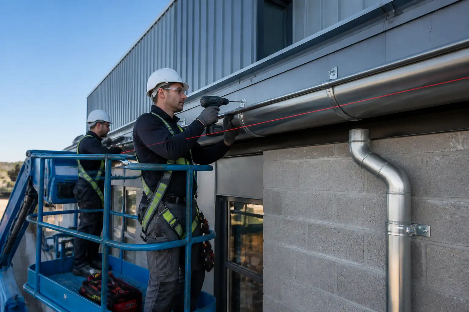
- Install vertical downspouts and horizontal collectors in uPVC or HDPE heavy-duty stormwater piping, including supports, anchors, expansion provisions, access fittings, and terminations to rainwater stacks or external discharge points.
- Coordinate and execute penetrations, sleeves, and firestopping/acoustic treatments where downspouts pass through slabs/walls [Verify per project fire strategy and acoustic specs].
- Conduct outlet flood testing, downpipe sectional water testing, and functional flow tests.
- Deliver complete QA/QC documentation: material approvals, inspection records, torque logs, fusion logs, test certificates, as-built redlines, and O&M manuals.
Exclusions (unless noted otherwise)
- Design of hydraulic capacity and storm intensity calculations (assumed by Designer); contractor to verify compliance with BS EN 12056-3 and project design.
- Structural works beyond small core drilling/sleeving.
- Permanent connection to external stormwater network outside building footprint unless specified.
Interfaces
- Waterproofing trade (bituminous, TPO, PVC, EPDM, or liquid-applied membranes).
- Structural and architectural works (slabs, upstands, parapets, roof finishes).
- MEP services sharing shafts/risers (clash coordination).
- Firestopping contractor for service penetrations.
References
| Document Type | Reference / Number | Revision | Notes |
|---|---|---|---|
| Standard | BS EN 12056-3 | Use with project hydraulic design; minimum gradients and system capacity to be verified. | |
| Standard | BS EN 1329-1 | Heavy-duty class where specified [Verify]. | |
| Standard | EN 1519-1 | For internal HDPE stacks/branches. | |
| Standard | EN 12666-1 | Apply if system connects to external runs. | |
| Standard | ASTM D2564 / F656 | Observe cure times and temperature limits per manufacturer. | |
| Standard | ISO 21307 | Use appropriate fusion procedure variant per wall thickness/DR. | |
| Standard | ASTM D5957 | Apply for roof membrane flood test around outlets. | |
| Standard | MSS SP-58/69 | Brackets, anchors, and spacing per load and thermal movement. | |
| Standard | EN 681-1 | For mechanical jointed fittings/outlets. | |
| Manual | As applicable | Manufacturer recommendations take precedence for product-specific parameters. |
Responsibilities
| Role | Responsibility | Name / Party |
|---|---|---|
| PM | Ensure approvals and procurement; resolve constraints. | Contractor |
| CM/SE | Verify set-out, gradients, supports, and integration with other trades. | Contractor |
| QA/QC | Implement ITP; compile MIRs, checklists, test certificates. | Contractor |
| HSEO | Issue and audit PTW; conduct toolbox talks; ensure edge protection. | Contractor |
| Subcontractor | Install per manufacturer; coordinate clamping ring torque and cure times. | Approved Applicator |
| Trades | Follow method statement; protect membrane; maintain tolerances. | Contractor |
| Surveyor | Provide benchmarks and as-built surveys. | Contractor |
| Third Party | Issue test certification. | Independent |
Resources
| Resource Type | Description | Quantity | Remarks |
|---|---|---|---|
| Labor | 1 Foreman, 2 Waterproofing applicators, 3 Plumbers/Pipefitters, 1 Helper/Rigger, 1 HSE Officer (shared), 1 QA/QC (shared) [Verify per project scale] | 8 | Adjust per workfront and number of outlets. |
| Specialist | Approved waterproofing installer per membrane system. | 1 |
Materials
| Material | Specification / Grade | Quantity | Remarks |
|---|---|---|---|
| Roof drain assembly | BS EN 12056-3 compliant components; manufacturer-approved for membrane type. | As per drawings | |
| uPVC pipe/fitting | DN 75–200 [Verify], grey/black, impact-modified if exposed. | As per BOQ | |
| HDPE pipe/fitting | DN 75–200 [Verify], PE100 black with UV stabilizer if exposed. | As required | |
| Adhesive set | Per pipe manufacturer recommendations. | As needed | |
| Consumables | Per ISO 21307/Manufacturer | ||
| Supports/anchors | Spacing per method; thermal movement accommodated. | ||
| Ancillary | Per fire strategy/acoustic spec. |
Equipment
| Equipment | Capacity / Type | Quantity | Inspection Required |
|---|---|---|---|
| Torque wrench | 2–30 Nm (or per manufacturer) | 2 | |
| Fusion equipment | Pipe range e.g., 63–160 mm [Verify] | 1 set | |
| Cutting/Prep tools | As required | ||
| Survey tools | 1 set | ||
| Drilling tools | As required | ||
| Testing kit | 1 set | ||
| Access equipment | As required | ||
| Safety | Available |
Prerequisites
- Approved shop drawings, coordinated with architectural, structural, and MEP services.
- Approved Material Inspection Requests (MIR) for outlets, pipes, fittings, supports, adhesives, and waterproofing system.
- Permits to Work (PTW): Working at Height, Hot Work (if torch-on membrane), Confined Space (for risers/shafts), Penetration/Drilling permits [Verify per project HSE plan and local regulations].
- Design confirmations: hydraulic design compliant with BS EN 12056-3; overflow provisions and parapet scuppers where specified [Verify].
- Weather and substrate: Substrate dry and clean for membrane and solvent welding; ambient temperature within manufacturer limits (typ. 5–40°C for PVC solvent cement; membrane cure per datasheet) [Verify].
- Calibration: torque wrenches and fusion machines within validity; laser level checked.
- Utilities and structure: Services scanned before drilling; structural approval for core drilling; check allowable temporary water loading on roof during flood test (kN/m²) [Verify].
- Mock-up (if required): One outlet and 3 m of downpipe to prove details and quality benchmarks.
- Toolbox talk and method/HSE briefing with involved trades (plumbing + waterproofing).
Method Sequence
| Step | Activity | Description | Responsibility | Inspection / Hold Point |
|---|---|---|---|---|
| 1 | Technical review and setting out | Review IFC/shop drawings, standards, and manufacturer details. Set out outlet positions per roof fall plan; mark pipe routes and supports. Verify gradients and clearances. | Site Engineer / Surveyor | Surveillance |
| 2 | Material receipt and inspection (MIR) | Receive and inspect outlets, pipes, fittings, supports, adhesives, gaskets; verify markings, sizes, damage-free condition, and certificates. | QA/QC Engineer | Hold |
| 3 | Openings and sleeves | Mark and core drill as required for outlet bodies and downpipes; install sleeves and edge protection; seal annulus provisionally (final firestopping later). | Foreman / Site Engineer | Witness (if structural) |
| 4 | Substrate preparation at outlet locations | Clean, dry, and prime substrate per membrane system; check falls towards outlets; repair defects; install outlet body dry-fit to confirm seating and flange contact. | Waterproofing Applicator | Surveillance |
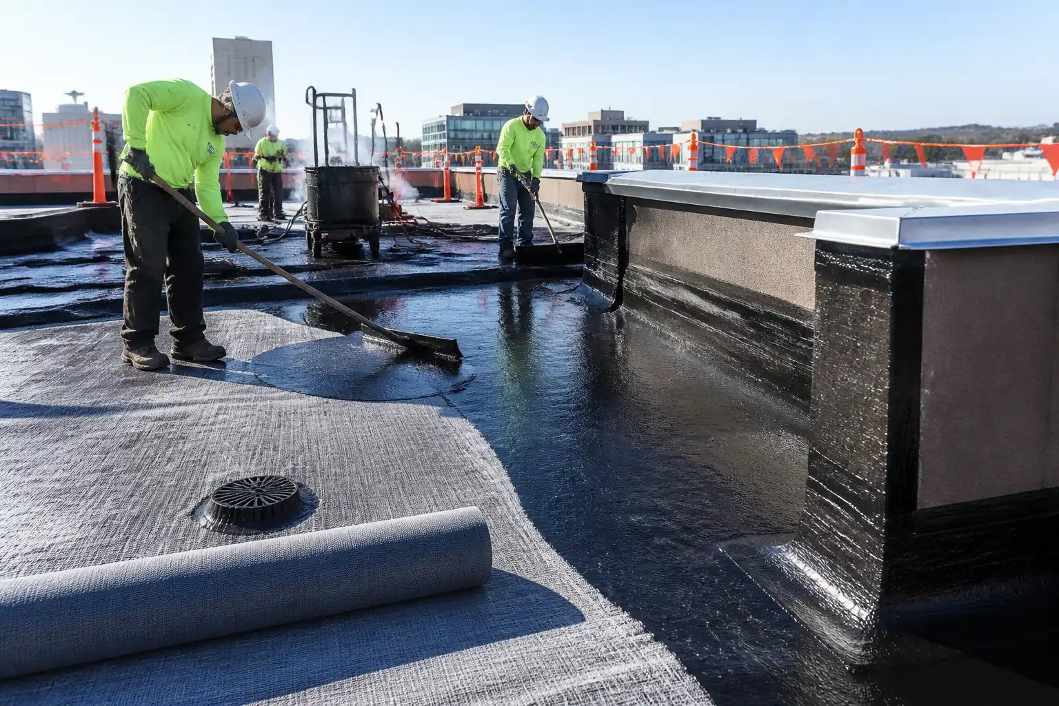
| 5 | Waterproofing-membrane integration with outlet flange | Apply membrane system (bituminous/TPO/PVC/EPDM/liquid) to outlet flange per manufacturer: prime, lay base sheet or single-ply, heat-weld or adhere continuous bond over flange; ensure 150 mm minimum upstand turn-ups at parapets/penetrations [Verify]. Avoid wrinkles/fishmouths. | Waterproofing Applicator | Witness |
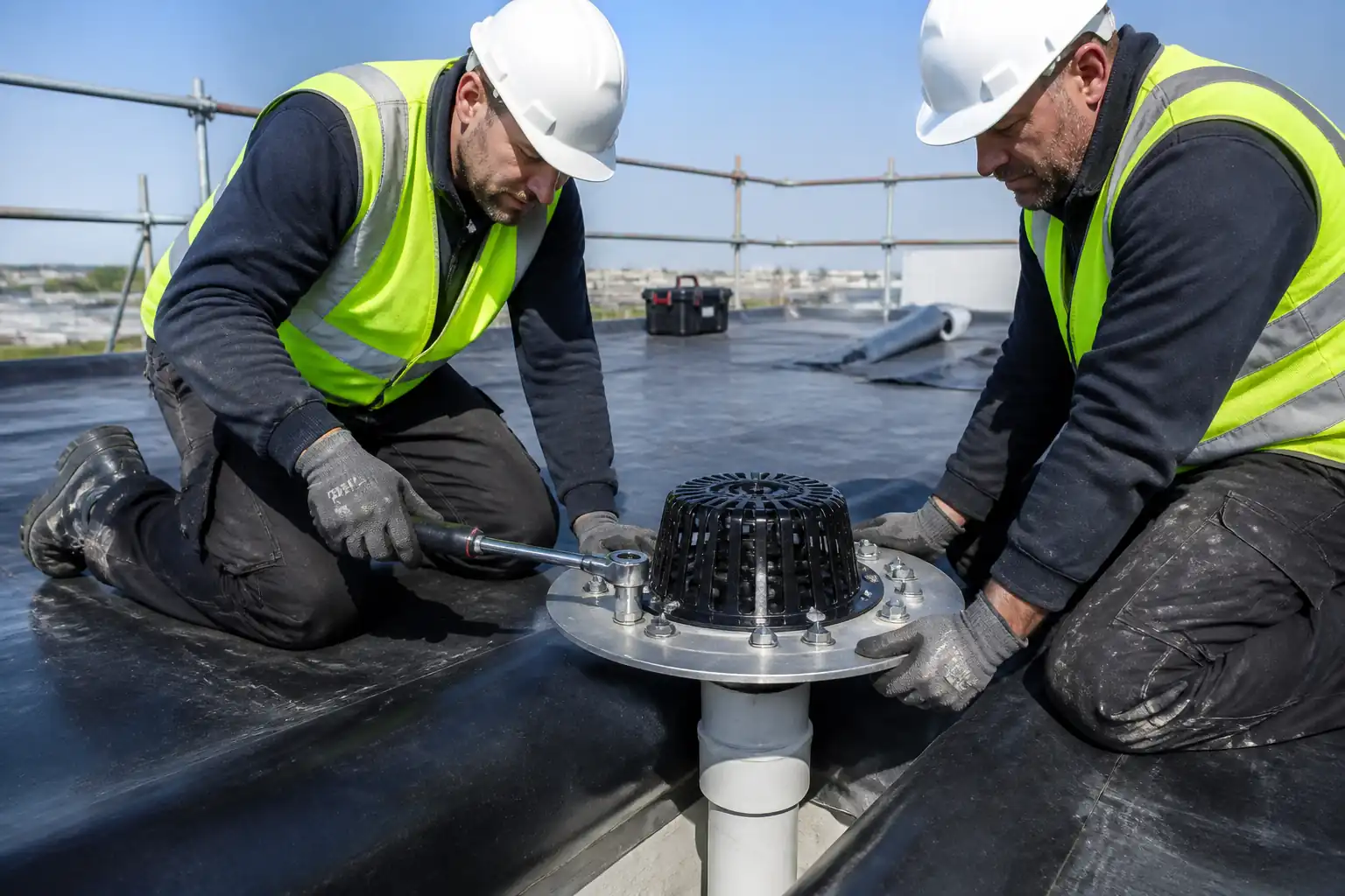
| 6 | Install clamping ring and torque verification | Seat outlet body; place membrane carefully; install clamping ring over membrane; tighten bolts in star pattern using calibrated torque wrench to manufacturer torque (e.g., 8–12 Nm) [Verify]. | Plumber / QA Witness | Hold |
| 7 | Leaf strainer/dome installation | Fit leaf strainer; ensure secure locking without stressing membrane; verify accessibility for maintenance. | Plumber | Surveillance |
| 8 | Install vertical downspouts (uPVC/HDPE) and supports | Install riser clamps at floors; fix brackets/supports. For uPVC, solvent-weld or rubber-ring sockets; for HDPE, butt/electrofusion per ISO 21307. Provide expansion capability (sliding supports/expansion couplers every 4–6 m) [Verify]. | Plumber / Pipefitter | Surveillance |
| 9 | uPVC solvent-weld jointing (if uPVC used) | Dry-fit; mark insertion depth; clean; apply primer then cement; assemble with 1/4 turn; hold for 30–60 s; wipe excess; allow cure per temp (typ. 15–60 min handling; full cure 24 h) [Verify]. | Plumber | Witness (random) |
| 10 | HDPE fusion jointing (if HDPE used) | Scrape oxidation; align; heat to specified temp; fuse with correct pressure/time; cool naturally in clamps; record parameters. | Certified HDPE Welder | Witness |
| 11 | Horizontal collector installation (if any) | Install horizontal runs with continuous fall to outlet; use long-radius bends/swept tees; provide cleanouts at base of stacks, at direction changes >45°, and at intervals per code. | Plumber / Site Engineer | Surveillance |
| 12 | Penetration sealing and firestopping | Install sleeves and seals; apply approved firestopping collars/sealants to required FRL; install acoustic wraps where specified. | Firestopping Contractor | Hold |
| 13 | Pretest checks | Remove debris; verify all caps/cleanouts fitted; confirm clamping ring torque; ensure solvent joints cured; protect finishes. | QA/QC Engineer | Surveillance |
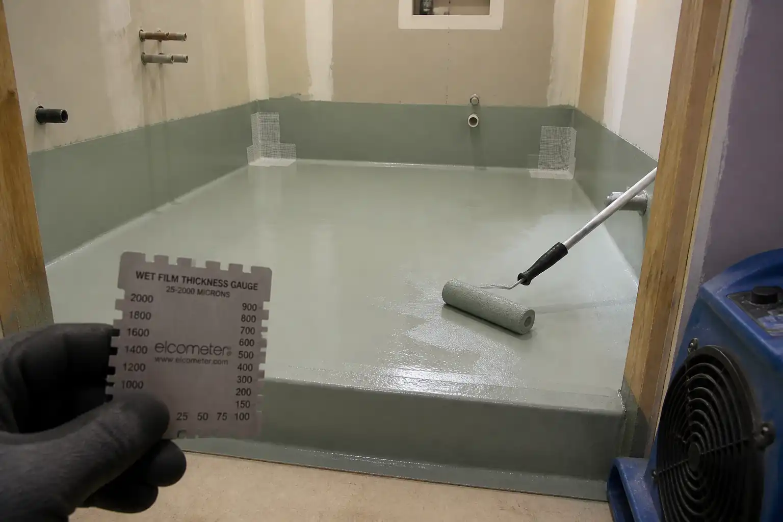
| 14 | Flood testing of outlets and membrane interface | Create temporary dams around each outlet area (e.g., 25–50 mm head). Fill with clean water; maintain for 24 h (or per spec). Inspect underside/rooms below and outlet connections for leakage. | QA/QC with Waterproofing Applicator | Hold/Witness |
| 15 | Sectional water test of downpipes | Plug lowest accessible point; install standpipe; fill to test head (typ. 1.5–3.0 m or to highest joint in section) [Verify]; hold 15 min; inspect all joints/fittings. | QA/QC Engineer | Witness |
| 16 | Functional flow test | Remove plugs; hose-down roof to simulate rainfall; verify free discharge, no ponding, and adequate flow at downpipes. | Site Engineer | Surveillance |
| 17 | Restoration and protection | Remove temporary dams; reinstate finishes; install permanent identification/labels; provide guards if exposed. | Foreman | Surveillance |
| 18 | As-built documentation and handover | Compile records, torque/fusion logs, material certs, test results, and as-built drawings. Submit O&M manuals. | QA/QC Engineer | Review |
Health, Safety and Environment (HSE) – Safety Controls
Key Task-Specific Hazards and Controls
- Hazard: Work at height on roof and at façades/shafts.
- Likely consequence: Falls leading to serious injury or fatality.
- Engineering/procedural control: Install edge protection/guardrails; use full-body harness with double lanyards on certified lifelines; MEWP/scaffold with valid tags; maintain 3:1 rule for ladders only for access; exclude unprotected edges within 2 m.
- Required PPE: Helmet with chin strap, full-body harness EN 361, lanyard EN 355, non-slip safety boots.
- Collective measure: Guardrails, toe boards, access control, rescue plan.
-
Inspection/permit/supervision: Working at Height PTW; daily scaffold/MEWP inspection; competent supervisor present. [Verify per project HSE plan and local regulations]
-
Hazard: Penetrations/core drilling into slabs/walls.
- Likely consequence: Striking rebar/services; structural damage; flying debris.
- Engineering/procedural control: GPR/service scan and permit before drilling; use drill stands with vacuum extraction; set drilling depth stops; exclusion zone and eye/face shields.
- PPE: Safety glasses/face shield, gloves, hearing protection, dust mask (P2/P3 if silica risk).
- Collective measure: Local extraction and wet suppression where applicable; barriers and signage.
-
Inspection/permit/supervision: Penetration PTW; structural approval; tool pre-use checks.
-
Hazard: Hot works (torch-on membranes) and ignition of combustibles.
- Likely consequence: Fire, burns, smoke inhalation.
- Engineering/procedural control: Prefer cold-applied systems where possible; if torch-on, clear combustibles 5 m radius, fire watch during and 60 min after; use flame guards and fire blankets.
- PPE: Flame-resistant gloves, goggles, long sleeves, fire-retardant clothing.
- Collective measure: Fire extinguishers (CO2/dry powder), charged hose nearby.
-
Inspection/permit/supervision: Hot Work Permit; gas leak checks; trained operatives.
-
Hazard: Handling solvents/primers and PVC cement.
- Likely consequence: Dermal/respiratory irritation; flammability.
- Engineering/procedural control: Use low-VOC products; work in well-ventilated areas; keep away from ignition; closed containers; follow SDS.
- PPE: Nitrile gloves, safety glasses, half-mask organic vapor respirator if ventilation inadequate.
- Collective measure: Spill kits and absorbents; decanting trays.
-
Inspection/permit/supervision: SDS available; COSHH assessment; storage in flammable cabinets.
-
Hazard: HDPE fusion equipment (hot surfaces, pinch points, electrical).
- Likely consequence: Burns, electric shock, crush injuries.
- Engineering/procedural control: Guarded plates; insulated leads; lock-off during setup; trained certified welders only; cooling time enforced.
- PPE: Heat-resistant gloves, eye protection, safety footwear.
- Collective measure: Barriers and signage around fusion area.
-
Inspection/permit/supervision: PAT/inspection of equipment; calibration records; supervision by welding lead.
-
Hazard: Manual handling of pipes/fittings and awkward postures.
- Likely consequence: Strains/sprains; dropped objects.
- Engineering/procedural control: Team lifts; use slings, pipe jacks, or MEWP; store pipes on racks; pre-cut lengths.
- PPE: Gloves with grip, safety boots.
- Collective measure: Lift plans for heavy components; exclusion below hoisting.
-
Inspection/permit/supervision: Manual handling briefing; lifting plan approval.
-
Hazard: Confined/service shafts and poor ventilation.
- Likely consequence: Asphyxiation, limited egress.
- Engineering/procedural control: Confined Space PTW where applicable; gas test; forced ventilation; standby watch and rescue kit.
- PPE: Gas detector (if required), harness, headlamp.
- Collective measure: Barricade shaft openings; communication protocol.
-
Inspection/permit/supervision: PTW and gas test logs; trained entrants/attendants.
-
Hazard: Water accumulation during flood testing.
- Likely consequence: Slip hazards; water ingress to lower levels; overloading slab.
- Engineering/procedural control: Temporary bunds sized/secured; control inflow; monitor structural load; continuous supervision; emergency drainage plan.
- PPE: Non-slip boots, gloves.
- Collective measure: Signage and restricted access to wet zones.
-
Inspection/permit/supervision: Test method statement approval; supervisor presence throughout test.
-
Hazard: Noise and dust from drilling/cutting.
- Likely consequence: Hearing loss; respiratory irritation.
- Engineering/procedural control: Select low-noise tools; fit extraction/vacuum; wet methods if compatible.
- PPE: Hearing protection, dust mask (P2/P3 as needed).
- Collective measure: Schedule noisy works in permitted hours.
- Inspection/permit/supervision: Noise monitoring where required.
Environmental Controls
- Water management: Use clean water for flood tests; capture and route discharge to designated drains only after QA sign-off; do not release to unfinished areas. Record volumes and avoid overloading storm network. [Verify per project EMP]
- Chemical management: Store primers/solvents in bunded flammable cabinets; keep lids closed; collect solvent wipes and adhesive containers as hazardous waste; segregate per waste codes.
- Waste and microplastics: Collect plastic swarf and offcuts immediately; prevent entry to rainwater system; use on-tool extraction and site vacuuming.
- Noise and working hours: Comply with local limits and permitted work hours; use acoustic shrouds where possible.
- Dust control: Vacuum extraction on drills; damp wipe surfaces; no dry sweeping.
- Spill prevention: Spill kits within 20 m of workface; treat any adhesive/primer spill as hazardous; report and record.
- Material efficiency: Cut lists to minimize waste; return unused, unopened materials to storage.
- Protection of finished membranes: Use protection boards/walk mats; prohibit solvent contact with incompatible membranes; no storage of sharp/metal items directly on membrane.
QA/QC
Controls and Records
- Material approvals: MIRs with certificates for outlets, pipes, fittings, supports, adhesives, gaskets, and membrane.
- Calibration: Torque wrench and fusion machine calibration certificates; laser level checks.
- Installation checklists: Outlet seating, membrane bonding, clamping ring torque, strainer fit, jointing procedures, support spacing, expansion provision, verticality and slope checks.
- Tolerances/targets:
- Outlet position: ±5 mm; flange flush within 1 mm rocking.
- Clamping torque: As per manufacturer ±10% [Verify].
- Pipe verticality: ≤3 mm per 3 m; horizontal slope ≥1:100; slope tolerance ±0.2% [Verify].
- Support spacing: Vertical 1.8–2.4 m; horizontal 0.8–1.2 m; within 150 mm of fittings [Verify per manufacturer].
- Testing:
- Flood test: 25–50 mm water head; 24 h duration (unless spec differs); acceptance: no leaks, negligible evaporation loss.
- Downpipe sectional water test: Head 1.5–3.0 m (or to highest joint in section); 15 min; acceptance: no visible leakage.
- Functional flow test: No standing water >5 mm after 15 min cessation [Verify].
- Documentation: Torque logs, fusion logs (with parameters), joint logs (cement/primer batch numbers), photos, IRs, NCRs and corrective actions, as-builts, O&M manuals.
- Hold and witness points per ITP.
Attachments
- Approved shop drawings and coordination drawings (roof drainage layouts, sections, details).
- Manufacturer installation manuals: roof drains, membrane systems, solvent cements/primers, HDPE fusion.
- Material approvals: MIRs, certificates of conformity.
- Calibration certificates: torque wrenches, fusion equipment, survey instruments.
- Method-specific checklists: outlet integration, jointing, supports, pretest.
- Test documentation: flood test procedure and reports, downpipe water test certificates, functional flow logs.
- Firestopping approvals/details and inspection records.
- Risk assessments and Permits to Work (Working at Height, Hot Work, Confined Space, Penetration).
- As-built drawings and O&M manuals.
This content is a read-only public reference. Download or customize to get an editable version.
ITP preview
The first inspection activities from the linked ITP for Method Statement: Installation of Roof Rainwater Drainage Outlets and Vertical Downspouts (uPVC/HDPE) with Waterproofing Integration and Flood Testing:
| Activity | Inspection / Test | Acceptance Criteria | Responsibility | Record |
|---|---|---|---|---|
| Material receipt (outlets, pipes, fittings, supports) | Document and visual inspection (MIR) | Conformance to approvals/standards; no damage; certificates available. | QA/QC Engineer | MIR, CoC, IR |
| Setting-out and elevations | Dimensional survey | Outlets positioned within ±5 mm; gradients achievable per design. | Site Engineer / QA/QC | Survey report, IR |
| Substrate preparation at outlets | Surface dryness/cleanliness check | Dry, clean, sound; falls to outlet; no laitance/debris. | Waterproofing Applicator / QA/QC | Checklist, photos |
Showing 3 of 14 inspection activities. View full ITP →
Related Inspection and Test Plan
An Inspection and Test Plan (ITP) is available for Method Statement: Installation of Roof Rainwater Drainage Outlets and Vertical Downspouts (uPVC/HDPE) with Waterproofing Integration and Flood Testing. The ITP defines the inspection activities, acceptance criteria, hold and witness points, responsible parties, and records required to verify the work described in this method statement.
View the Method Statement: Installation of Roof Rainwater Drainage Outlets and Vertical Downspouts (uPVC/HDPE) with Waterproofing Integration and Flood Testing ITP →Frequently asked questions
Continue with related Quollnet resources connected to this method statement.