Method Statement: Liquid-Applied Polyurethane Waterproofing for Internal Wet Areas – Method Statement
AI-assisted method statement with matching ITP, PDF download, and Excel export.
More than a static template
Unlike a downloadable Word or PDF template, this method statement is an AI-assisted editable starting point connected directly to a matching Inspection and Test Plan. Every section is structured, project-adaptable, and ready to export.
- AI-assisted drafting — Customize every section with AI for your specific project scope.
- Linked ITP — A matching inspection and test plan is generated alongside the method statement.
- Multiple export formats — Download as a formatted PDF or editable Excel spreadsheet.
- Editable starting point, not a final document — Review, verify, and adjust all content against your project requirements before use.
Static template vs. Quollnet workflow
| Feature | Static template | Quollnet |
|---|---|---|
| Project-specific content | Manual fill-in required | AI-assisted customization |
| Linked ITP | Separate document, no link | Matching ITP included |
| Export formats | Usually PDF only | PDF and Excel |
| Structured sections | Free-form layout | 13 standardized sections |
| Saved to your account | Local file only | Cloud-saved, reusable |
| Content accuracy | You verify everything | AI-assisted, you still verify |
| Cost | Often free but time-intensive | Free to customize and download |
What you can customize
When you save this method statement to your account, every section becomes editable. The following 13 sections are included:
- Scope — Defines the activity and its boundaries.
- References — Standards, specifications, and drawings.
- Responsibilities — Roles and accountabilities.
- Resources — Labour, plant, and equipment summary.
- Materials — Materials and compliance requirements.
- Equipment — Tools and equipment details.
- Prerequisites — Hold points and pre-conditions.
- Method sequence — Step-by-step construction sequence.
- Safety controls — HSE risk controls and PPE.
- Environmental controls — Environmental mitigation measures.
- QA/QC — Quality inspection and test requirements.
- ITP — Inspection and Test Plan table (has its own page).
- Attachments — Referenced drawings and documentation.
Why this method statement is used
This method statement is used to define and communicate the approved procedure for carrying out method statement: liquid-applied polyurethane waterproofing for internal wet areas on site. It ensures the work is planned in advance, the correct resources and controls are in place, and all personnel understand responsibilities, sequence, quality requirements, and safety controls before work begins. It aligns site execution with the documented scope and acceptance expectations.
Who uses this method statement
This method statement is used by contractors, site supervisors, project engineers, QA/QC engineers, HSE officers, consultants, and client representatives. It serves as a shared reference for planning, execution, supervision, inspection, and approval of the activity on site.
When it is prepared and submitted
The method statement is prepared before the work activity starts and submitted as part of the pre-construction documentation package for review and approval.
Who reviews or approves it
The method statement is usually submitted to the client representative, consultant, resident engineer, or project management consultant for review and approval before the work commences.
Important approval note
This method statement is an AI-assisted editable starting point, not a pre-approved document. Before use on any project, all content must be reviewed and approved by the relevant parties (superintendent, principal contractor, or client representative) in accordance with your contract and project quality plan.
For example: if your specification requires a departure from a referenced standard, that departure must be documented and approved separately — this method statement will not capture that automatically. Always verify against your applicable drawings, specifications, and regulatory requirements.
Method statement content
Scope
Work Summary
- Supply and install liquid-applied polyurethane (PU) waterproofing membrane systems to internal wet areas such as bathrooms, showers, toilets, pantries, laundries, and kitchens.
- Includes substrate preparation, moisture testing, priming, elastomeric fillet at wall–floor junctions, reinforcement at stress points/penetrations, multi-coat PU application to achieve specified dry film thickness (DFT), detailing to upstands/thresholds, curing, 24-hour flood test, rectification, and handover for tiling/protection.
Areas Included
- Floor areas with upturns to surrounding walls/partitions, shower recesses, around drains, pipe penetrations, thresholds, and wet walls as indicated on drawings.
Exclusions
- Structural repairs beyond minor crack/spall repairs.
- Final floor/wall finishes and screeds unless noted.
Key Performance Targets
- Slope to drain prior to membrane: typically 1:80 to 1:60 toward outlets [Verify per project specifications].
- Minimum DFT: typically ≥ 1.2 mm overall, uniform, pinhole-free [Verify per product datasheet].
- Flood test: 24 hours minimum, no leakage, no unacceptable water loss.
- Adhesion to substrate (if specified): pull-off ≥ 0.7 MPa, predominantly cohesive failure [Verify per project specifications].
References
| Document Type | Reference / Number | Revision | Notes |
|---|---|---|---|
| BS EN 14891 | Use when tiling over membrane is specified. | ||
| EAD 030437-00-0503 | For CE-marked systems in wet rooms. | ||
| ASTM C836/C836M | Benchmark properties for PU membranes (tensile, elongation, waterproofing). | ||
| ASTM D4541 | For adhesion verification of membrane/primer as specified. | ||
| ICRI 310.2R | Target CSP 1–3 for PU membranes (verify with manufacturer). | ||
| ASTM F2170 | Typical acceptance ≤ 75–85% RH for PU membranes [Verify per datasheet]. | ||
| ASTM F1869 | Typical acceptance ≤ 3–5 lb/1000 ft²/24 h [Verify per datasheet]. | ||
| ANSI A118.10 | If tile setting directly over membrane is specified. | ||
| BS 5385-4 | Contains guidance on wet areas and waterproof backgrounds. | ||
| ISO 45001, ISO 14001, ISO 9001 | For overall management frameworks. |
Responsibilities
| Role | Responsibility | Name / Party |
|---|---|---|
| Project Manager | Main Contractor | |
| Site Engineer / Construction Manager | Main Contractor | |
| QA/QC Engineer | Main Contractor | |
| HSE Officer | Main Contractor | |
| Approved Waterproofing Applicator (Certified) | Specialist Subcontractor | |
| Manufacturer’s Representative / Independent Tester | Manufacturer / Third Party | |
| Engineer/Consultant | Client/Consultant |
Resources
| Resource Type | Description | Quantity | Remarks |
|---|---|---|---|
| Labor | Certified in PU membrane installation; ratio 1 lead + 2 operatives per 150–200 m²/week [Verify per productivity]. | As scheduled | |
| Labor | Surface prep, masking, mixing assistance, material handling. | As required | |
| Staff | WFT/DFT/readings, moisture tests, records, ITP checklists. | 1 per work front | |
| Staff | Permits, monitoring air quality/ventilation, chemical safety, housekeeping audits. | Shared |
Materials
| Material | Specification / Grade | Quantity | Remarks |
|---|---|---|---|
| Polyurethane/Epoxy Primer | Compatible with EN 14891/ASTM C836 systems; VOC per local regs [Verify]. | ||
| PU Liquid Membrane | Meets EN 14891 or ASTM C836 performance; elongation ≥ 200% typical [Verify]. | ||
| Polyester Reinforcement | Compatible with PU system per manufacturer. | ||
| PU/Silicone Sealant + Backer Rod | Meets ISO 11600 class (typical) [Verify]. | ||
| Repair Mortar/Epoxy | ICRI-compatible; manufacturer-approved. | ||
| Consumables | Project-specific [Verify]. |
Equipment
| Equipment | Capacity / Type | Quantity | Inspection Required |
|---|---|---|---|
| Grinders + Vacuums | |||
| Electric Mixer | >800 W | ||
| Hand Tools | |||
| WFT/DFT Gauges | |||
| Moisture/Climate Instruments | |||
| Pull-off Tester | 0–3 MPa | ||
| Flood Test Kit | |||
| HSE Equipment |
Prerequisites
Approvals and Submissions
- Method Statement and ITP approved by Engineer/Consultant prior to works.
- Manufacturer’s datasheets, SDS, and compatibility statements submitted for primer, membrane, sealant, and reinforcement.
- Applicator qualifications/approval letter and toolbox talk records available.
Site and Substrate Readiness
- Plumbing pressure tests for concealed services in wet areas completed and passed prior to membrane works [Verify per project specifications].
- Substrate age: cement-sand screed typically ≥ 7 days (rapid-set) or ≥ 28 days (standard) before PU application unless moisture barrier is used [Verify datasheet/spec].
- Surface finish: sound, clean, dry, free from laitance, dust, oils, curing agents, and contaminants; repairs completed and cured.
- Level and falls: confirm slopes to drain 1:80–1:60; tolerances typically ±3 mm under 2 m straightedge [Verify per spec].
- Movement/control joints identified and bond-breaker details agreed.
Environmental Conditions
- Ambient/substrate temperature typically 5–35°C; RH < 85%; dew point: substrate temperature ≥ 3°C above dew point to prevent condensation [Verify datasheet].
- Ensure adequate mechanical ventilation for enclosed rooms; no ignition sources near solvent-based primers [Verify per project HSE plan and local regulations].
Permits and Controls
- PTW for chemical use/solvent use and flood test authorization in occupied buildings.
- Electrical tools PAT-checked; RCDs in wet areas.
- Adjacent finishes and drains protected/masked.
Mock-Up
- Execute a mock-up area (e.g., 1–2 m²) including a corner, a penetration, and a drain. Demonstrate WFT/DFT, reinforcement, and cure. Obtain written approval.
Method Sequence
| Step | Activity | Description | Responsibility | Inspection / Hold Point |
|---|---|---|---|---|
| 1 | Verification and Pre-Clean | Confirm approvals, verify substrate falls and integrity. Mechanically abrade to achieve CSP 1–3; remove laitance. Vacuum to HEPA standard. Degrease localized contamination with solvent cleaner as approved. | Site Engineer / Applicator | Visual cleanliness, CSP profile check |
| 2 | Moisture Assessment | Test substrate moisture by ASTM F2170 (RH probes) and/or ASTM F1869 (MVER) as required. If above limits, install moisture-tolerant epoxy primer/vapor barrier per manufacturer. | QA/QC Engineer | Moisture readings |
| 3 | Crack and Defect Repair | Chase cracks >0.3 mm, fill with epoxy or repair mortar. Remove loose edges, fill voids; reprofile to smooth transitions; allow to cure. | Applicator | Visual; tapping |
| 4 | Priming | Mix/apply primer uniformly by roller/brush as per datasheet; avoid ponding. Back-roll to ensure penetration. Allow to dry within recoat window. | Applicator | Coverage and uniformity |
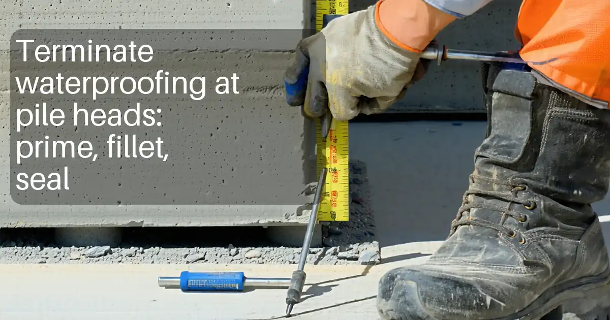
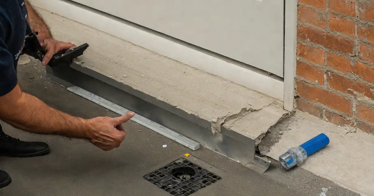
| 5 | Fillet Formation at Wall–Floor Junctions | Apply elastomeric sealant with backer rod if needed; tool to continuous 20–25 mm radius fillet. Allow skin/cure per sealant TDS. | Applicator | Continuity of fillet |
| 6 | Detail Reinforcement | Embed reinforcement fabric into a wet coat around corners, fillets, upstands, cracks, and penetrations; lap ≥50 mm; smooth out wrinkles; saturate with membrane. | Applicator | Visual check of embedment and laps |
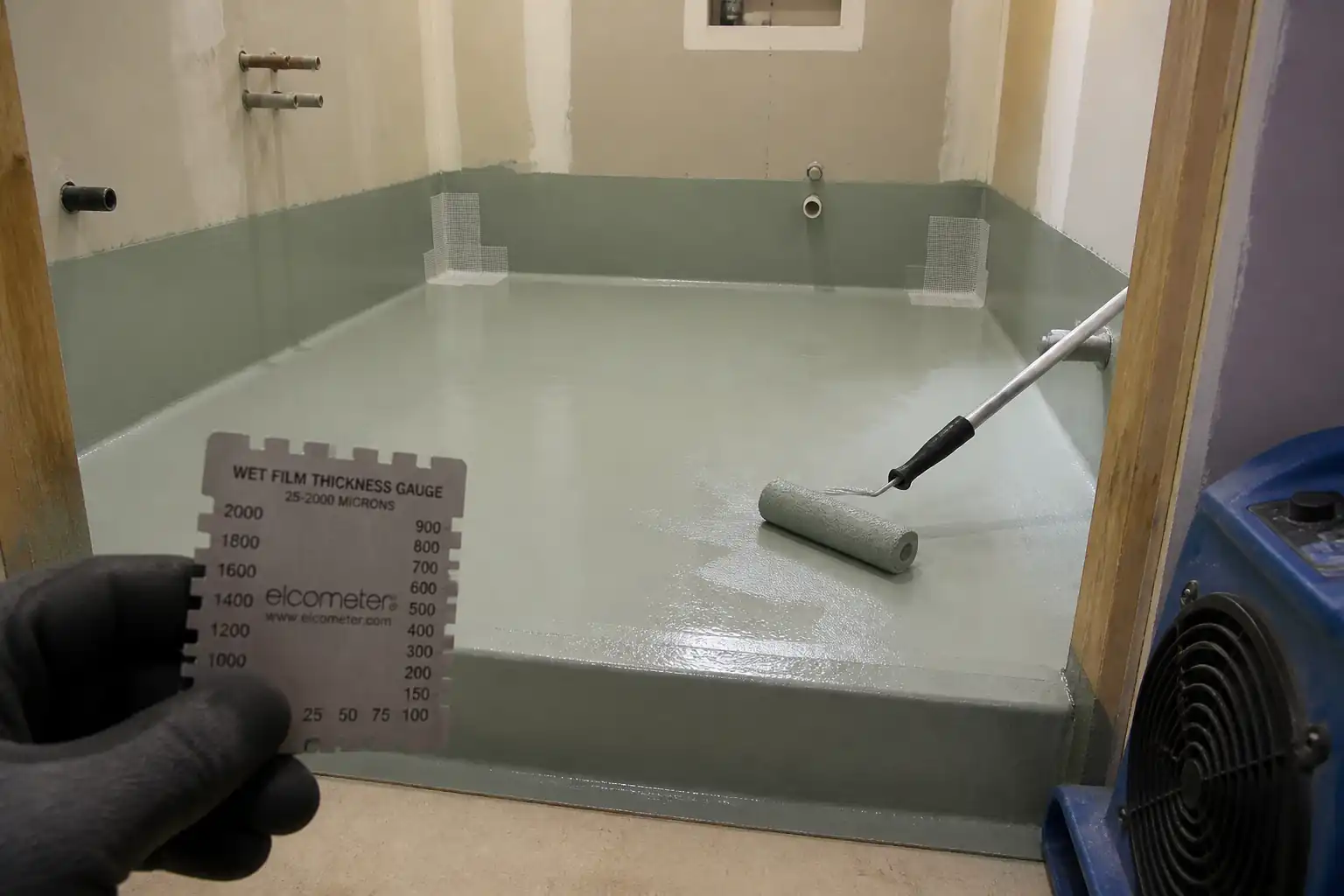
| 7 | First PU Coat (Base) | Mix as per TDS. Apply by roller/squeegee to achieve target WFT. Work away from exit. Avoid pinholes; stripe coat details first. | Applicator | WFT checks per zone |
| 8 | Intercoat Cure and Inspection | Allow to cure to tack-free. Inspect for defects; repair pinholes by spot application. Ensure within recoat window. | Applicator / QA | Tack-free; visual defects |
| 9 | Second PU Coat (Cross Direction) | Apply at right angles to first to achieve cumulative target DFT. Reinforce around drains/penetrations if not completed. | Applicator | WFT checks; coverage at upstands |
| 10 | DFT Verification | After full cure, verify DFT using comb gauges at representative points or calculate from total WFT and product solids; map readings on plan. | QA/QC Engineer | Thickness mapping |
| 11 | Cure to Flood-Test Readiness | Allow final coat to cure to manufacturer’s stated immersion-ready time. | Applicator / QA | Cure status vs. TDS |
| 12 | 24-Hour Flood Test | Install temporary bunds (≥25 mm). Plug drains. Fill to min 25 mm water depth. Mark reference. Maintain for ≥24 h; inspect below/adjacent spaces for leaks. | Site Engineer / QA | Leak observation; water level |
| 13 | Defect Rectification (If Any) | Drain water, dry area, mark defects, abrade area, re-prime if required, re-apply membrane. Allow cure and re-test. | Applicator | Repaired area checks |
| 14 | Optional Adhesion Testing | Perform pull-off adhesion tests at agreed locations after cure. Patch test spots afterward with membrane. | Third Party / QA | Dolly adhesion values |
| 15 | Protection and Handover | Remove bunds/masking. Protect membrane with geotextile/boards if traffic expected. Handover with records for tiling release. | Site Engineer / Applicator | Protection integrity |
Health, Safety and Environment (HSE) – Task-Specific Safety Controls
Risk Assessment Controls
- Hazard: Solvent vapors from primers (flammable, irritant)
- Likely consequence: Fire/explosion; respiratory irritation; CNS effects
- Engineering/procedural control: Use low-VOC/solvent-free where possible; eliminate ignition sources; provide forced ventilation achieving ≥6 air changes/hour; decant in well-ventilated areas; use intrinsically safe lighting where required
- Required PPE: Organic vapor respirator (A2 filters) where needed, safety glasses, nitrile gloves, long sleeves
- Collective preventive measure: No Hot Work within 10 m; flammable cabinet for storage; spill kits ready
-
Inspection/permit/supervision: Chemical use PTW; gas/vapor checks if confined; SDS on site; HSE walkdowns [Verify per project HSE plan and local regulations]
-
Hazard: Isocyanate exposure from PU products
- Likely consequence: Respiratory sensitization/asthma; dermal sensitization
- Engineering/procedural control: Avoid spraying; apply by roller/squeegee; local exhaust ventilation; restrict access; training on isocyanate handling
- Required PPE: Half-mask respirator with A2/P3 filters, nitrile gloves (0.4 mm), coveralls, eye protection
- Collective preventive measure: Signage “Isocyanates in Use”; emergency eyewash; medical surveillance per policy
-
Inspection/permit/supervision: HSE monitoring; verify SDS and exposure limits; supervision during mixing
-
Hazard: Silica dust during grinding/abrading
- Likely consequence: Respiratory illness; eye injury
- Engineering/procedural control: Tools with shrouds and HEPA vacuums; wet suppression where safe; isolate area
- Required PPE: P3 disposable respirator or half-mask with P3, safety goggles
- Collective preventive measure: Enclosure/curtains; housekeeping plan
-
Inspection/permit/supervision: Equipment inspection; dust monitoring if required
-
Hazard: Slips on wet membrane or flood test water
- Likely consequence: Falls, sprains
- Engineering/procedural control: Sequence to exit; restrict access; non-slip overshoes; barriers and signage; pump/absorb spills immediately
- Required PPE: Non-slip safety footwear
- Collective preventive measure: Temporary edge/door bunds with visible marking
-
Inspection/permit/supervision: Supervisor to maintain exclusion zone
-
Hazard: Manual handling of 15–25 kg pails
- Likely consequence: Strains, musculoskeletal injuries
- Engineering/procedural control: Use trolleys; team lifts; decant into smaller containers
- Required PPE: Gloves with grip, safety footwear
- Collective preventive measure: Material staging near workface
-
Inspection/permit/supervision: Manual handling training and observation
-
Hazard: Electrical hazards in wet environments
- Likely consequence: Electric shock
- Engineering/procedural control: Use 110V tools or RCD-protected circuits; keep cords elevated; no live cords during flood tests
- Required PPE: Dry-hand procedures; insulated gloves when needed
- Collective preventive measure: Lockout/tagout of outlets near flood test area
-
Inspection/permit/supervision: Electrical PTW/LOTO as required; PAT test records
-
Hazard: Ingress to lower floors during flood test
- Likely consequence: Property damage; mold risk
- Engineering/procedural control: Pre-inspect below ceiling; establish bunds ≥25 mm; continuous monitoring first 2 hours; emergency drain plan
- Required PPE: As standard
- Collective preventive measure: Notify occupants; place drip trays below historical leak points
-
Inspection/permit/supervision: Flood test PTW; consultant witness; log start/finish levels
-
Hazard: Fire from solvent storage
- Likely consequence: Burns; facility damage
- Engineering/procedural control: Store in ventilated, bunded, locked flammable stores; decant minimum quantities only
- Required PPE: Standard + fire-resistant gloves if handling large volumes
- Collective preventive measure: Foam/CO2 extinguishers; no-smoking zone
- Inspection/permit/supervision: Weekly store inspection; extinguisher checks
Environmental Controls
- VOC and Odor Management: Prefer low-VOC products. Use mechanical ventilation and schedule work off-hours where sensitive receptors exist. Monitor odor complaints and adjust airflow.
- Waste Management: Collect empty pails, roller covers, masking waste in labeled containers. Triple-rinse if required by supplier; otherwise treat as hazardous waste if solvent residues remain. Maintain waste transfer notes [Verify per local regulations].
- Spill Prevention: Secondary containment for liquids; spill kits at mixing points; train crew on immediate containment and reporting.
- Water Use and Discharge: Flood test water must be drained via sanitary systems only; do not discharge to storm drains. Prevent silt/paint solids; use strainer at drains.
- Noise/Dust: Use low-noise equipment; dust extraction during grinding; maintain doors closed to contain dust; clean with HEPA vacuums (no dry sweeping).
- Material Storage: Keep products between 10–30°C, off the floor, out of direct sunlight; segregate incompatible chemicals.
- Energy/Carbon: Optimize batch mixing to reduce waste; use LED task lighting and high-efficiency fans.
- Documentation: Keep SDS, batch logs, and waste manifests; include environmental inspection checklists.
Quality Assurance / Quality Control
Controls and Records
- Calibrations: WFT/DFT gauges and pull-off testers calibrated within the last 6 months [Verify per QA plan].
- Batch Traceability: Record product names, batch/lot numbers, manufacture/expiry dates, and mixing ratios on Batch Log.
- Environmental Records: Record ambient and substrate temperature, RH, and dew point each shift.
- Testing Frequencies:
- Moisture tests: Minimum 1 per room (≤25 m²) and 1 per additional 50 m² or part thereof.
- WFT: Minimum 3 readings per room per coat, plus one per 10 m² for larger rooms.
- DFT: Minimum 1 location per 10 m²; more at edges/penetrations.
- Adhesion (if specified): Minimum 3 tests per area or 1 per 200 m², whichever is greater.
- Flood test: 100% of wet areas.
- Acceptance Criteria:
- Substrate falls: 1:80–1:60 toward drains; tolerance ±3 mm under 2 m straightedge [Verify].
- Moisture: RH ≤ 75–85% or MVER ≤ 3–5 lb/1000 ft²/24 h as product allows [Verify].
- Film thickness: Overall DFT ≥ specified (typ. ≥1.2 mm) with no local thin spot < 90% of specified.
- Integrity: No pinholes, blisters, or fish-mouths; full coverage at corners and penetrations.
- Flood test: No leakage; water loss ≤ 2 mm after evaporation compensation.
- Adhesion: ≥ 0.7 MPa (or per spec); cohesive failure preferred.
- Nonconformance: Mark defects, raise NCR, correct by abrading, re-priming if needed, re-coating, and re-testing.
- Handover Dossier: Approved ITP, WFT/DFT logs and maps, moisture test reports, flood test certificates, batch logs, MSDS/SDS, calibration certificates, as-built marked-up plans.
Attachments
- Manufacturer Technical Data Sheets (TDS) and Safety Data Sheets (SDS) for primer, membrane, sealant, and reinforcement.
- Pre-application checklist (substrate, moisture, environmental conditions).
- WFT/DFT logging templates and example DFT map.
- Flood test certificate template and permit to work (PTW) forms.
- Equipment calibration certificates (WFT/DFT gauges, pull-off tester).
- Mock-up approval record and photo documentation.
- Nonconformance/Corrective Action Report (NCR/CAR) templates.
This content is a read-only public reference. Download or customize to get an editable version.
ITP preview
The first inspection activities from the linked ITP for Method Statement: Liquid-Applied Polyurethane Waterproofing for Internal Wet Areas:
| Activity | Inspection / Test | Acceptance Criteria | Responsibility | Record |
|---|---|---|---|---|
| Substrate condition and falls check | Straightedge tolerance; visual soundness; slope measurement | Falls 1:80–1:60; tolerance ±3 mm under 2 m; substrate sound, clean | Site Engineer / QA | Pre-application checklist; photos |
| Moisture testing | ASTM F2170 (RH) and/or F1869 (MVER) | RH ≤ 75–85% or MVER ≤ 3–5 lb/1000 ft²/24 h [Verify] | QA/QC Engineer | Moisture test report |
| Priming | Visual coverage; WFT if specified | Uniform film; no ponding; tack-free before next step | Applicator / QA | Primer inspection record; batch log |
Showing 3 of 13 inspection activities. View full ITP →
Related Inspection and Test Plan
An Inspection and Test Plan (ITP) is available for Method Statement: Liquid-Applied Polyurethane Waterproofing for Internal Wet Areas. The ITP defines the inspection activities, acceptance criteria, hold and witness points, responsible parties, and records required to verify the work described in this method statement.
View the Method Statement: Liquid-Applied Polyurethane Waterproofing for Internal Wet Areas ITP →Frequently asked questions
Continue with related Quollnet resources connected to this method statement.