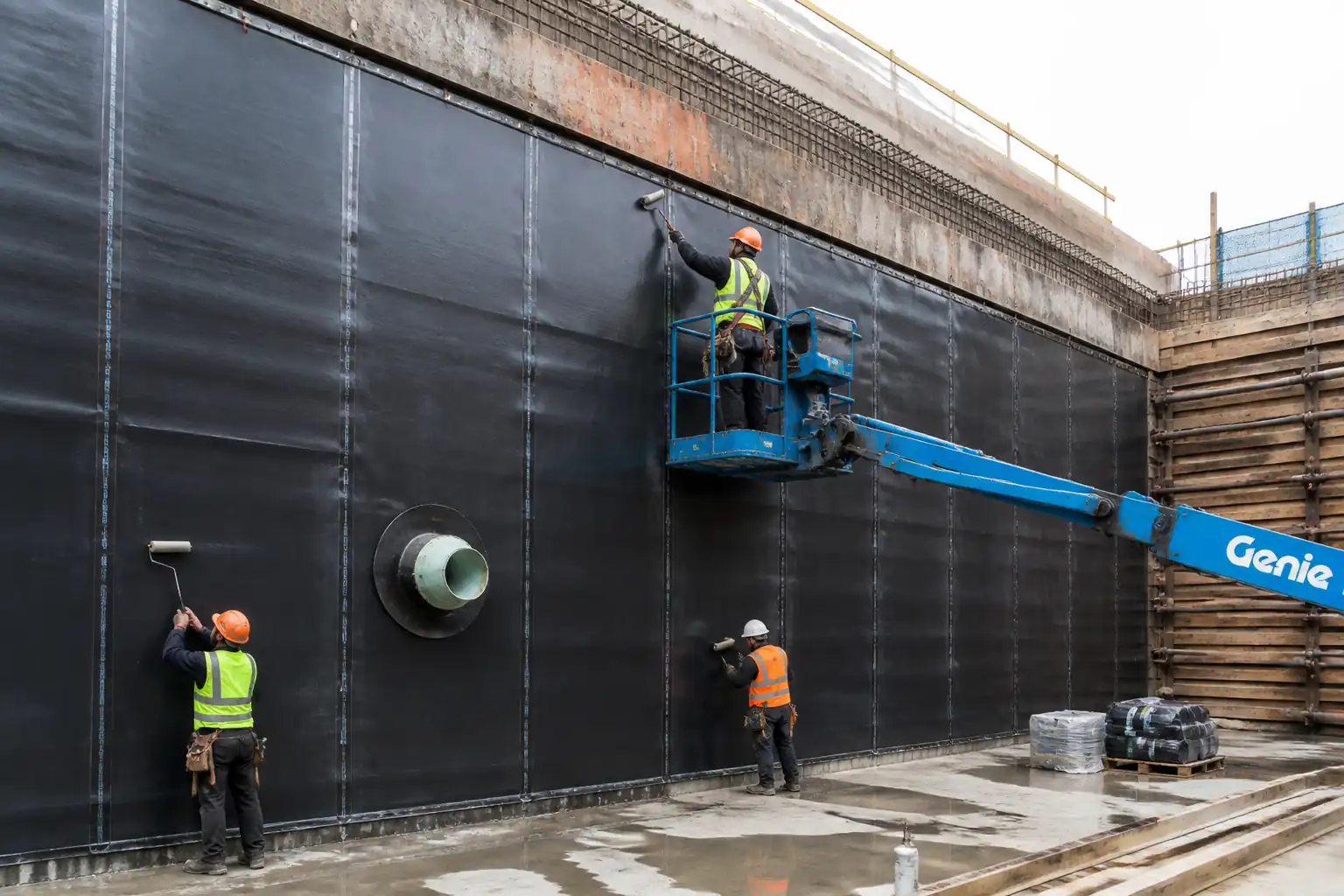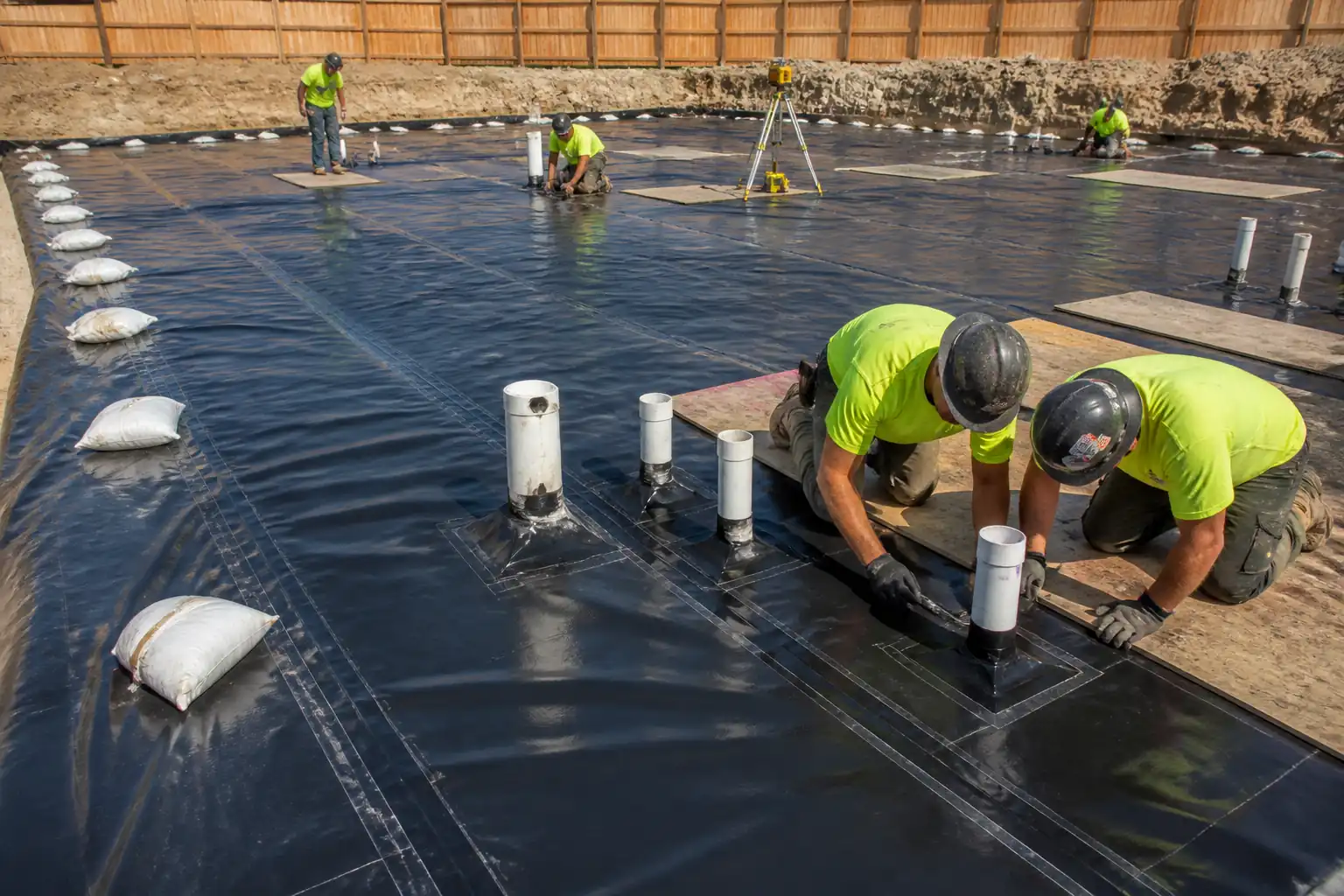
Inspection and Test Plan for Method Statement: Installation of Continuous Vapor Control Layers and Air-Barrier Membranes
AI-assisted inspection and test plan connected to a method statement, with PDF and Excel export.
More than a static template
Unlike a downloadable Word or PDF template, this ITP is an AI-assisted editable starting point directly connected to its method statement. Every inspection activity, hold point, and acceptance criterion is structured and ready to adapt to your project.
- AI-assisted customization — Tailor inspection activities and acceptance criteria to your specific project scope.
- Linked method statement — This ITP is connected to the corresponding method statement describing the work sequence.
- Multiple export formats — Download as a formatted PDF or editable Excel spreadsheet.
- Editable starting point, not a final document — Review and verify all content against your project specifications and standards before use.
What you can customize
When you save this ITP to your account, every inspection row becomes editable. You can add, remove, or modify:
- Inspection activity — Description of what is being inspected.
- Inspection type — Hold point (H), Witness point (W), Review (R), or Monitor (M).
- Responsibility — Contractor, subcontractor, engineer, or client.
- Frequency — How often the inspection occurs.
- Acceptance criteria — Referenced standard or specification requirement.
- Records — Forms, test reports, or checklists required as evidence.
Why this ITP is used
To ensure airtightness and vapor control performance through defined inspections, tests, and records that verify compliance with project requirements.
Who uses this inspection and test plan
Site Engineers, QA/QC Engineers, Specialist Installers, HSE Officers, and Independent Testing Agencies.
When this ITP is prepared and submitted
From material delivery through installation, intermediate testing, and final completion before handover.
Who receives or approves this ITP
Consultant/Client for approval and witnessing at hold points.
Inspection scope
Material approvals, substrate verification, membrane placement, lap and perimeter sealing, penetrations, and blower door tests (intermediate and final).
Typical hold, witness, and review points
H1 Substrate approval; H2 First-of-kind detail; H3 Intermediate blower door; H4 Final blower door.
Typical inspection records
MIRs, ITRs, peel test logs, calibration certificates, photo records, blower door reports, NCR/CAR logs.
Important approval note
This ITP is an AI-assisted editable starting point, not a pre-approved document. Before use on any project, all inspection activities, hold points, and acceptance criteria must be reviewed and approved by the relevant parties (superintendent, principal contractor, or client representative) in accordance with your contract and project quality plan.
Always verify acceptance criteria against your applicable drawings, specifications, and regulatory requirements. Hold points must be confirmed with the relevant authority before work proceeds past that point.
Inspection and test plan
| Activity | Inspection / Test | Acceptance Criteria | Responsibility | Record |
|---|---|---|---|---|
| Material delivery and approval | Verify CE/DoP/CoC; batch numbers; SDS/TDS present | Materials as per approved submittals; undamaged packaging | QA/QC Engineer | MIR; delivery notes |
| Substrate inspection (H1) | Visual; timber MC; concrete RH | Clean, sound, dry; MC ≤ 16%; RH ≤ 75% [Verify] | Site Engineer / QA/QC | ITR; moisture logs |
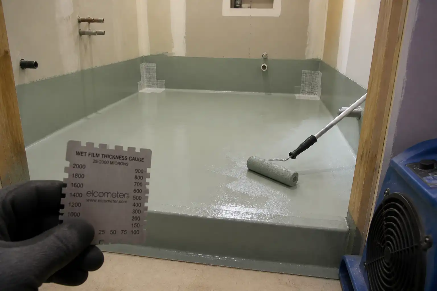
| Primer application (if used) | Check coverage and tack | Uniform film; within open time; adequate ventilation | Installer / QA/QC | ITR; daily report |
| Membrane placement and fixing | Alignment; staple zones; deflection allowance | Wrinkle-free; staples only in lap zones and covered | Installer / QA/QC | ITR; photos |
| Lap joint sealing (H2 first-of-kind) | Lap width; roller pressure; peel test after 24 h | Lap ≥ 100–150 mm; adhesion ≥ 1 N/mm or cohesive failure [Verify] | QA/QC (Witness) / Installer | ITR; peel test log; photos |
| Perimeter/interface sealing | Bond width; continuity at corners | Bond ≥ 25 mm; no discontinuities | Installer / QA/QC | ITR; photos |
| Window bracket detailing | Visual; smoke pencil (if available) | Continuous seal around brackets; layered tapes | Installer / QA/QC | ITR; photos |
| Electrical boxes and penetrations | Visual; collar fit; sealant set | Airtight boxes/collars installed; all cuts sealed | Installer / MEP / QA/QC | ITR; photos |
| Intermediate blower door test (H3) | ISO 9972 Method B; smoke/IR leak check | n50 ≤ project target; leaks logged for remediation | Testing Agency / QA/QC | Interim test report; leak list |
| Remedial sealing and verification | Spot retest; smoke | No detectable leaks at repaired areas | Installer / QA/QC | Punch list close-out |
| Final blower door test (H4) | ISO 9972 Method A (as-built) | n50 ≤ project target [Verify] | Testing Agency (Witness by Client/Consultant) | Final test report; calibration certs |
This table is a read-only public reference. Download the PDF or Excel version, or customize this ITP to edit it for your project.
Frequently asked questions
Related method statement
This Inspection and Test Plan is associated with the Method Statement: Installation of Continuous Vapor Control Layers and Air-Barrier Membranes method statement, which describes the step-by-step construction sequence, resources, materials, equipment, safety controls, and environmental controls for this activity.
View the Method Statement: Installation of Continuous Vapor Control Layers and Air-Barrier Membranes method statement →Continue with related inspection, method statement, article, and checklist resources.