Method Statement: Pre-applied HDPE Blindside Waterproofing for Deep Basements (Shotcrete/Shoring) – Method Statement
AI-assisted method statement with matching ITP, PDF download, and Excel export.
More than a static template
Unlike a downloadable Word or PDF template, this method statement is an AI-assisted editable starting point connected directly to a matching Inspection and Test Plan. Every section is structured, project-adaptable, and ready to export.
- AI-assisted drafting — Customize every section with AI for your specific project scope.
- Linked ITP — A matching inspection and test plan is generated alongside the method statement.
- Multiple export formats — Download as a formatted PDF or editable Excel spreadsheet.
- Editable starting point, not a final document — Review, verify, and adjust all content against your project requirements before use.
Static template vs. Quollnet workflow
| Feature | Static template | Quollnet |
|---|---|---|
| Project-specific content | Manual fill-in required | AI-assisted customization |
| Linked ITP | Separate document, no link | Matching ITP included |
| Export formats | Usually PDF only | PDF and Excel |
| Structured sections | Free-form layout | 13 standardized sections |
| Saved to your account | Local file only | Cloud-saved, reusable |
| Content accuracy | You verify everything | AI-assisted, you still verify |
| Cost | Often free but time-intensive | Free to customize and download |
What you can customize
When you save this method statement to your account, every section becomes editable. The following 13 sections are included:
- Scope — Defines the activity and its boundaries.
- References — Standards, specifications, and drawings.
- Responsibilities — Roles and accountabilities.
- Resources — Labour, plant, and equipment summary.
- Materials — Materials and compliance requirements.
- Equipment — Tools and equipment details.
- Prerequisites — Hold points and pre-conditions.
- Method sequence — Step-by-step construction sequence.
- Safety controls — HSE risk controls and PPE.
- Environmental controls — Environmental mitigation measures.
- QA/QC — Quality inspection and test requirements.
- ITP — Inspection and Test Plan table (has its own page).
- Attachments — Referenced drawings and documentation.
Why this method statement is used
This method statement is used to define and communicate the approved procedure for carrying out method statement: pre-applied hdpe blindside waterproofing for deep basements (shotcrete/shoring) on site. It ensures the work is planned in advance, the correct resources and controls are in place, and all personnel understand responsibilities, sequence, quality requirements, and safety controls before work begins. It aligns site execution with the documented scope and acceptance expectations.
Who uses this method statement
This method statement is used by contractors, site supervisors, project engineers, QA/QC engineers, HSE officers, consultants, and client representatives. It serves as a shared reference for planning, execution, supervision, inspection, and approval of the activity on site.
When it is prepared and submitted
The method statement is prepared before the work activity starts and submitted as part of the pre-construction documentation package for review and approval.
Who reviews or approves it
The method statement is usually submitted to the client representative, consultant, resident engineer, or project management consultant for review and approval before the work commences.
Important approval note
This method statement is an AI-assisted editable starting point, not a pre-approved document. Before use on any project, all content must be reviewed and approved by the relevant parties (superintendent, principal contractor, or client representative) in accordance with your contract and project quality plan.
For example: if your specification requires a departure from a referenced standard, that departure must be documented and approved separately — this method statement will not capture that automatically. Always verify against your applicable drawings, specifications, and regulatory requirements.
Method statement content
Scope
Description
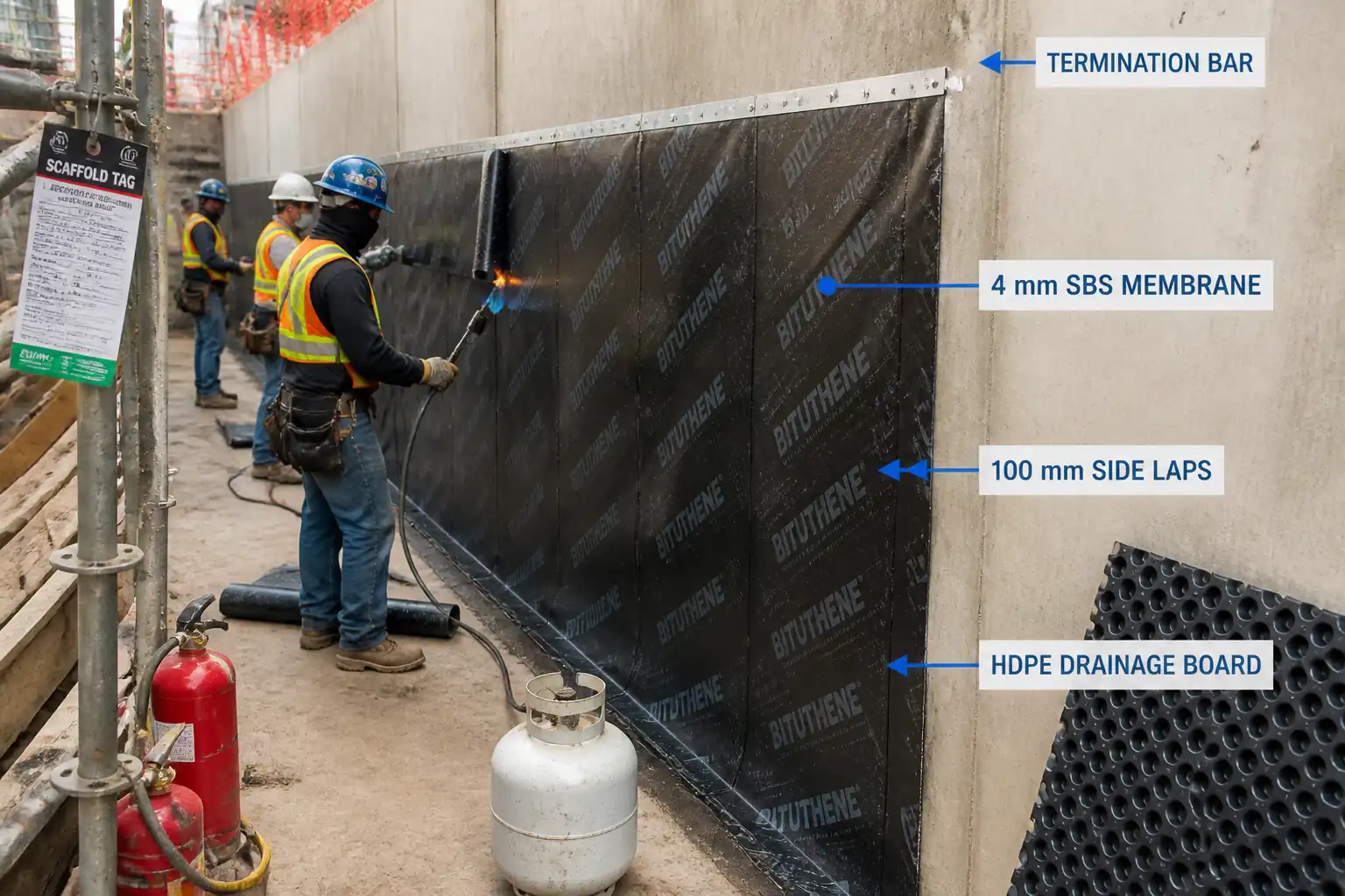
- Install a manufacturer-approved, pre-applied HDPE composite blindside waterproofing membrane system to below-grade walls and slab edges formed against shotcrete or shoring/lagging systems.
- Works include substrate readiness, sheet layout, mechanical fixing to the support system, self-adhesive lap sealing, internal/external corner treatment, service penetration details, top terminations, local repairs, protection during rebar placement, and pre-pour inspections.
Locations
- Deep basement perimeter walls formed against: soldier piles and timber/steel lagging, secant piles, diaphragm walls, or shotcrete SOE faces.
Exclusions/Interfaces
- Ground improvement/SOE works by others.
- Concrete placement by General Contractor; coordination and protection requirements included herein.
- Drainage composite/collection systems by others unless noted.
Performance Intent
- Provide a continuous waterproofing barrier delivering the design water-resistance grade per BS 8102 (e.g., Grade 2 or Grade 3 for habitable basements) [Verify per project specifications].
- Membrane-to-concrete adhesion intended to preclude lateral water migration in the event of localized damage (pre-applied adhesive bond system).
References
| Document Type | Reference / Number | Revision | Notes |
|---|---|---|---|
| Standard | BS 8102:2022 | ||
| Standard | BS EN 13967 | Product conformity [Verify per project specifications] | |
| Standards | ASTM D903/D882/D6392 | Field applicability for lap peel verification as agreed with manufacturer/Engineer | |
| Standard | ASTM D5385 | ||
| Standard | ASTM C920 | ||
| Standards | ACI 301/117/350 | For interface and vibration practices adjacent to membrane | |
| Standards | ISO 9001/14001/45001 | ||
| Manufacturer | Latest issue | Follow manufacturer project-specific instructions where more stringent than this method |
Responsibilities
| Role | Responsibility | Name / Party |
|---|---|---|
| Project Manager | Project Manager | Main Contractor |
| Construction Manager | Construction Manager | Main Contractor |
| QA/QC Engineer | QA/QC Engineer | Main Contractor |
| HSE Officer | HSE Officer | Main Contractor |
| Site Engineer | Site Engineer/Surveyor | Main Contractor |
| Foreman | Waterproofing Foreman & Crew | Approved Subcontractor |
| Engineer | Engineer/Consultant | Engineer/Consultant |
Resources
| Resource Type | Description | Quantity | Remarks |
|---|---|---|---|
| Manpower | Approved waterproofing installers | 6–10 | |
| Manpower | Foreman + QA/QC Engineer + HSE Officer | 3 | |
| Manpower | Site Engineer/Surveyor support | 1–2 |
Materials
| Material | Specification / Grade | Quantity | Remarks |
|---|---|---|---|
| HDPE blindside membrane | Hydrostatic resistance >70 m (ASTM D5385) [Verify]; Lap compatibility per system | Delivered in sealed rolls; store upright, dry | |
| Detailing membrane | Same system manufacturer | ||
| Lap tapes | Manufacturer-approved | ||
| Primer/activator | VOC limits [Verify per project] | ||
| Termination system | Sealant ASTM C920 Class [Verify]; SS A2/A4 fasteners | ||
| Accessories | Hydrophilic waterstop swell 150–300% [Verify]; Non-shrink grout ASTM C1107 | ||
| Protection | Non-woven PP geotextile | Geotextile 300 g/m² typical [Verify] |
Equipment
| Equipment | Capacity / Type | Quantity | Inspection Required |
|---|---|---|---|
| Drill/driver | 2–3 | ||
| As required | |||
| Rollers | 2 | ||
| MEWP/Scaffold | As needed | ||
| Set | |||
| Set |
Prerequisites
Approvals & Documents
- Approved shop drawings and method statement, ITP, and manufacturer installation manual.
- Material submittals approved; COC/COA and batch numbers available.
Permits & Coordination
- Permit to work in deep excavation/at height; PAT/hot works permits if applicable [Verify per project HSE plan and local regulations].
- Coordination meeting with SOE contractor, rebar/concrete teams, and waterproofing applicator.
Site Readiness
- SOE/shotcrete face completed, surveyed, and handed over; remove loose material, protruding rebars, tie-backs trimmed flush; fill voids >20 mm with non-shrink grout; knock off fins to ≤5 mm; no standing water >3 mm.
- Backing/leveling boards installed where gaps between lagging exceed 20 mm; joints staggered; fasten securely.
- Datum lines established for sheet layout and top termination.
Environmental Conditions
- Ambient/application temperature within manufacturer limits (typ. -5°C to +50°C) [Verify per product]; avoid installation during precipitation or on wet/icy surfaces unless system allows.
Training & Tools
- Installers trained/approved by manufacturer; toolbox talk completed; calibrated tools available; rollers and tapes on hand.
Hold Points
- Pre-start inspection and mock-up approval prior to full production.
- Pre-pour hold point after completion of membrane and detailing, before reinforcement congestion prevents access.
Method Sequence
| Step | Activity | Description | Responsibility | Inspection / Hold Point |
|---|---|---|---|---|
| 1 | Pre-start meeting & mock-up | Review drawings, risk controls, and perform minimum 2 m x 2 m mock-up including one internal corner, one penetration, and a sealed lap for peel check. | PM/QAQC/Foreman/Manufacturer Rep | Witness by Engineer (Hold Point) |
| 2 | Substrate preparation | Clean, brush/vacuum SOE/shotcrete face. Cut back protrusions to ≤5 mm. Fill voids >20 mm; form 25 mm cementitious fillets at internal corners and around tie-backs as needed. | Foreman | Visual |
| 3 | Install backing/leveling boards (if required) | Fix 12–18 mm plywood/board over lagging gaps >20 mm; ensure firm support for membrane. Seal protruding fasteners heads flush. | Carpentry crew | Visual |
| 4 | Set out sheet layout | Chalk datum lines. Plan shingle-style installation from highest point downward so laps shed water. Minimize cut pieces; maintain lap directions. | Site Engineer/Foreman | Visual |
| 5 | Starter strip at slab/wall junction | Apply detailing strip 300 mm wide along slab interface or kicker line. Where kicker present, wrap onto slab/blinding by 150 mm. | Applicators | Visual |
| 6 | Fix first course of sheets | Present first sheet plumb. Mechanically fasten along top edge only using corrosion-resistant anchors with 25–35 mm sealing washers at 300 mm c/c (max) and ≥50 mm from edge. Additional intermediate fixings only where required by system; seal penetrations. | Applicators | Visual |
| 7 | Side laps (longitudinal) | Provide minimum 100 mm overlap. Clean lap zones; apply double-sided tape/activator as specified; close lap and consolidate with 15–20 kg roller with 3 passes. | Applicators | Visual + feel |
| 8 | End laps (transverse) | Stagger end laps; minimum 150 mm overlap. Treat as per side laps. Avoid T-joints where possible; if unavoidable, apply 200 mm x 200 mm cover patch. | Applicators | Visual |
| 9 | Corners and edges | Internal corners: install 300 mm detailing strip centered on corner over 25 mm fillet; then main sheet. External corners: preformed corner or 300 mm corner strip first, then sheet; ensure 150 mm min cover beyond arris. | Applicators | Visual |
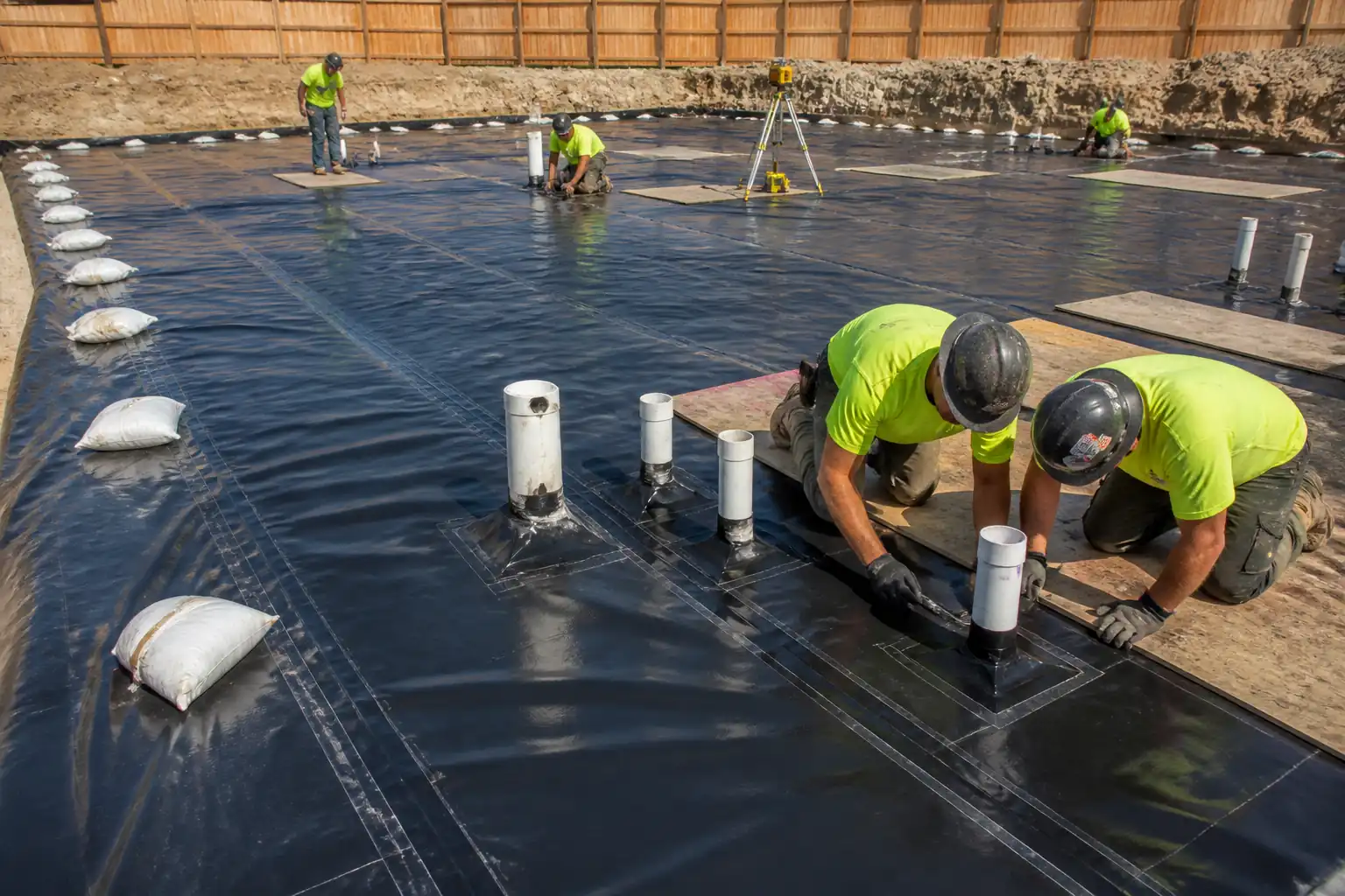
| 10 | Penetrations (pipes, anchors) | Fit preformed boot or wrap detailing strip; lap to main membrane ≥150 mm all around. Install hydrophilic waterstop around pipe, 25–50 mm from membrane bond line [Verify]. Fill annulus with ASTM C1107 grout. For puddle flanges, integrate per manufacturer drawing. | Applicators | Visual |
| 11 | Intermediate sealing and repairs | Seal fastener penetrations; repair damage with detailing patches extending ≥150 mm beyond defect. Remove and replace fishmouths; do not slit without patch. | Applicators | Visual |
| 12 | Top termination | Continue membrane to designed termination elevation. Fix termination bar at ≤200 mm c/c with SS anchors; apply continuous 10 x 10 mm compatible sealant bead along top edge. Tie into above-grade waterproofing as detailed. | Applicators | Visual/torque spot-check |
| 13 | Protection prior to rebar placement | Lay temporary walkway boards; install geotextile protection where specified. Instruct rebar crew: use plastic chairs with min 100 x 100 mm base pads; no dragging steel; no welding/hot works within 1 m without protection. | Foreman/HSE | Daily |
| 14 | Pre-pour inspection (Hold Point) | Joint-by-joint inspection; verify laps, corners, penetrations, terminations, repairs, cleanliness. Remove debris. Sign ITP. | QA/QC + Engineer | Hold Point |
| 15 | Concrete placement interface | Coordinate pour sequence to avoid rebound/impact on membrane. Internal vibration per ACI 301; keep vibrator ≥50 mm from membrane. Prevent form-release agents contacting membrane. | GC Concrete Team | Supervision |
| 16 | Post-pour checks | Inspect accessible terminations/penetrations; re-seal any disturbed sealant; document as-built. Monitor for leaks during dewatering or initial wetting. | QA/QC | Visual |
Safety Controls
Task-specific hazards and controls
- Hazard: Deep excavation and uneven working platforms.
- Consequence: Falls, entrapment, struck-by incidents.
- Engineering/procedural control: Certified access/egress, edge protection where feasible, leveled working platforms with load capacity verified; exclusion zones demarcated; daily geotechnical/SOE condition checks.
- Required PPE: Hard hat, hi-vis, safety boots, gloves.
- Collective measures: Edge barriers, walkways, lighting to 200 lux min in work area [Verify].
-
Inspection/permit: Daily excavation inspection; PTW for work in excavation [Verify per project HSE plan and local regulations].
-
Hazard: Work at height for upper membrane courses/terminations.
- Consequence: Fall from height.
- Control: Use MEWP or compliant scaffold; full-body harness with short lanyard; maintain 3 points of contact; no standing on lagging.
- PPE: Harness with double lanyard, helmet with chin strap.
- Collective: Guardrails on scaffold; toe boards.
-
Inspection/permit: Work-at-height permit; MEWP pre-use inspection; operator certification.
-
Hazard: Mechanical fixing (drilling/PAT tools).
- Consequence: Hand injuries, flying debris, hearing loss.
- Control: Use guarded tools, dust extraction, correct bits/anchors; PAT use only with permit and backstops; maintain minimum standoff from utilities.
- PPE: Safety glasses/face shield, cut-resistant gloves, hearing protection.
- Collective: Exclusion zone; debris screens when overhead.
-
Inspection/permit: Tool inspection; PAT permit; verify substrate reinforcement/embedded hazards by scan where required.
-
Hazard: Chemical exposure from primers/adhesives/sealants.
- Consequence: Dermal/respiratory irritation, fire risk (solvent-based).
- Control: Prefer low-VOC, non-flammable products; apply in ventilated areas; decant in trays; no ignition sources; follow SDS.
- PPE: Nitrile gloves, safety glasses, half-mask respirator with organic vapor filters where required.
- Collective: Forced ventilation if in confined zones.
-
Inspection/permit: COSHH assessment/SDS; hot work permit if heat used; gas testing if confined.
-
Hazard: Membrane damage during rebar placement/handling.
- Consequence: Leaks due to punctures/tears.
- Control: Temporary walkway boards; instruct rebar crew; plastic chairs with base pads; no dragging steel.
- PPE: Gloves, safety boots.
- Collective: Toolbox talk; spotters during rebar installation.
-
Inspection/permit: Daily integrity checks; pre-pour inspection hold point.
-
Hazard: Lifting and manual handling of rolls (30–50 kg typical).
- Consequence: Musculoskeletal injuries.
- Control: Team lifts or mechanical aids; limit lift height; use roll dollies.
- PPE: Back support as needed, gloves.
- Collective: Manual handling training.
-
Inspection/permit: Supervisor monitoring.
-
Hazard: Noise and dust from drilling/shotcrete residues.
- Consequence: Hearing loss, respiratory irritation.
- Control: Wet/dust extraction drilling where possible; maintain noise <85 dBA 8-hr TWA [Verify]; rotate tasks.
- PPE: Hearing protection, dust masks/respirators as required.
- Collective: Barriers and signage.
-
Inspection/permit: Noise/dust spot measurements as required.
-
Hazard: Confined space-like conditions in deep shafts.
- Consequence: Asphyxiation, poor egress.
- Control: Ventilation plan; continuous gas monitoring if applicable; standby attendant.
- PPE: Respirator if required; communication devices.
- Collective: Rescue plan ready.
- Inspection/permit: Confined space permit where applicable.
Environmental Controls
Controls
- Material storage and waste
- Store rolls upright on pallets under cover; prevent contamination/runoff. Segregate HDPE off-cuts and tapes; recycle where possible. Dispose in accordance with local regulations.
- VOC/solvents
- Select low-VOC primers/sealants where feasible. Use in well-ventilated areas; keep lids closed; spill kits available. Maintain SDS on site.
- Noise and dust
- Use low-noise tools and dust extraction. Limit drilling to permitted hours. Dampen surfaces to suppress dust if not affecting membrane.
- Water management
- Prevent washout water/adhesive residues from entering drains. Provide drip trays for liquid products. Maintain silt control near sumps.
- Energy and lighting
- Use LED task lighting; shut off idling equipment.
- Incident response
- Spill response plan with absorbents; report and record environmental incidents per EMS [Verify per project requirements].
QA/QC
Submittals and Records
- Product datasheets, SDS, COC/COA, installer approval letter, shop drawings, method statement, ITP, and mock-up records.
- Daily installation logs, lap peel test logs, inspection requests (IRs), checklists, as-built drawings, NCRs/CARs.
Material Control
- Verify batch numbers, shelf life, storage conditions. Reject damaged rolls or expired chemicals.
Workmanship Tolerances
- Side lap width: ≥100 mm; End lap width: ≥150 mm [Verify per manufacturer/project].
- Fastener spacing top edge: ≤300 mm c/c; termination bar: ≤200 mm c/c.
- Corner fillet: 25 mm x 25 mm (cementitious) unless otherwise specified.
- Patches extend ≥150 mm beyond defect in all directions.
Testing and Inspection Frequency
- Visual inspection: 100% of area, every shift.
- Field lap peel verification: 1 test per 20 m of lap or min 2 per day; acceptance ≥ manufacturer’s minimum (typ. ≥1.0 N/mm) [Verify].
- Adhesion/activation in cold weather: additional checks each time temperature <10°C [Verify thresholds per product].
- Documented Engineer/Third-party hold point prior to pouring.
Acceptance Criteria
- Membrane continuous without puncture, wrinkle, fishmouth, or contamination; laps sealed and consolidated; all penetrations/corners detailed; terminations fixed and sealed; protection measures in place; ITP signed off.
Nonconformance & Repairs
- Mark and cordon suspect areas. Execute repair with cleaning, priming (if required), and patching using compatible detailing strips with minimum 150 mm overlap. Re-test peel as applicable. Record in repair log and as-built.
Manufacturer Support
- Arrange periodic site attendance by manufacturer’s technical representative; secure written confirmation of compliance where required by contract.
Attachments
Attachments / Appendices
- Manufacturer’s system installation manual and standard details.
- Shop drawings: sheet layout plan, lap directions, corner and penetration details, termination details.
- Mock-up approval record and photos.
- Daily inspection checklist template and lap peel test log template.
- SDS for all chemical products (primers, sealants, adhesives).
- Training/approval certificates for applicators.
- As-built markups showing any deviations and repair locations.
This content is a read-only public reference. Download or customize to get an editable version.
ITP preview
The first inspection activities from the linked ITP for Method Statement: Pre-applied HDPE Blindside Waterproofing for Deep Basements (Shotcrete/Shoring):
| Activity | Inspection / Test | Acceptance Criteria | Responsibility | Record |
|---|---|---|---|---|
| Pre-start documentation and materials | Verify approvals, SDS, COC/COA, storage conditions | Submittals approved; materials per EN 13967; batches recorded | QA/QC Engineer / Engineer (Witness) | IR, Material inspection report |
| Substrate readiness (SOE/shotcrete) | Surface cleanliness, voids/protrusions, moisture, fillets | No standing water >3 mm; voids >20 mm filled; protrusions ≤5 mm; fillets 25 mm | QA/QC Engineer / Engineer (Witness) | Checklist, Photos |
| Mock-up verification | Peel check of sample lap per ASTM D903 practice | Meets/Exceeds manufacturer minimum peel [Verify] | QA/QC / Engineer (Witness) / Manufacturer Rep | Mock-up IR |
Showing 3 of 10 inspection activities. View full ITP →
Related Inspection and Test Plan
An Inspection and Test Plan (ITP) is available for Method Statement: Pre-applied HDPE Blindside Waterproofing for Deep Basements (Shotcrete/Shoring). The ITP defines the inspection activities, acceptance criteria, hold and witness points, responsible parties, and records required to verify the work described in this method statement.
View the Method Statement: Pre-applied HDPE Blindside Waterproofing for Deep Basements (Shotcrete/Shoring) ITP →Frequently asked questions
Continue with related Quollnet resources connected to this method statement.