
Method Statement: Installation of Underground uPVC/HDPE Gravity Drainage Networks – Method Statement
AI-assisted method statement with matching ITP, PDF download, and Excel export.
More than a static template
Unlike a downloadable Word or PDF template, this method statement is an AI-assisted editable starting point connected directly to a matching Inspection and Test Plan. Every section is structured, project-adaptable, and ready to export.
- AI-assisted drafting — Customize every section with AI for your specific project scope.
- Linked ITP — A matching inspection and test plan is generated alongside the method statement.
- Multiple export formats — Download as a formatted PDF or editable Excel spreadsheet.
- Editable starting point, not a final document — Review, verify, and adjust all content against your project requirements before use.
Static template vs. Quollnet workflow
| Feature | Static template | Quollnet |
|---|---|---|
| Project-specific content | Manual fill-in required | AI-assisted customization |
| Linked ITP | Separate document, no link | Matching ITP included |
| Export formats | Usually PDF only | PDF and Excel |
| Structured sections | Free-form layout | 13 standardized sections |
| Saved to your account | Local file only | Cloud-saved, reusable |
| Content accuracy | You verify everything | AI-assisted, you still verify |
| Cost | Often free but time-intensive | Free to customize and download |
What you can customize
When you save this method statement to your account, every section becomes editable. The following 13 sections are included:
- Scope — Defines the activity and its boundaries.
- References — Standards, specifications, and drawings.
- Responsibilities — Roles and accountabilities.
- Resources — Labour, plant, and equipment summary.
- Materials — Materials and compliance requirements.
- Equipment — Tools and equipment details.
- Prerequisites — Hold points and pre-conditions.
- Method sequence — Step-by-step construction sequence.
- Safety controls — HSE risk controls and PPE.
- Environmental controls — Environmental mitigation measures.
- QA/QC — Quality inspection and test requirements.
- ITP — Inspection and Test Plan table (has its own page).
- Attachments — Referenced drawings and documentation.
Why this method statement is used
This method statement is used to define and communicate the approved procedure for carrying out method statement: installation of underground upvc/hdpe gravity drainage networks on site. It ensures the work is planned in advance, the correct resources and controls are in place, and all personnel understand responsibilities, sequence, quality requirements, and safety controls before work begins. It aligns site execution with the documented scope and acceptance expectations.
Who uses this method statement
This method statement is used by contractors, site supervisors, project engineers, QA/QC engineers, HSE officers, consultants, and client representatives. It serves as a shared reference for planning, execution, supervision, inspection, and approval of the activity on site.
When it is prepared and submitted
The method statement is prepared before the work activity starts and submitted as part of the pre-construction documentation package for review and approval.
Who reviews or approves it
The method statement is usually submitted to the client representative, consultant, resident engineer, or project management consultant for review and approval before the work commences.
Important approval note
This method statement is an AI-assisted editable starting point, not a pre-approved document. Before use on any project, all content must be reviewed and approved by the relevant parties (superintendent, principal contractor, or client representative) in accordance with your contract and project quality plan.
For example: if your specification requires a departure from a referenced standard, that departure must be documented and approved separately — this method statement will not capture that automatically. Always verify against your applicable drawings, specifications, and regulatory requirements.
Method statement content
Scope
Purpose
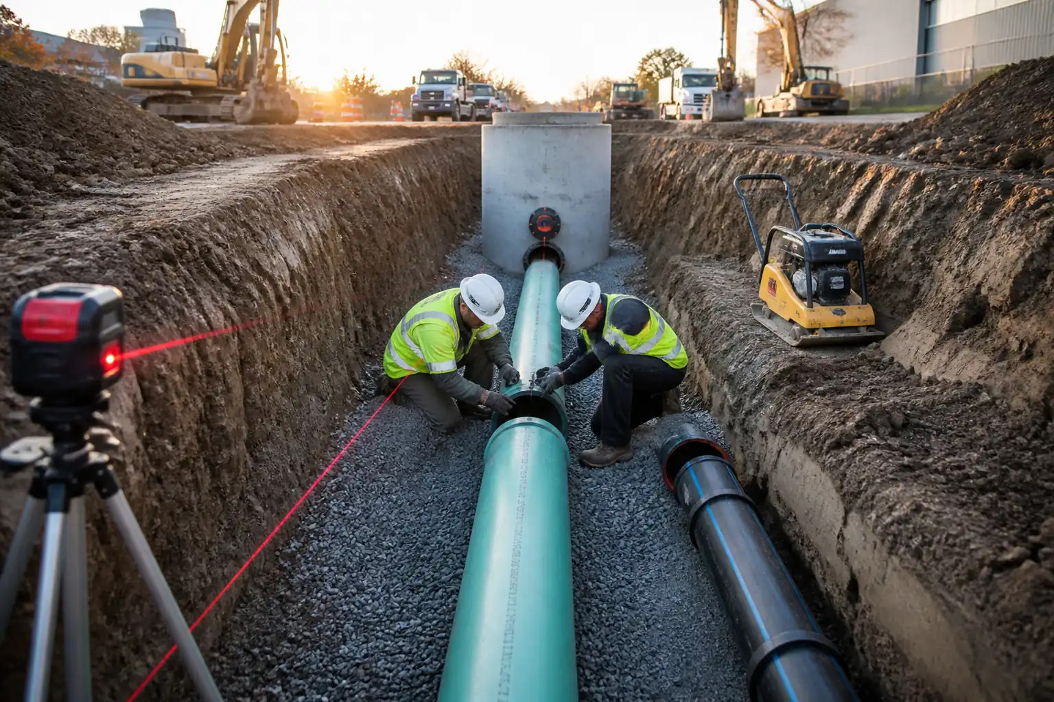
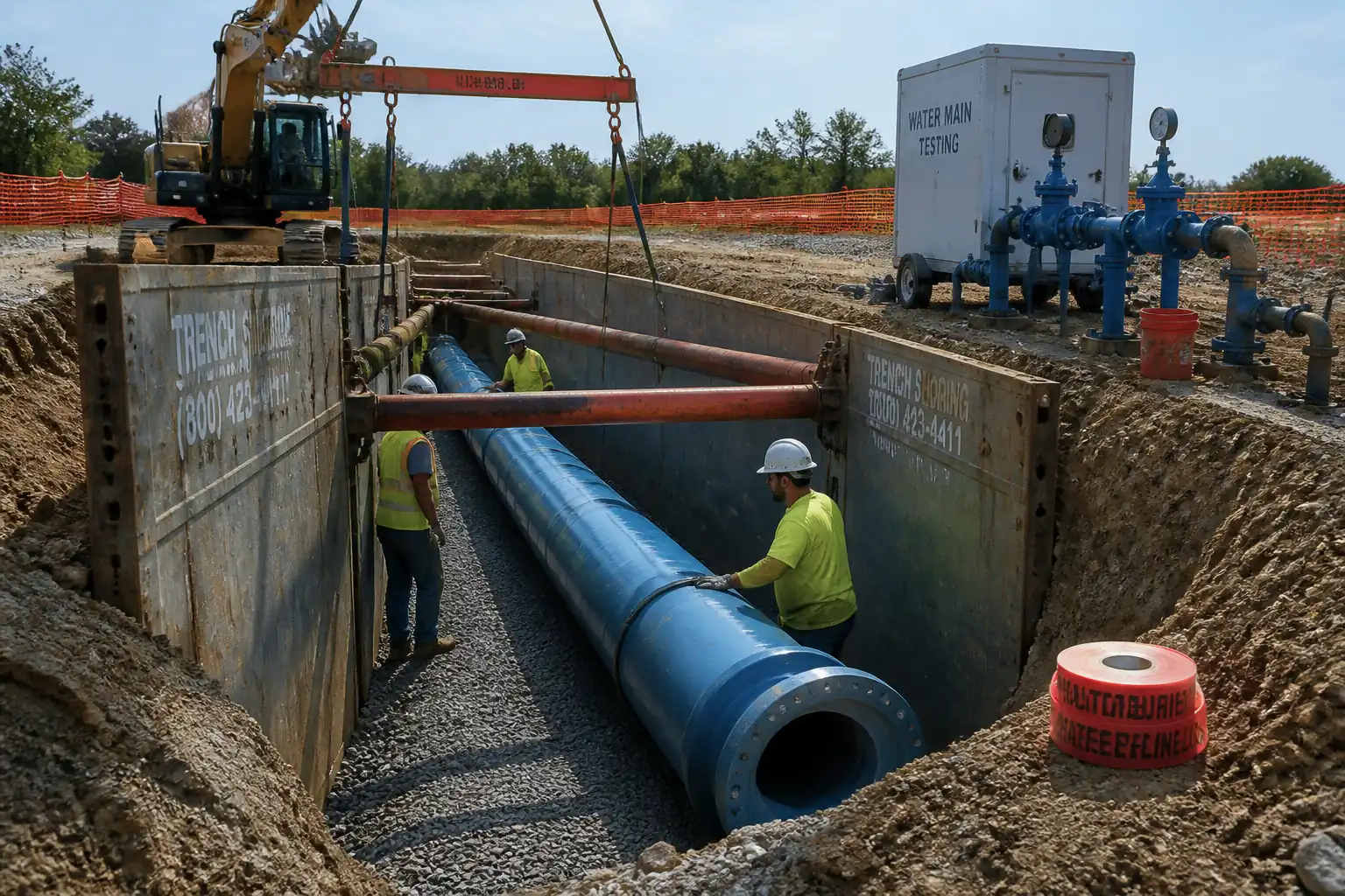
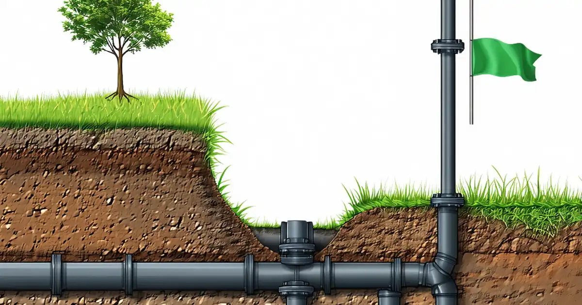
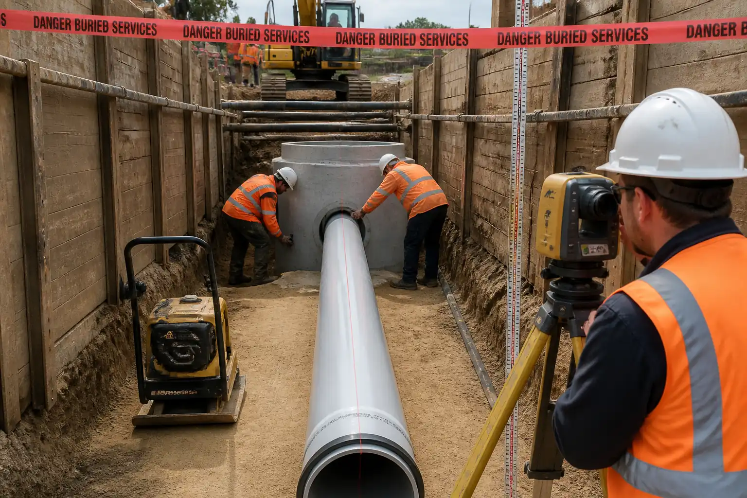
This method statement details the complete procedure for installation of underground uPVC/HDPE gravity drainage pipelines, including survey and setting out, trench excavation and support, dewatering, bedding preparation, pipe laying and jointing (push-fit/solvent-weld for uPVC; butt/electrofusion for HDPE), connections to manholes and chambers, backfilling in layers, compaction and field density testing, leakage and deflection testing, CCTV survey, and reinstatement up to formation level.
Extent of Works
- Pipe diameters: DN100–DN600 [Verify per project specifications]
- Locations: off-carriageway and within carriageway/travelled ways
- Depth of cover: typically ≥600 mm verge/landscaped areas; ≥900 mm under roads [Verify per project specifications]
- Interfaces: tie-in to existing manholes, new precast manholes, catchpits, gullies, laterals, cleanouts/rodding eyes, and outfalls
Exclusions
- Pressurised pipelines and rising mains
- Structural design of temporary works/shoring (provided separately)
- Permanent pavement reinstatement (covered by separate method, unless otherwise stated)
References
| Document Type | Reference / Number | Revision | Notes |
|---|---|---|---|
| Standard | ASTM D2321 | ||
| Standard | BS EN 1401-1 | ||
| Standard | BS EN 12666-1 | ||
| Standard | ISO 21307 / ASTM F2620 | ||
| Standard | ISO 12176 | ||
| Standard | EN 1610 | ||
| Standard | BS EN 1917 / ASTM C478 | ||
| Standard | ASTM C923 | ||
| Standard | ASTM D698 / ASTM D1557 | ||
| Standard | ASTM D6938 | ||
| Standard | BS 6031 / EN 1997-1 | Temporary works design to BS 5975 where applicable [Verify per project]. | |
| Guideline | WRC MSCC (latest) / NASSCO PACP | ||
| Standard | ASCE 38 / PAS 128 | For pre-excavation utility surveys [Verify per project]. |
Responsibilities
| Role | Responsibility | Name / Party |
|---|---|---|
| PM | Authorize MS/ITP, ensure competent personnel and permits | Contractor |
| SE | Check survey controls, verify line/level, request inspections | Contractor |
| QA/QC | Raise ITP hold/witness, review test results, NCR management | Contractor |
| HSE | Issue permits (PTW), enforce controls, toolbox talks | Contractor |
| Surveyor | Establish/control benchmarks, check invert levels and slopes | Contractor |
| Foreman | Ensure workmanship, plant coordination, safe systems of work | Contractor |
| Technician | Follow ISO 21307/ASTM F2620, maintain weld logs, equipment calibration | Contractor |
| Crew | Comply with tolerances, protect pipes, housekeeping | Contractor |
| 3rd Party | Provide calibrated equipment and certified results | Independent Lab |
| Engineer | Witness/hold points per ITP, approve records | Engineer |
Resources
| Resource Type | Description | Quantity | Remarks |
|---|---|---|---|
| Personnel | 1 Foreman, 1 Site Engineer, 1 Surveyor, 1 HSE Officer, 1 Fusion Technician (if HDPE), 6–10 Pipe Layers/Laborers, 1 Excavator Operator, 1 Banksman | ~12–16 | |
| Subcontractor | CCTV survey and leak/air testing | As required |
Materials
| Material | Specification / Grade | Quantity | Remarks |
|---|---|---|---|
| PVC-U | DN100–DN600, SDR per design | ||
| HDPE (PE100) | DN100–DN600 | ||
| EPDM/NBR | |||
| Solvent cement/primer | |||
| Lubricant | |||
| Granular material | Class I/II per ASTM D2321 | ||
| Fill | |||
| EPDM/SS clamp | |||
| Tape/Wire |
Equipment
| Equipment | Capacity / Type | Quantity | Inspection Required |
|---|---|---|---|
| 20–35 t | 1–2 | Yes | |
| As required | Yes | ||
| 3–6" pumps | 1–2 | ||
| 1 set | |||
| 3–4 | |||
| 1 | Yes | ||
| 1 | |||
| 1 | |||
| 1 |
Prerequisites
- Approved IFC drawings, specifications, and this Method Statement with ITP.
- Permit to Dig with utility survey (ASCE 38/PAS 128 quality level), mark-out, and positive identification via vacuum potholing where conflicts are suspected.
- Temporary Works Design for trench support approved where trench depth/ground conditions require shoring [Verify per project].
- Traffic Management Plan approved where working in carriageways.
- Dewatering/Discharge permit in place if groundwater is anticipated.
- Materials approvals (Pipes, gaskets, cement/primer, connectors) and delivery inspections completed.
- Calibration certificates current for lasers, fusion equipment, density gauge.
- Competency/qualifications: fusion technician certified; nuclear gauge operator certified; plant operators licensed; confined space team trained.
- HSE documentation: Task risk assessment (RAMS), toolbox talk completed, emergency/ rescue plan for confined spaces, Hot Work Permit (for fusion) as needed.
- Weather and groundwater conditions assessed; works sequenced to minimize open trench length.
- Pre-start coordination with adjacent trades/utilities; notification to stakeholders as required.
Method Sequence
| Step | Activity | Description | Responsibility | Inspection / Hold Point |
|---|---|---|---|---|
| 1 | Site handover and survey control | Confirm benchmarks and establish control points along alignment. Protect and verify before use. | Surveyor / Site Engineer | Internal check |
| 2 | Utility detection and permits | Scan with cable/pipe locator and GPR; mark utilities. Obtain Permit to Dig. Pothole to confirm depth/position where required. | HSE / Site Engineer | Hold Point: Permit to Dig |
| 3 | Setting out line and level | Set out pipe centerline and manhole positions. Establish design invert at start and end, and intermediate points using pipe laser. | Surveyor | Witness by QA/QC |
| 4 | Trench excavation | Excavate to formation level considering bedding thickness. Maintain safe side slopes or install shoring/boxes. Limit open trench length to manageable sections (e.g., ≤30–50 m) [Verify]. | Foreman / Excavator Operator | Hold Point: Formation level check |
| 5 | Dewatering and trench stability | Install sump pumps/wellpoints if required. Maintain water level below formation. Prevent soil piping and base instability. | Foreman | Routine |
| 6 | Formation preparation | Trim formation; remove soft spots. If over-excavated, fill with compacted bedding material. | Foreman | Witness |
| 7 | Bedding placement | Place 100–150 mm bedding (Class I/II). Screed to designed grade using laser. Do not compact directly under pipe seat excessively. | Foreman / Site Engineer | Hold Point: pre-lay bedding |
| 8 | Pipe laying orientation | Lay from downstream to upstream; sockets facing upstream. Verify pipe cleanliness before jointing. | Pipe Layer | Continuous |
| 9 | uPVC push-fit jointing | Apply approved lubricant to spigot and gasket. Insert to witness mark with controlled force. Ensure gasket not displaced. | Pipe Layer | Witness |
| 10 | uPVC solvent-weld jointing (if specified) | Dry-fit to confirm interference. Clean/prime (ASTM F656). Apply cement (ASTM D2564) evenly, assemble with 1/4 turn. Wipe excess; support until set. | Pipe Layer | Witness / Hot Work permit not required (cold bond) |
| 11 | HDPE butt fusion | Face/align pipes; heat to specified bead; apply fusion pressure/time; cool under pressure. Record parameters using data logger. | Fusion Technician | Hold/Witness |
| 12 | HDPE electrofusion (if used) | Scrape oxide layer, clean, insert alignment clamps, connect EF box, weld per barcode parameters, allow full cooling. | Fusion Technician | Witness |
| 13 | Alignment and gradient verification | Use pipe laser/level to confirm invert at each pipe and at manholes. | Site Engineer | Witness |
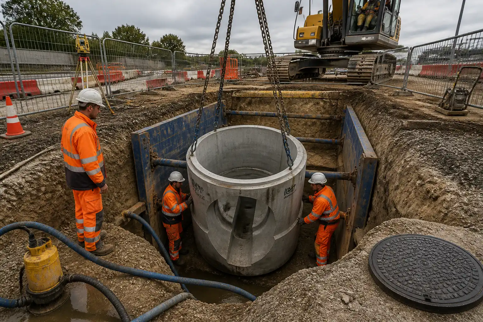
| 14 | Manhole connection (new or existing) | Core drill manhole wall to pipe OD; fit flexible connector (ASTM C923). Install rocker pipes (0.5–1.0 m) adjacent to manhole. Rebench as required; seal watertight. | Foreman / Mason | Hold Point: before backfill at connection |
| 15 | Initial surround and sidefill | Place and compact sidefill evenly to springline and to 150–300 mm above crown. Hand-tamp near pipe, avoid displacement. | Foreman | Witness |
| 16 | Warning tape and tracer wire | Install detectable warning tape ~300 mm above pipe. Lay tracer wire along trench with test boxes at access points [if required by Client]. | Foreman | Witness |
| 17 | Backfill in layers (non-traffic) | Place selected backfill in ≤200–250 mm layers and compact. | Foreman | Witness |
| 18 | Backfill in carriageway | Place engineered backfill per authority spec in ≤150–200 mm layers; compact with suitable equipment; protect pipe from dynamic loads until ≥300 mm cover. | Foreman | Hold/Witness |
| 19 | Leakage testing (gravity) | After initial backfill and stabilization, test per EN 1610 using air or water as specified. Isolate sections between manholes. | QA/QC / Specialist | Witness (Engineer) |
| 20 | Deflection testing (flexible pipes) | Mandrel/deflectometer test after suitable period (e.g., 30 days) or as directed. | QA/QC / Specialist | Witness (Engineer) |
| 21 | CCTV survey | CCTV inspect entire run, record observations and coding per WRC MSCC or NASSCO PACP. | Specialist | Witness (Engineer) |
| 22 | As-built survey | Survey inverts, coordinates of manholes/laterals, and pipe gradients. Update GIS if applicable. | Surveyor | Review |
| 23 | Surface reinstatement to formation | Reinstate to formation/subgrade or as specified, protect awaiting final pavement. | Foreman | Witness |
| 24 | Demobilization and housekeeping | Remove shoring, signage, surplus materials. Close permits. Handover O&M/records. | PM / QA/QC | Final inspection |
Health, Safety and Environment (HSE) - Safety Controls
Risk-assessed, task-specific controls
- Hazard: Underground utility strike (electric/gas/fiber)
- Likely consequence: Electrocution, gas explosion, service outage
- Engineering/procedural control: Permit to Dig; pre-excavation GPR/CAT scan; mark and maintain exclusion zones; vacuum potholing to verify; hand-dig within 1 m of suspected utilities
- Required PPE: Dielectric gloves when required, safety boots, arc-rated PPE if working near HV per utility rules [Verify]
- Collective preventive measure: Physical barriers/goalposts over known utilities; spotter/banksman during excavation
-
Inspection/permit/supervision: Permit to Dig; daily briefings; utility owner approvals where needed
-
Hazard: Trench collapse/engulfment
- Likely consequence: Fatal crush/asphyxiation
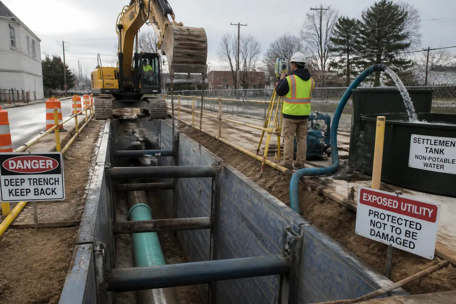
- Engineering/procedural control: Shoring/trench boxes per Temporary Works Design; keep surcharge loads ≥1 m from edge; staged excavation; limit open length; do not enter unsupported trench >1.2 m deep
- Required PPE: Hard hat, boots, gloves, hi-vis, gas monitor if required
- Collective preventive measure: Edge protection (guardrails), ladder access every 6–9 m, trench crossing boards
-
Inspection/permit/supervision: Daily competent person inspection; after rain or dewatering changes; excavation permit
-
Hazard: Plant–people interface (struck-by/crushed)
- Likely consequence: Serious injury/fatality
- Engineering/procedural control: Segregated walkways; exclusion zones; assigned banksman; 360° cameras/alarms; reverse alarms
- Required PPE: Hi-vis, hard hat, steel-toe boots
- Collective preventive measure: Physical barriers and spotters; traffic management per approved plan
-
Inspection/permit/supervision: Daily plant checks; TM audits
-
Hazard: Lifting of pipes/manhole components
- Likely consequence: Dropped load injuries, crush damage to pipes
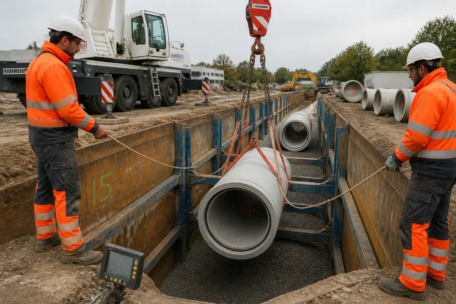
- Engineering/procedural control: Certified lifting accessories; tag lines; lift plan; avoid lifting over persons; use spreader bars for long pipes
- Required PPE: Helmet with chin strap, gloves, boots, eye protection
- Collective preventive measure: Exclusion zone around lift; competent crane/rig operator
-
Inspection/permit/supervision: LOLER/third-party certificates; lifting plan approval; appointed person supervision
-
Hazard: Confined space entry to manholes
- Likely consequence: Asphyxiation/toxic exposure (H2S), drowning
- Engineering/procedural control: Confined Space Permit; gas test (O2, H2S, CO, LEL); forced ventilation; top-man standby; retrieval tripod/winch; rescue plan and drills
- Required PPE: Harness, gas detector, gloves, boots, helmet, eye protection
- Collective preventive measure: Barricade openings; continuous atmospheric monitoring
-
Inspection/permit/supervision: Permit to Enter; competent entry supervisor
-
Hazard: Hot surfaces/electrical during PE fusion
- Likely consequence: Burns/electric shock
- Engineering/procedural control: Dedicated fusion area; barriers; verify voltage; residual current device (RCD); cool-down times enforced
- Required PPE: Heat-resistant gloves, long sleeves, face shield/eye protection
- Collective preventive measure: Fire extinguisher CO2/foam available; no flammables nearby
-
Inspection/permit/supervision: Equipment PAT/calibration; hot work permit if local rules require [Verify]
-
Hazard: Solvent cement/primer vapors (uPVC)
- Likely consequence: Eye/respiratory irritation, dermatitis, fire risk
- Engineering/procedural control: Use in well-ventilated areas; lids closed when not in use; small decanting; no ignition sources
- Required PPE: Nitrile gloves, safety glasses, half-mask respirator with organic vapor cartridges if ventilation poor [Verify]
- Collective preventive measure: Spill kit; SDS available; storage in flammable cabinet
-
Inspection/permit/supervision: COSHH/chemical handling review; container expiry check
-
Hazard: Water ingress/flooding in trench
- Likely consequence: Drowning, floatation of pipes, base instability
- Engineering/procedural control: Predict groundwater; install pumps/standby unit; place sandbags/berms to divert stormwater; secure pipes from flotation during events
- Required PPE: Waders as needed, gloves, boots
- Collective preventive measure: Emergency pump; alarm for heavy rain
-
Inspection/permit/supervision: Dewatering permit; monitor discharge quality
-
Hazard: Noise/vibration from compaction equipment
- Likely consequence: Hearing loss, HAVS
- Engineering/procedural control: Select low-vibration tools; job rotation; maintain equipment
- Required PPE: Hearing protection (SNR per site), anti-vibration gloves
- Collective preventive measure: Noise barriers where feasible
- Inspection/permit/supervision: Exposure monitoring; HAVS logs
[Verify per project HSE plan and local regulations]
Environmental Controls
- Spoil management: Segregate reusable material from waste; stockpile on impermeable mat away from drains; cover to prevent runoff/dust.
- Silt and water control: Use silt fences and inlet protection; route dewatering to settlement tank/bag; discharge only under permit with turbidity within limits [Verify].
- Fuel/chemical management: Bunded areas for fuels; drip trays under pumps; spill kits within 20 m; immediate cleanup and report.
- Dust suppression: Water bowsers/misting during dry conditions; wheel wash when exiting public roads.
- Noise/time restrictions: Adhere to working hour permits; maintain equipment; use acoustic shrouds where practicable.
- Waste: Dispose solvent cans, rags, gasket offcuts as per waste codes; recycle uPVC/HDPE offcuts via approved recycler where available.
- Soil/groundwater contamination: Stop-work protocol on suspected contamination; isolate area; sampling plan.
- Ecology/archaeology: If finds encountered, cease work and notify responsible authority.
- Carbon/efficiency: Optimize haul routes; backhaul with imported fill where practical; use low-emission plant when available.
[Verify per project environmental plan and local regulations]
Quality Assurance / Quality Control
Controls and Records
- Submittals: Material data sheets, certificates of compliance, calibration certs, fusion procedures, manufacturer installation guides.
- Incoming material inspection: Check pipe markings (standard, stiffness class, DN, batch), ovality ≤3%, surface condition, gaskets condition, solvent cement shelf life.
- Survey and set-out: Independent check of benchmarks; pre-pour style checklists for bedding and levels.
- Jointing QA:
- uPVC push-fit: 100% visual; insertion depth marks confirmed.
- uPVC solvent: Verify primer/cement brand and cure time; random pull checks where feasible on small dia offcuts [Verify].
- HDPE fusion: Qualified technicians only; equipment calibrated; 100% weld logs; bead visual acceptance; produce and test trial welds at start of shift/change of parameters per spec [Verify test method].
- Compaction QA: Layer thickness and MDD target (≥95% non-traffic; ≥98% traffic areas [Verify]); field density testing frequency typical: 1 test per 50 m per lift in carriageway and 1 per 100 m per lift in non-traffic areas [Verify per project].
- Leakage testing: Conduct EN 1610 air or water tests as specified; isolate between manholes; repair leaks and retest until passing.
- Deflection testing: For flexible pipes (HDPE/structured wall), perform after bedding consolidation; typical acceptance ≤5%.
- CCTV: Post-test CCTV with coding; rectify defects and re-survey if required.
- Documentation: ITP with hold/witness points; IRs; daily reports; as-built drawings (coordinates and inverts); O&M handover including test certificates, weld logs, CCTV.
- Nonconformance: Log NCRs and corrective actions; trend analysis for recurring issues.
- Preservation: Cap open pipe ends daily; protect pipes from UV per manufacturer if long storage; avoid dropping or point loading.
Attachments
- IFC drawings and alignment plans
- Utility survey and potholing records
- Temporary Works Design for shoring and approvals
- Dewatering plan and discharge permit
- Manufacturer installation guides for uPVC/HDPE systems
- HDPE fusion procedure, operator certifications, and equipment calibration certificates
- Material compliance certificates and MSDS (solvent cement/primer, lubricants)
- Compaction test plans and frequencies
- EN 1610 leakage test method statement by specialist
- CCTV survey procedure and sample report format
- As-built survey templates and coding standards
- Risk assessments (RAMS), permits (PTD, Confined Space, Hot Work if applicable)
This content is a read-only public reference. Download or customize to get an editable version.
ITP preview
The first inspection activities from the linked ITP for Method Statement: Installation of Underground uPVC/HDPE Gravity Drainage Networks:
| Activity | Inspection / Test | Acceptance Criteria | Responsibility | Record |
|---|---|---|---|---|
| Permits and pre-start checks | Permit to Dig, TMP, TWD approvals | All approvals in place and valid; briefings completed | PM / HSE / QA-QC | Approved permits, TBT records |
| Materials receipt (pipes, gaskets, cement) | Visual, documentation review | Compliant markings; no damage; valid certs/shelf life | QA-QC | MIR, delivery photos |
| Survey setting out | Level/line checks | Within stated tolerances | Site Engineer / Surveyor | Set-out records |
Showing 3 of 17 inspection activities. View full ITP →
Related Inspection and Test Plan
An Inspection and Test Plan (ITP) is available for Method Statement: Installation of Underground uPVC/HDPE Gravity Drainage Networks. The ITP defines the inspection activities, acceptance criteria, hold and witness points, responsible parties, and records required to verify the work described in this method statement.
View the Method Statement: Installation of Underground uPVC/HDPE Gravity Drainage Networks ITP →Frequently asked questions
Continue with related Quollnet resources connected to this method statement.