Method Statement: Common Trench Excavation for Utility Corridors – Method Statement
AI-assisted method statement with matching ITP, PDF download, and Excel export.
More than a static template
Unlike a downloadable Word or PDF template, this method statement is an AI-assisted editable starting point connected directly to a matching Inspection and Test Plan. Every section is structured, project-adaptable, and ready to export.
- AI-assisted drafting — Customize every section with AI for your specific project scope.
- Linked ITP — A matching inspection and test plan is generated alongside the method statement.
- Multiple export formats — Download as a formatted PDF or editable Excel spreadsheet.
- Editable starting point, not a final document — Review, verify, and adjust all content against your project requirements before use.
Static template vs. Quollnet workflow
| Feature | Static template | Quollnet |
|---|---|---|
| Project-specific content | Manual fill-in required | AI-assisted customization |
| Linked ITP | Separate document, no link | Matching ITP included |
| Export formats | Usually PDF only | PDF and Excel |
| Structured sections | Free-form layout | 13 standardized sections |
| Saved to your account | Local file only | Cloud-saved, reusable |
| Content accuracy | You verify everything | AI-assisted, you still verify |
| Cost | Often free but time-intensive | Free to customize and download |
What you can customize
When you save this method statement to your account, every section becomes editable. The following 13 sections are included:
- Scope — Defines the activity and its boundaries.
- References — Standards, specifications, and drawings.
- Responsibilities — Roles and accountabilities.
- Resources — Labour, plant, and equipment summary.
- Materials — Materials and compliance requirements.
- Equipment — Tools and equipment details.
- Prerequisites — Hold points and pre-conditions.
- Method sequence — Step-by-step construction sequence.
- Safety controls — HSE risk controls and PPE.
- Environmental controls — Environmental mitigation measures.
- QA/QC — Quality inspection and test requirements.
- ITP — Inspection and Test Plan table (has its own page).
- Attachments — Referenced drawings and documentation.
Why this method statement is used
This method statement is used to define and communicate the approved procedure for carrying out method statement: common trench excavation for utility corridors on site. It ensures the work is planned in advance, the correct resources and controls are in place, and all personnel understand responsibilities, sequence, quality requirements, and safety controls before work begins. It aligns site execution with the documented scope and acceptance expectations.
Who uses this method statement
This method statement is used by contractors, site supervisors, project engineers, QA/QC engineers, HSE officers, consultants, and client representatives. It serves as a shared reference for planning, execution, supervision, inspection, and approval of the activity on site.
When it is prepared and submitted
The method statement is prepared before the work activity starts and submitted as part of the pre-construction documentation package for review and approval.
Who reviews or approves it
The method statement is usually submitted to the client representative, consultant, resident engineer, or project management consultant for review and approval before the work commences.
Important approval note
This method statement is an AI-assisted editable starting point, not a pre-approved document. Before use on any project, all content must be reviewed and approved by the relevant parties (superintendent, principal contractor, or client representative) in accordance with your contract and project quality plan.
For example: if your specification requires a departure from a referenced standard, that departure must be documented and approved separately — this method statement will not capture that automatically. Always verify against your applicable drawings, specifications, and regulatory requirements.
Method statement content
Scope
Work Included
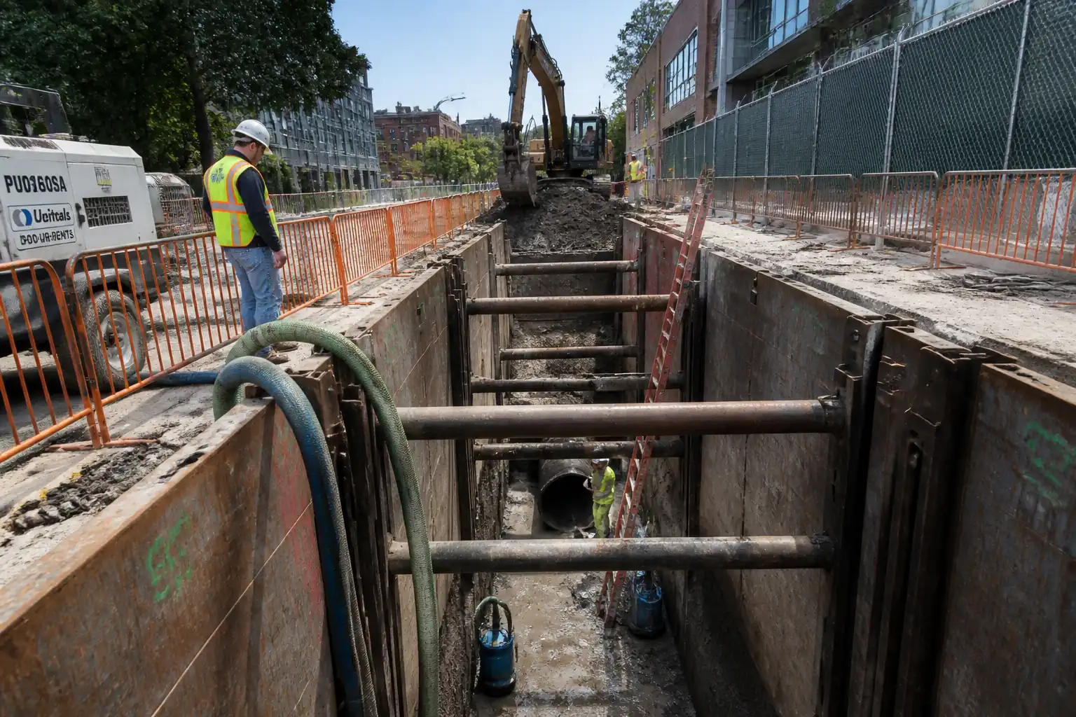
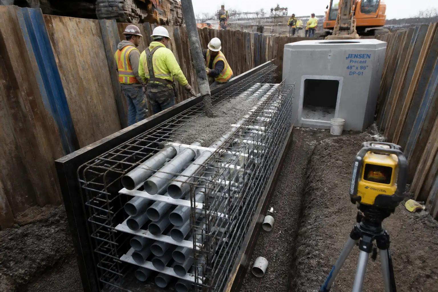
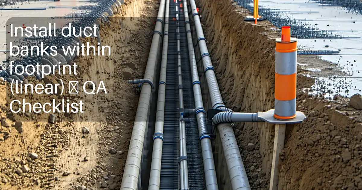
- Setting out of common trench alignment, width, and invert levels for utility corridors (power, comms, water, sewer, or multi-duct banks).
- Potholing/trial holes to locate existing underground services and confirm clearances.
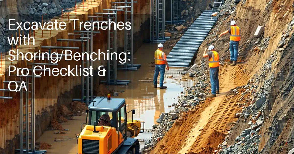
- Excavation by steps/benches where required, with battering or installation of shoring/trench boxes per Temporary Works Design (TWD).
- Groundwater control via sump pumping, wellpoints, or cut-off measures as designed.
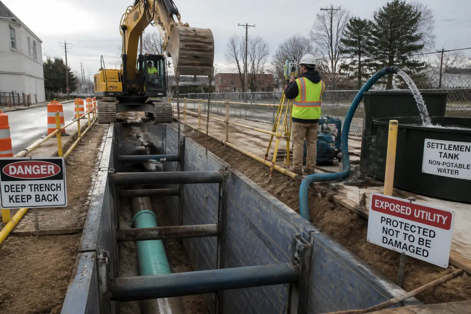
- Protection and support of existing utilities within/adjacent to trench works.
- Formation level trimming, proofing, and base compaction/verification prior to pipe/duct installation.
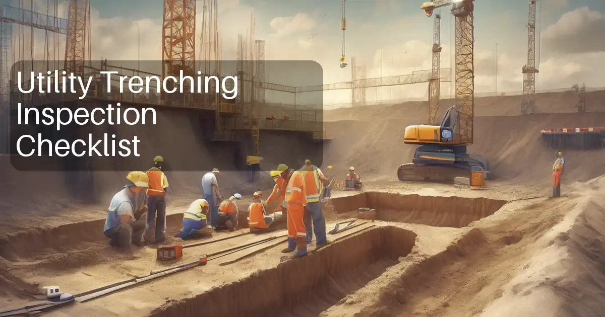
- QA/QC checks of trench width, depth, gradient, and base condition including density/compaction where specified.
Exclusions
- Pipe/duct installation, pressure/leak testing, cable pulling, permanent reinstatement/backfilling beyond formation checks (unless otherwise directed).
Interfaces
- Traffic management, live utility operators, dewatering discharge consents, adjacent structure protection, and environmental constraints.
Key Acceptance Targets [Verify per project specifications]
- Trench width: pipe/duct OD + bedding + working space; typical tolerance +50 mm / -0 mm from minimum design width.
- Formation level tolerance: -0 / +20 mm; longitudinal gradient within ±0.1% or ±10 mm over 10 m.
- Base condition: firm, non-pumping, free of soft spots; compaction to ≥95% MDD (ASTM D698) where granular blinding/bedding is specified.
- Side stability: batter angle or shoring per TWD; no sloughing or raveling at time of inspection.
References
| Document Type | Reference / Number | Revision | Notes |
|---|---|---|---|
| BS EN 1997-1 Eurocode 7: Geotechnical design – General rules (for excavation stability, groundwater, bearing) | Apply design approach and partial factors as per project geotechnical design [Verify]. | ||
| BS 6031: Code of practice for earthworks (excavation practice, moisture, compaction, slope stability) | |||
| BS EN 1610: Construction and testing of drains and sewers (trench widths, bedding, compaction, testing) | Use for utility trenches serving pipelines/duct banks where applicable [Verify]. | ||
| BS 5975: Temporary works procedures and the permissible stress design of falsework (TWC/TWS roles; temp works) | Temporary works procedure and approvals for trench support. | ||
| ASTM D698 / D1557: Laboratory compaction tests (Standard/Modified Proctor) | Define MDD for field density targets [Verify]. | ||
| ASTM D6938: In-place density and moisture (nuclear gauge); ASTM D1556/D2167 as alternatives | Field density/MC verification for formation/bedding/backfill [Verify]. | ||
| BS 1377 series: Methods of test for soils for civil engineering purposes | Classification; moisture; density; CBR as required. | ||
| ISO 9001, ISO 14001, ISO 45001 (Quality, Environmental, and OH&S management systems) | Management framework [Verify per project]. | ||
| Local legislation: excavation safety, dewatering and discharge permits, traffic management [Verify per local regulations] |
Responsibilities
| Role | Responsibility | Name / Party |
|---|---|---|
| PM | Project Manager | Contractor |
| CM | Construction Manager / Site Agent | Contractor |
| TWC | Temporary Works Coordinator (TWC) | Contractor |
| Designer | Temporary Works Designer (TWD) | Specialist |
| Survey | Senior Surveyor / Site Engineer | Contractor |
| HSE | HSE Manager / Safety Officer | Contractor |
| QAQC | QA/QC Engineer | Contractor |
| Utilities | Utility Coordinator | Contractor |
| Dewatering | Dewatering Specialist / Supervisor | Specialist |
| Engineer | Engineer/Employer’s Representative | Engineer |
Resources
| Resource Type | Description | Quantity | Remarks |
|---|---|---|---|
| Personnel | Site Agent, General Foreman | As per workfronts [Verify] | |
| Personnel | 360° excavator operators (certified) | Per shift plan | |
| Personnel | Plant and vehicle marshals | 1 per machine in congested areas | |
| Personnel | Senior Surveyor + Assistant | 1 team per active alignment | |
| Personnel | Pump operator, pipefitter | As designed [Verify] | |
| Personnel | CAT & Genny competent personnel; vacuum excavation crew (if used) | As required |
Materials
| Material | Specification / Grade | Quantity | Remarks |
|---|---|---|---|
| Bedding sand/aggregate | Grading, LA abrasion, fines content per spec | ||
| Selected granular fill | 95–98% MDD (ASTM D698/D1557) as specified [Verify] | ||
| Non-woven geotextile | EN ISO 10319 tensile; EN ISO 11058 permittivity [Verify] | ||
| Steel trench boxes/sheet piles/walers/struts | Per approved TWD | ||
| Warning tape and tracer wire | Color-coded per utility/authority [Verify] | ||
| Concrete blinding | C20/25 nominal [Verify] |
Equipment
| Equipment | Capacity / Type | Quantity | Inspection Required |
|---|---|---|---|
| 13–30 t excavators | Daily plant inspections | ||
| 0.5–2 t | Pre-use checks | ||
| Survey kit | Calibration per QA plan | ||
| Detection equipment | Function checks | ||
| Vac-truck/unit | Operator certification | ||
| Pumps 2–6 in.; flow 20–60 m3/h [Verify] | Daily logs; discharge permit | ||
| Support systems | Pre-use and daily inspection by competent person | ||
| Monitors | Calibration certificates |
Prerequisites
Approvals & Permits
- Approved Method Statement, Risk Assessment, and ITP.
- Permit to Dig/Excavate including utility owner clearances and isolation where required.
- Approved Temporary Works Design (TWD) and Permit-to-Load/Excavate issued by TWC.
- Dewatering/discharge consent and method (sump, wellpoint, treatment) approved.
- Traffic Management Plan approved where works impact carriageways/footways.
Information & Surveys
- Latest IFC drawings, coordinated utility layout, and clash risk register.
- Underground utility records reviewed; on-site utility detection (CAT & Genny, GPR where needed) completed and marked out.
- Pre-condition survey of adjacent structures/pavements; monitoring plan if within influence zone [Verify].
- Geotechnical baseline: soil type, groundwater levels, allowable temporary side slopes, and bearing verified from report [Verify].
Resources & Readiness
- Calibrations current for survey instruments, gas detectors, and density gauges.
- Competence/authorizations checked for operators, banksmen, dewatering personnel.
- Emergency plan briefed (utility strike, flooding, collapse); rescue equipment available.
- Materials available: trench support, pumps/hoses, geotextile (if needed), bedding/blinding (if specified).
- Weather forecast reviewed; heavy rain contingency in place.
Method Sequence
| Step | Activity | Description | Responsibility | Inspection / Hold Point |
|---|---|---|---|---|
| 1 | Pre-start HSE and coordination | Conduct task briefing/Toolbox Talk, review RA/MS, confirm permits, and mark exclusion zones. | Site Supervisor / HSE | Permit to Dig check; TWD & dewatering approvals present |
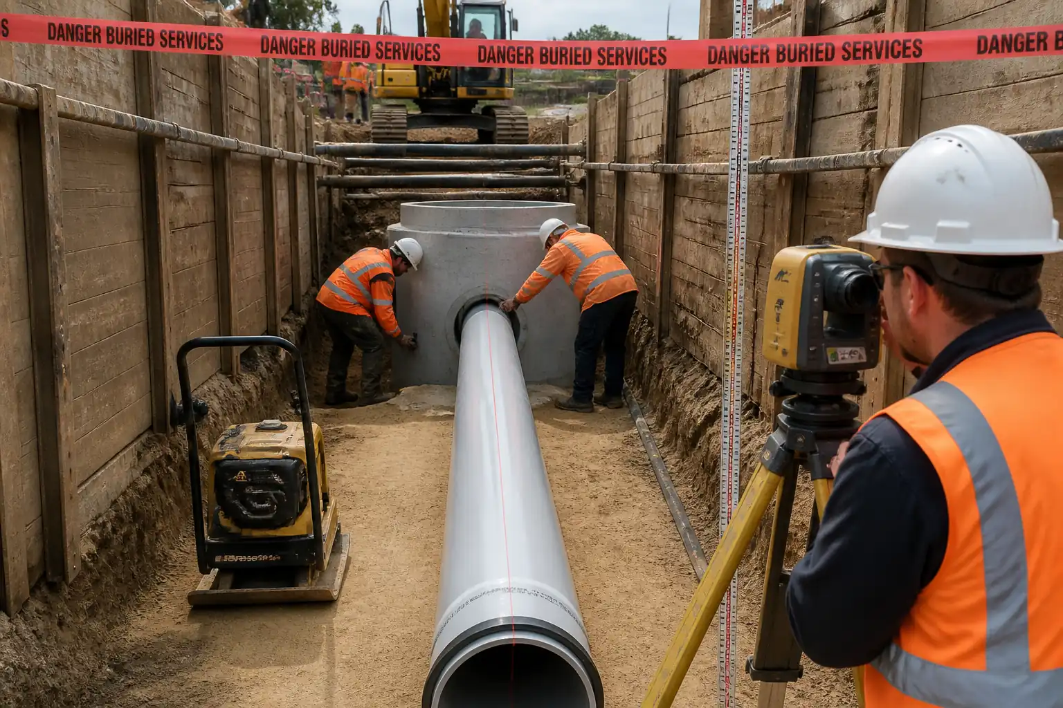
| 2 | Setting out | Set out trench centerline/offsets, invert levels, and hold points using total station/laser. | Surveyor / Site Engineer | Independent check by QA/QC |
| 3 | Utility detection and potholing | Scan with CAT & Genny/GPR; pothole by vacuum excavation or hand-dig to expose utilities. | Utility Coordinator / Supervisor | Witness by Engineer (as required) |
| 4 | Initial excavation to safe depth | Excavate in layers keeping stand-off from services; maintain safe slope or temporary edge restraint. | Excavator Operator / Supervisor | Supervisor checks soil behavior and stability |
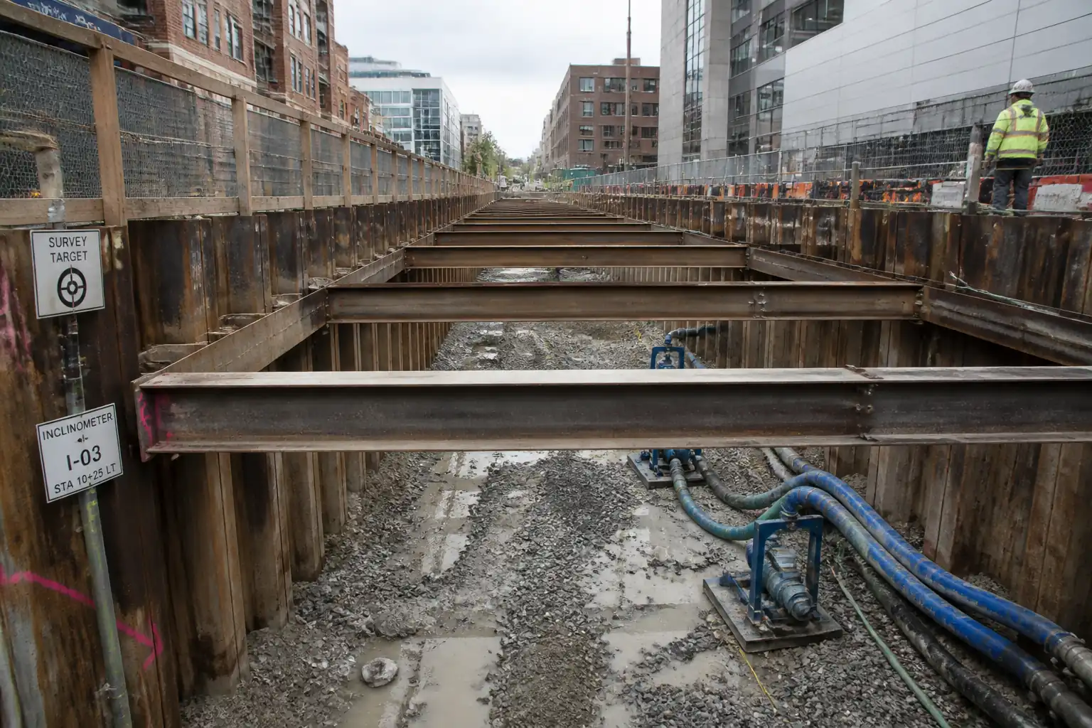
| 5 | Install trench support or batter | Install trench boxes/sheeting/struts or cut batter to TWD; advance sequentially with excavation (leapfrog boxes). | TWC/Supervisor | Inspection by competent person each shift and after events (rain, vibration) |
| 6 | Groundwater control | Install sumps, wellpoints, and pumps as designed; discharge via settlement tank/silt bag. | Dewatering Specialist | Water level monitoring; discharge visual turbidity check |
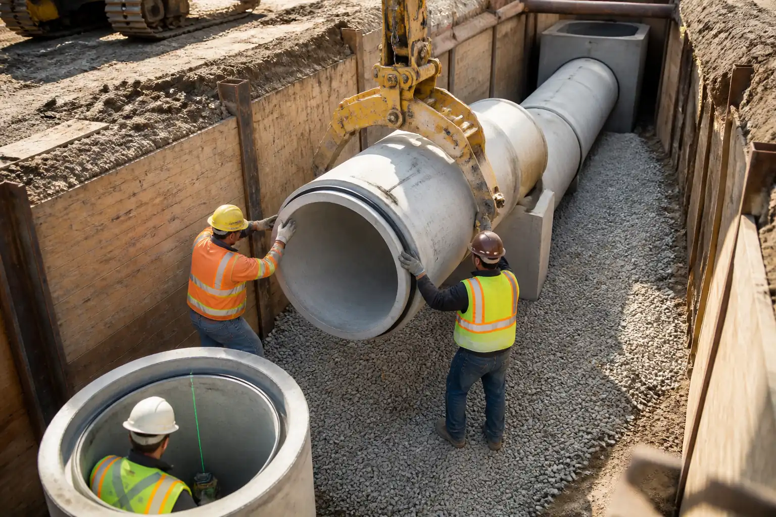
| 7 | Service protection/support | Provide physical protection, bridging, or sling support to crossing/adjacent services. | Utility Coordinator / Supervisor | Verify supports installed per utility owner guidance |
| 8 | Final excavation and trimming | Excavate to formation allowing for bedding thickness; trim and level base; remove loose/soft spots. | Supervisor / Operator / Site Engineer | Engineer inspection prior to compaction/bedding |
| 9 | Formation proofing/compaction | Compact formation or blinding layer as specified using appropriate compaction equipment in lifts. | Supervisor / QA/QC | QA witness density testing |
| 10 | Geotextile (if required) | Place geotextile to separate soft subgrade and bedding; overlap seams per spec. | Supervisor | Visual witness |
| 11 | Pre-handover QA/QC | Confirm trench geometry and base compaction; handover to pipe/duct team. | QA/QC Engineer / Site Engineer | Engineer hold point prior to installation |
Health, Safety and Environment (HSE) – Task-Specific Safety Controls
Principal Hazards and Controls
1) Underground utility strike (electric, gas, fiber, water)
- Consequence: Electrocution, explosion, flooding, service outage.
- Engineering/procedural control: Permit to Dig; review latest utility maps; CAT & Genny and GPR where indicated; mark services; pothole by vacuum or hand to positively identify within 1.5 m of work; impose no-go zones and mechanical standoff distances; use insulated tools near LV cables; coordinate with asset owners.
- Required PPE: Dielectric gloves when appropriate, safety boots, eye protection, arc-rated PPE if specified by utility.
- Collective measure: Physical barriers around exposed utilities; insulated matting; lock-out/tag-out where authorized.
- Inspection/permit/supervision: Permit to Dig signed daily; competent utility locator; Engineer/utility owner witness for critical crossings [Verify per project HSE plan and local regulations].
2) Trench collapse/sidewall instability
- Consequence: Burial/asphyxiation, serious injury/fatality.
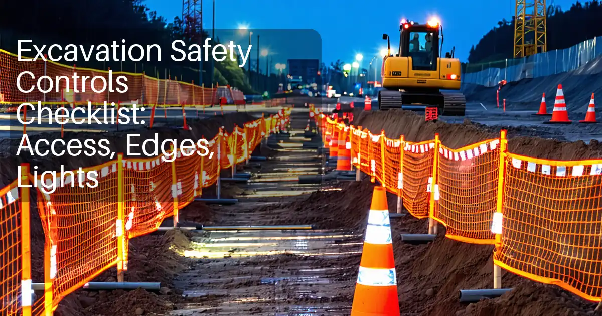
- Engineering/procedural control: TWD-led shoring or compliant battering; no entry >1.2 m deep without protection; install support from top and advance with excavation; maintain groundwater level below formation; daily inspections by competent person and after rain/vibration; keep surcharge and plant ≥0.5–1.0 m from edge [Verify].
- Required PPE: Hard hat, boots, gloves; harness only where part of a rescue plan (not for fall arrest into trench).
- Collective measure: Trench shields/boxes; edge protection (guardrails) and stop blocks for plant.
- Inspection/permit/supervision: Temporary Works inspections logged; Permit-to-Excavate updated; HSE walkdowns.
3) Plant–pedestrian interface and struck-by hazards
- Consequence: Crush injuries/fatality.
- Engineering/procedural control: Segregated walkways; banksman for all reversing; 360° cameras/alarms; designated loading zones; radio comms; lift plans for lifting activities; exclusion zones around swing radius.
- Required PPE: Hi-vis, helmet, safety footwear, gloves, eye protection.
- Collective measure: Physical barriers, traffic cones, signage; gatemen controlling entry.
- Inspection/permit/supervision: Daily plant checks; lifting permits; banksman competence verification.
4) Groundwater ingress/flooding
- Consequence: Instability, drowning risk, equipment damage, pollution.
- Engineering/procedural control: Sumps/wellpoints per design; standby pump; automatic level controls; emergency egress; stop-work trigger if inflow exceeds capacity.
- Required PPE: Wellington/chemical-resistant boots, gloves, lifejackets where deep water possible.
- Collective measure: Pump redundancy; protected power supplies; non-return valves; secured discharge hoses.
- Inspection/permit/supervision: Dewatering logs; discharge consent compliance; supervision by specialist.
5) Hazardous atmospheres (sewer corridors, organic soils)
- Consequence: Asphyxiation/toxicity.
- Engineering/procedural control: Gas test before entry and continuous monitoring (O2/H2S/CO/CH4); forced ventilation if needed; classify as confined space if criteria met and follow permit regime.
- Required PPE: Gas detector, escape set if required, gloves, eye protection.
- Collective measure: Ventilation fans; rescue tripod if classified confined space.
- Inspection/permit/supervision: Confined Space Permit and standby attendant [Verify per local regulations].
6) Spoil heap collapse/edge overloading
- Consequence: Material fall-in, trench collapse.
- Engineering/procedural control: Place spoil ≥0.5–1.0 m from edge [Verify]; height below edge protection; bench spoil; manage rainwater run-off.
- Required PPE: Standard PPE, dust masks as needed.
- Collective measure: Toe boards/edge rails; bunding to deflect run-off.
- Inspection/permit/supervision: Supervisor checks each shift; after heavy rain.
7) Noise, vibration, and dust
- Consequence: Hearing loss, nuisance, respiratory irritation, structure effects.
- Engineering/procedural control: Fit mufflers; limit hours; water spray for dust; vibration monitoring near sensitive assets; select low-vibration methods.
- Required PPE: Hearing protection (SNR per assessment), FFP2/FFP3 dust mask when cutting/backfilling.
- Collective measure: Acoustic barriers; wheel-wash and road sweepers.
- Inspection/permit/supervision: Noise/vibration logs where required; environmental permit conditions complied.
8) Manual handling and access/egress
- Consequence: Musculoskeletal injury, falls.
- Engineering/procedural control: Use mechanical aids; team lifts; ladders secured with 3 m max travel distance to a ladder; maintain 1 m ladder projection above surface; safe walkways.
- Required PPE: Gloves with good grip, boots with ankle support.
- Collective measure: Gantries or steps where feasible.
- Inspection/permit/supervision: Supervisor checks; good housekeeping audits.
9) Traffic interface (roadways)
- Consequence: Collision with public/users.
- Engineering/procedural control: Approved Traffic Management Plan; signage to local standards; temporary barriers; night lighting; speed control.
- Required PPE: Hi-vis class 3 for live carriageway works.
- Collective measure: Vehicle restraint systems; crash cushions where required.
- Inspection/permit/supervision: Permit/authority approvals; daily TM inspections.
Environmental Controls
Controls and Good Practice
- Groundwater and silty discharge: Use sumps/wellpoints with settlement tanks or silt bags; target discharge turbidity per consent [Verify]; route to approved outfall; avoid scour at outlet with energy dissipation.
- Contaminated water/soil: Screen for contamination indicators (odour, sheen); sample if suspected; segregate and dispose via licensed facility; maintain spill kits; refuel >15 m from watercourses where practicable [Verify].
- Dust: Water sprays; cover stockpiles; limit drop heights; wheel-wash at site exit; street sweeping as needed.
- Noise/vibration: Schedule noisy works within permitted hours; use acoustic screens; track vibration at sensitive receptors and stop if trigger exceeded [Verify].
- Waste: Segregate soils (reusable vs. waste); manage geotextile offcuts, shoring timber/steel, and general waste; maintain waste transfer notes.
- Ecology/archaeology: Stop-work and notify if finds encountered; protect trees with RPAs; avoid dewatering drawdown near wetlands without assessment [Verify].
- Resource efficiency: Plan excavation to minimize overbreak; reuse suitable excavated materials where allowed; maintain plant to reduce fuel burn and emissions.
- Emergencies: Spill response plan; containment booms for water discharge if needed; report per EMS and authority requirements.
Quality Assurance / Quality Control
Inspection & Test Strategy
-
Hold/ Witness Points:
1) After potholing and service confirmation (Witness/Hold where critical).
2) After installation of first bay of trench support or confirmation of batter (Hold for deep trenches per TWD).
3) At formation level prior to compaction/bedding (Hold).
4) Prior to pipe/duct installation (Hold). -
Testing Frequencies [Verify per project specifications]:
- Field density/moisture: Min. 1 test per 50 m per layer (or per 200 m² of trench base), each material type and lift.
- Geometry checks: Width/level/gradient every 10–20 m and at changes in alignment or section.
-
Groundwater discharge quality (if required): Turbidity pH/others per consent.
-
Acceptance Criteria [Verify per project specifications]:
- Trench width: Not less than design minimum; typically +50/-0 mm tolerance.
- Formation level: -0/+20 mm; longitudinal gradient within ±0.1% or ±10 mm over 10 m.
- Compaction: ≥95% MDD (ASTM D698) unless otherwise stated; moisture within ±2% of OMC for cohesive fills.
-
Stability: No raveling; shoring/batter conforms to TWD and shows no distress.
-
Documentation & Records:
- ITP checklist; formation approval; density test reports; survey/as-setout and pre-installation as-built; dewatering logs; permits; photos.
- Calibration certificates for survey kit, density gauges, gas detectors.
-
NCR and corrective action process for out-of-tolerance items.
-
Survey Controls:
- Closed-loop check at start/end of shift for critical inverts; laser level/pipe laser verification.
-
Independent survey check once per workfront per day [Verify].
-
Materials Verification:
-
Bedding/backfill delivery tickets, compliance certificates; on-site visual grading check and moisture condition.
-
Handover:
- Signed formation and geometry acceptance prior to release to pipe/duct installation team.
Attachments
Required Appendices/Attachments
- Approved Temporary Works Design (calculations and drawings) and Permit-to-Load/Excavate.
- Dewatering Plan and discharge consent, including treatment details and monitoring requirements.
- Traffic Management Plan and authority approvals.
- Utility maps, potholing logs, and exposure photos; utility owner agreements/permits.
- Survey control report, calibration certificates (survey kit, gas detectors, density gauges).
- QA/QC ITP checklists, formation inspection forms, field density reports, NCRs (if any).
- HSE documents: Risk Assessment, Emergency Response Plan, daily inspection checklists.
- Environmental Method Statement (if separate), waste management plan, spill response plan.
- Drawings: IFC trench sections and typical details; setting out drawings; as-built updates after potholing.
This content is a read-only public reference. Download or customize to get an editable version.
ITP preview
The first inspection activities from the linked ITP for Method Statement: Common Trench Excavation for Utility Corridors:
| Activity | Inspection / Test | Acceptance Criteria | Responsibility | Record |
|---|---|---|---|---|
| Permits and pre-start controls | Verify RA/MS approval, Permit to Dig, TWD approval, TM plan | All approvals current; workforce briefed; exclusion zones set. | PM / HSE / Supervisor | Pre-start checklist; permits filed |
| Setting out | Alignment/level check against IFC | Chainage/offset ±20 mm; invert stakes ±5 mm | Surveyor / QA/QC | Set-out records; independent check sheet |
| Utility detection & potholing | Scan results; exposed utility survey; photos | Utilities positively identified; clearances adequate or mitigation agreed. | Utility Coordinator / Engineer | Potholing logs; marked-up drawings |
Showing 3 of 10 inspection activities. View full ITP →
Related Inspection and Test Plan
An Inspection and Test Plan (ITP) is available for Method Statement: Common Trench Excavation for Utility Corridors. The ITP defines the inspection activities, acceptance criteria, hold and witness points, responsible parties, and records required to verify the work described in this method statement.
View the Method Statement: Common Trench Excavation for Utility Corridors ITP →Frequently asked questions
Continue with related Quollnet resources connected to this method statement.