
Inspection and Test Plan for Method Statement: Trial Pit Excavation and Utility Exposure Works
AI-assisted inspection and test plan connected to a method statement, with PDF and Excel export.
More than a static template
Unlike a downloadable Word or PDF template, this ITP is an AI-assisted editable starting point directly connected to its method statement. Every inspection activity, hold point, and acceptance criterion is structured and ready to adapt to your project.
- AI-assisted customization — Tailor inspection activities and acceptance criteria to your specific project scope.
- Linked method statement — This ITP is connected to the corresponding method statement describing the work sequence.
- Multiple export formats — Download as a formatted PDF or editable Excel spreadsheet.
- Editable starting point, not a final document — Review and verify all content against your project specifications and standards before use.
What you can customize
When you save this ITP to your account, every inspection row becomes editable. You can add, remove, or modify:
- Inspection activity — Description of what is being inspected.
- Inspection type — Hold point (H), Witness point (W), Review (R), or Monitor (M).
- Responsibility — Contractor, subcontractor, engineer, or client.
- Frequency — How often the inspection occurs.
- Acceptance criteria — Referenced standard or specification requirement.
- Records — Forms, test reports, or checklists required as evidence.
Why this ITP is used
To verify that trial pits and utility exposures are executed safely and to specification, ensuring accurate utility data for subsequent works.
Who uses this inspection and test plan
Site managers, utility locators, QA/QC engineers, surveyors, HSE officers, and client representatives.
When this ITP is prepared and submitted
Before and during trial pit excavation and until reinstatement and documentation are complete.
Who receives or approves this ITP
Client/Engineer and, where required, utility owners or highway authorities.
Inspection scope
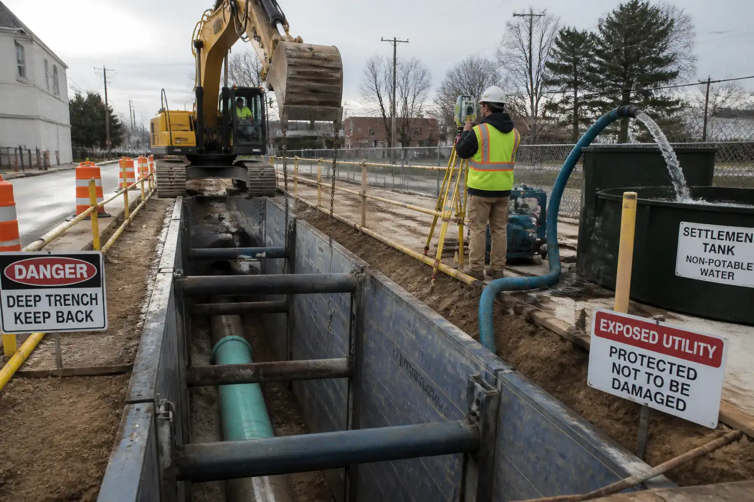
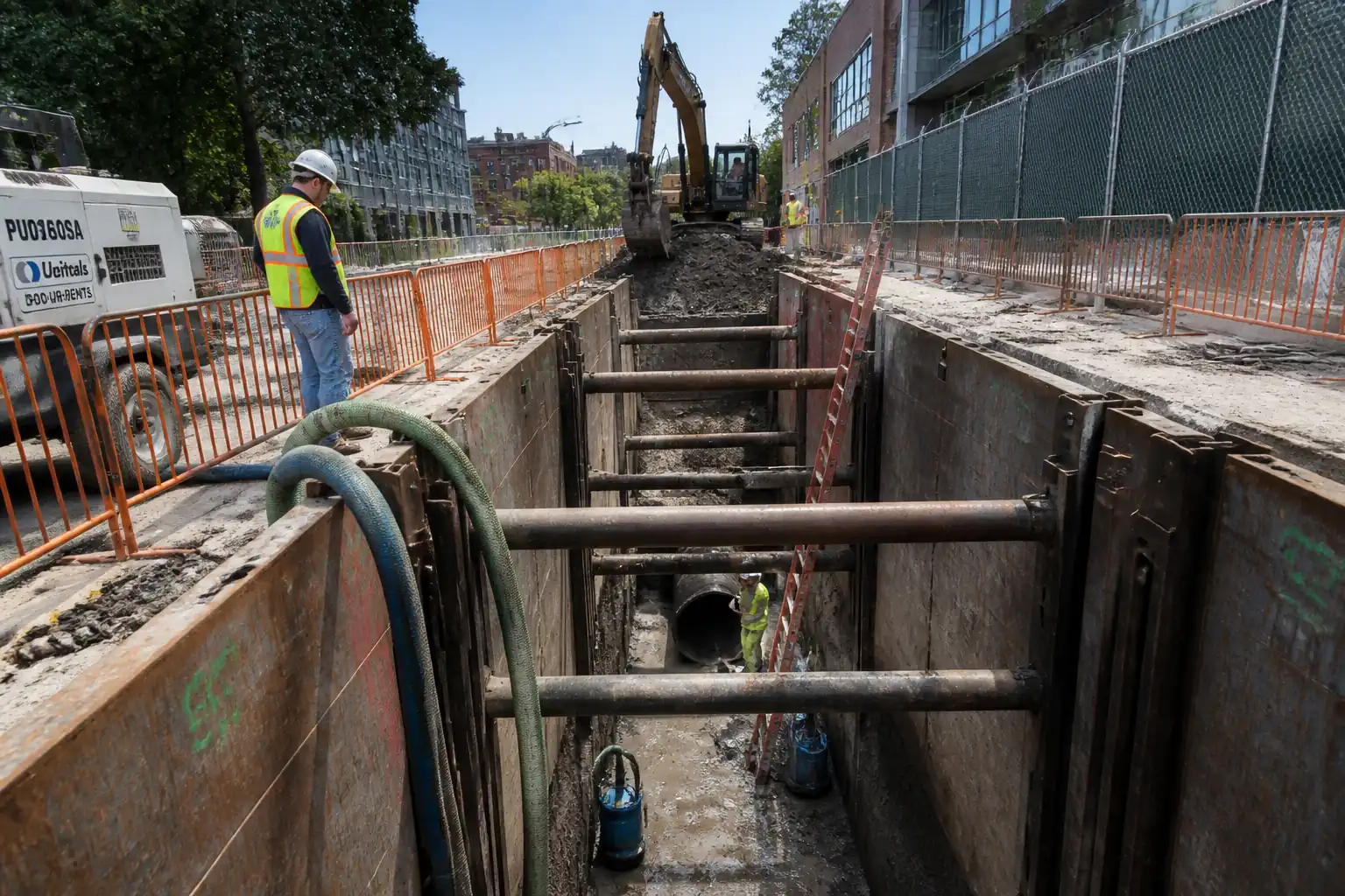
Permits, CAT/GPR scans, set-out, excavation controls, temporary support, exposure verification, survey, backfill compaction, reinstatement, and records.
Typical hold, witness, and review points
Temporary support installation (Hold), surface reinstatement (Witness/Hold as specified), initial excavation near utilities (Witness), final survey (Witness).
Typical inspection records
Permit-to-Dig, scan reports, daily inspections, exposure photos, as-built survey, density test reports, reinstatement checklists, calibration certificates.
Important approval note
This ITP is an AI-assisted editable starting point, not a pre-approved document. Before use on any project, all inspection activities, hold points, and acceptance criteria must be reviewed and approved by the relevant parties (superintendent, principal contractor, or client representative) in accordance with your contract and project quality plan.
Always verify acceptance criteria against your applicable drawings, specifications, and regulatory requirements. Hold points must be confirmed with the relevant authority before work proceeds past that point.
Inspection and test plan
| Activity | Inspection / Test | Acceptance Criteria | Responsibility | Record |
|---|---|---|---|---|
| Permit-to-Dig and pre-start briefing | Permit validation; attendance register | Valid permits; personnel briefed and signed | Site Manager / HSE | Permit copy; briefing sheets |
| Utility records collation and review | Records completeness check | All utility owners contacted; latest records received | Project Manager / Utility Locator | Records log; mark-up |
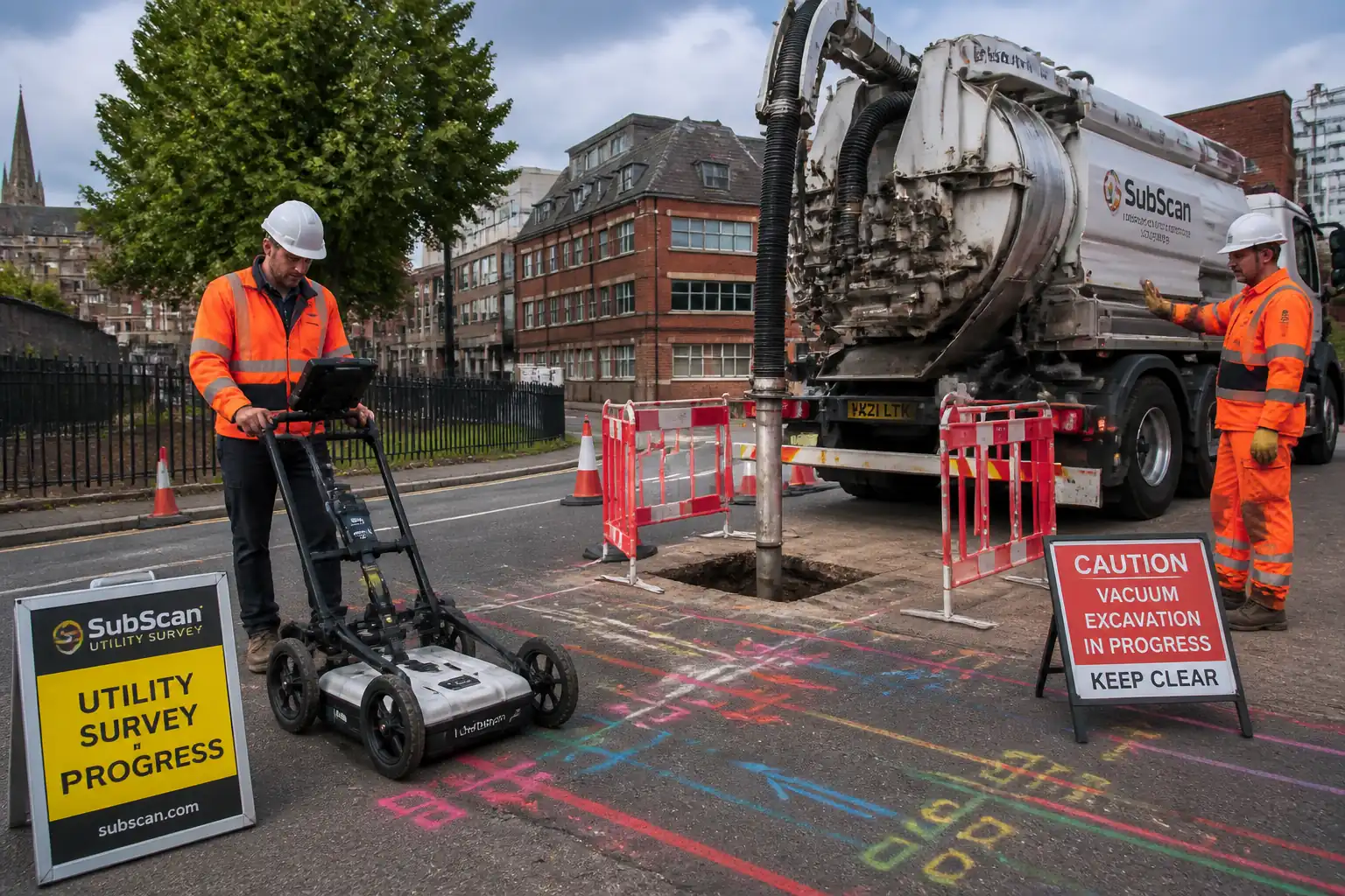
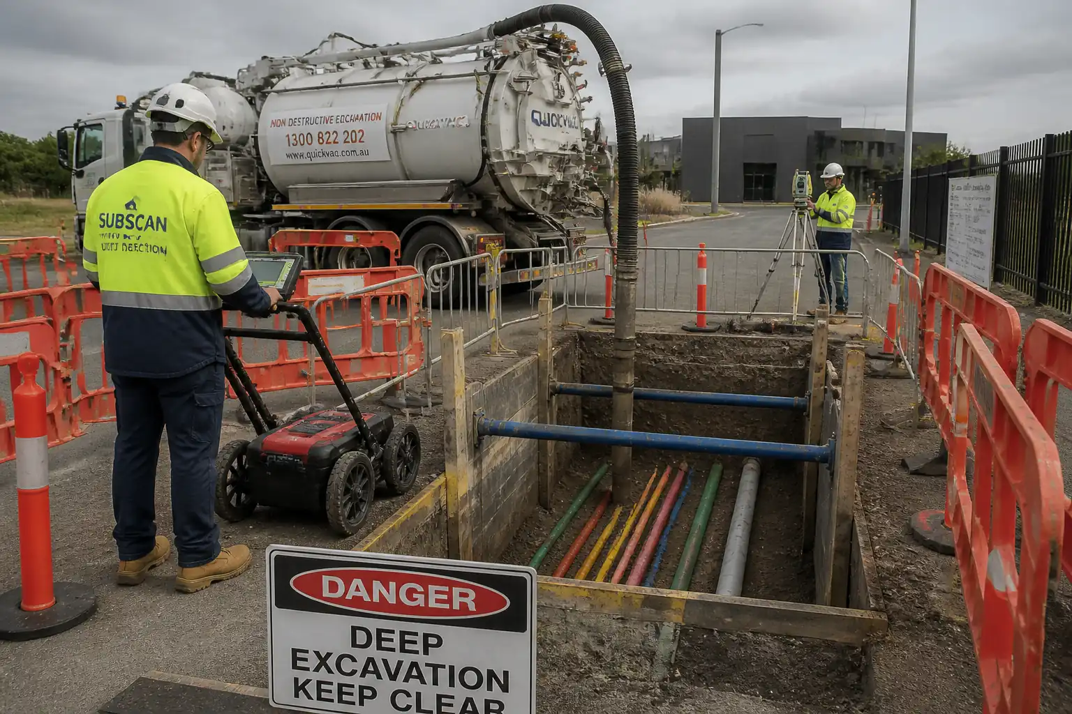
| On-site CAT/GPR scanning and mark-up | Function/bump tests; scan coverage check | PAS 128 QL-B achieved where practicable; all services marked | Utility Locator | Scan report; calibration certs; photos |
| Setting-out of trial pit | Coordinate check vs control | Set-out within ±20 mm [Verify] | Surveyor | Set-out report; photos |
| Surface cutting/removal | Visual; hot work permit if applicable | Clean edges; no damage to adjacent structures | Crew Lead | Daily log; photos |
| Initial excavation (mechanical within limits) | Depth/offset spot checks | No mechanical dig within 500 mm lateral/300 mm vertical of suspected services [Verify] | Operator / Supervisor | Daily log |
| Hand/vacuum excavation near utilities | Visual | Utilities exposed without damage; min 300 mm length visible | Crew Lead | Exposure checklist; photos |
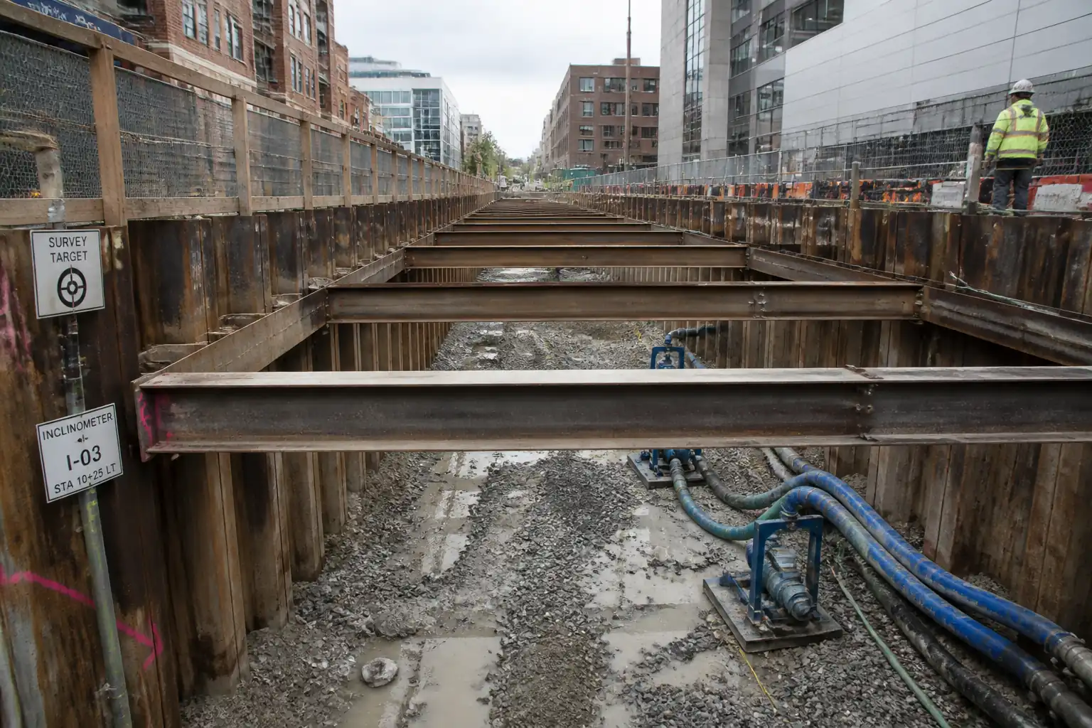
| Temporary support installation | Support inspection sheet | Support per TWD; safe access/egress provided | TWC/TWD / Supervisor | TWC approval; inspection record |
| Atmospheric testing (if required) | Gas readings recorded | O2 19.5–23.5%; LEL <10%; H2S/CO within limits [Verify] | HSE / Crew Lead | Gas test log |
| Utility identification and survey | Measurement check; closure check | Survey accuracy ±10–25 mm [Verify]; metadata complete | Surveyor / QA | As-built points; utility log; photos |
| Backfill and compaction | In-situ density per lot | 95% MDD trafficked; 90–93% MDD footways [Verify] | QA / Crew Lead | Density test results; layer records |
| Warning tape installation | Visual | Correct color; 150–300 mm above crown [Verify] | Supervisor | Photo record |
| Surface reinstatement | Thickness/level/finish checks | Layer thickness -5/+10 mm; surface ±10 mm; finish matches | QA / Supervisor | Reinstatement checklist; tickets |
| Close-out documentation | Document completeness | All records submitted and approved | Project Manager / QA | Handover pack; as-built; ITP; photos |
This table is a read-only public reference. Download the PDF or Excel version, or customize this ITP to edit it for your project.
Frequently asked questions
Related method statement
This Inspection and Test Plan is associated with the Method Statement: Trial Pit Excavation and Utility Exposure Works method statement, which describes the step-by-step construction sequence, resources, materials, equipment, safety controls, and environmental controls for this activity.
View the Method Statement: Trial Pit Excavation and Utility Exposure Works method statement →Continue with related inspection, method statement, article, and checklist resources.