Inspection and Test Plan for Method Statement: Deep Excavation Temporary Support Works Near Existing Structures and Services
AI-assisted inspection and test plan connected to a method statement, with PDF and Excel export.
More than a static template
Unlike a downloadable Word or PDF template, this ITP is an AI-assisted editable starting point directly connected to its method statement. Every inspection activity, hold point, and acceptance criterion is structured and ready to adapt to your project.
- AI-assisted customization — Tailor inspection activities and acceptance criteria to your specific project scope.
- Linked method statement — This ITP is connected to the corresponding method statement describing the work sequence.
- Multiple export formats — Download as a formatted PDF or editable Excel spreadsheet.
- Editable starting point, not a final document — Review and verify all content against your project specifications and standards before use.
What you can customize
When you save this ITP to your account, every inspection row becomes editable. You can add, remove, or modify:
- Inspection activity — Description of what is being inspected.
- Inspection type — Hold point (H), Witness point (W), Review (R), or Monitor (M).
- Responsibility — Contractor, subcontractor, engineer, or client.
- Frequency — How often the inspection occurs.
- Acceptance criteria — Referenced standard or specification requirement.
- Records — Forms, test reports, or checklists required as evidence.
Why this ITP is used
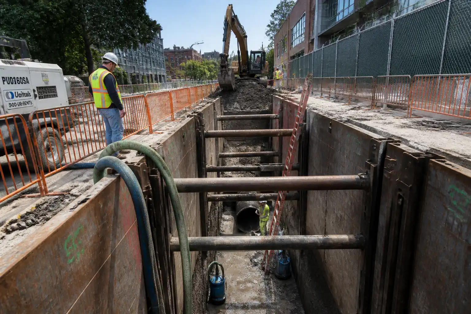
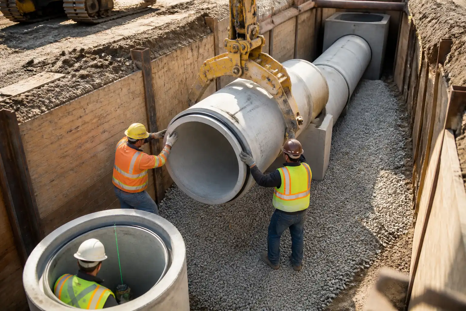
To assure that temporary works for deep excavation are installed, tested, and monitored to specification and risk is controlled at critical stages.
Who uses this inspection and test plan
Contractor’s site team, TWC, QA/QC, geotechnical engineer, specialists, and the Engineer/Employer’s Representative.
When this ITP is prepared and submitted
From pre-construction (PTD, baseline) through each excavation stage, shoring/anchor installation, to backfilling and demobilization.
Who receives or approves this ITP
The ITP is usually submitted to the client representative, consultant, resident engineer, or project management consultant for review and approval before the related work activity starts.
Inspection scope
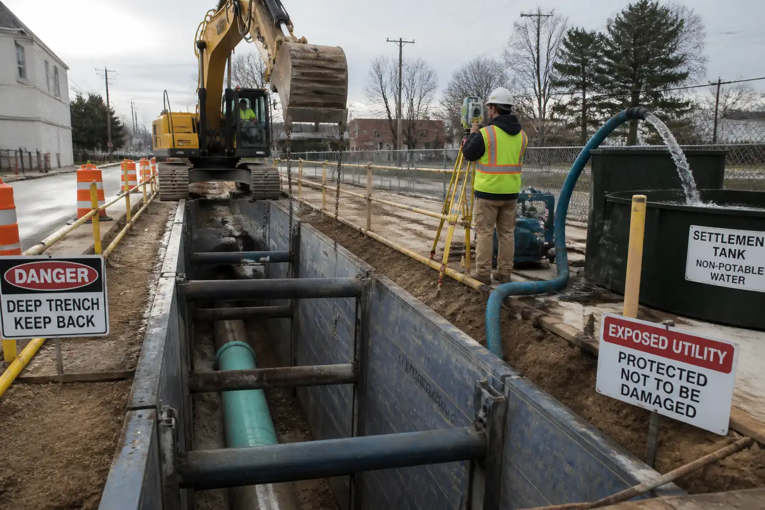
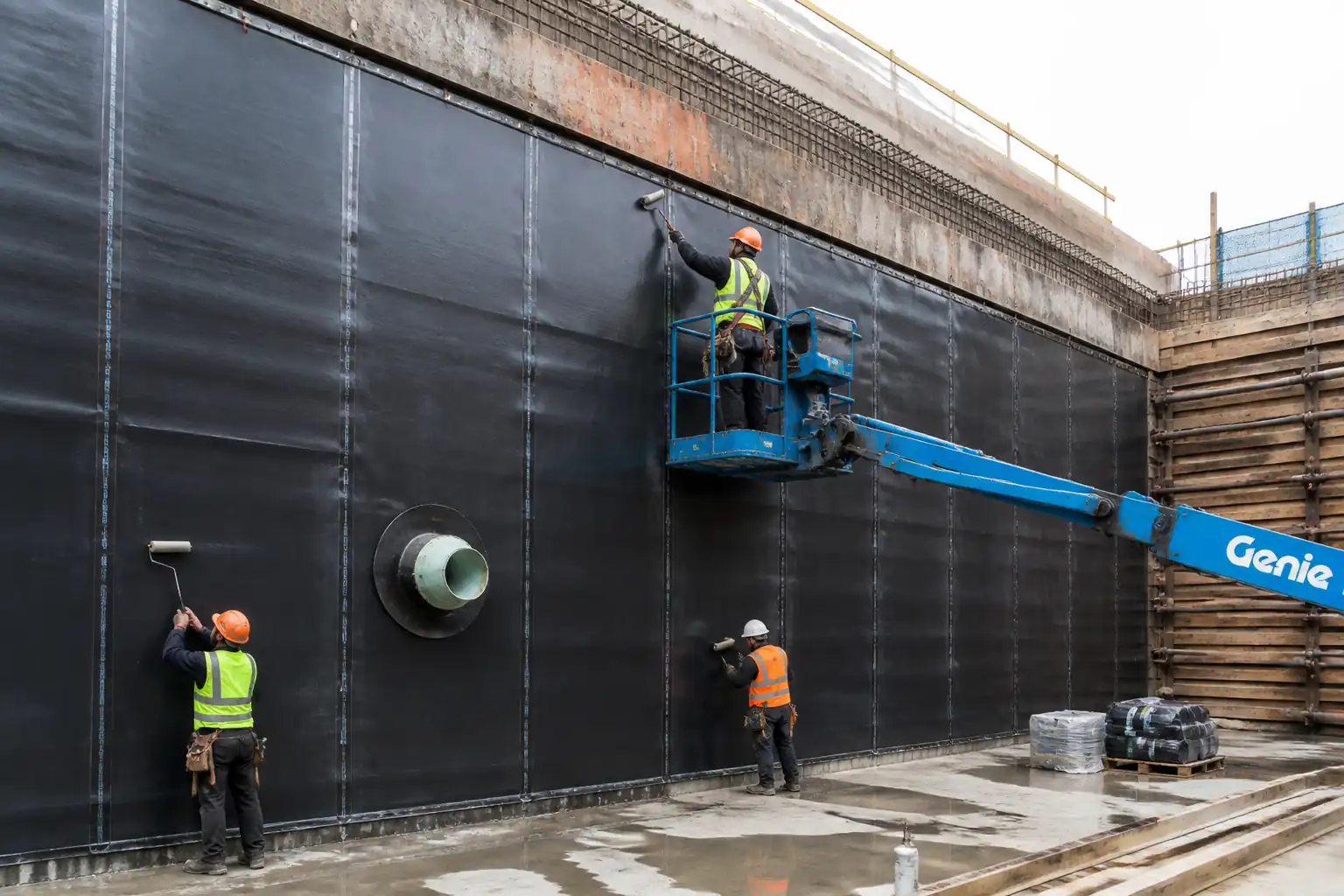
Utilities clearance, instrumentation, dewatering, embedded wall installation, staged excavation, strut/anchor works, base stability, environmental discharge, and support removal.
Typical hold, witness, and review points
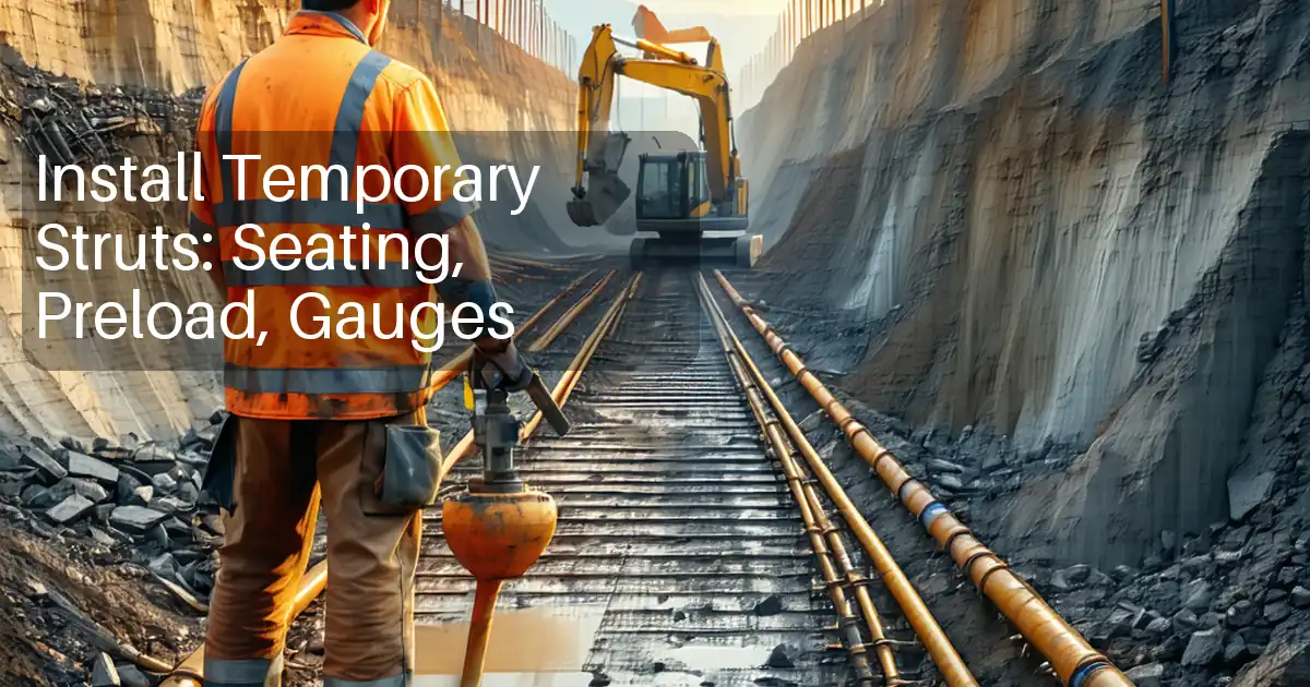
HP-1 PTD; HP-2 instrumentation baseline; HP-3 dewatering pump test; HP-4 wall alignment/toe; HP-5/7 staged levels; HP-6 strut preload; HP-8 anchor testing; HP-9 base stability; HP-10 removal.
Typical inspection records
PTD pack, piling/anchor logs, NDT reports, torque/preload sheets, monitoring snapshots, pump test data, discharge samples, base check certificate, as-builts.
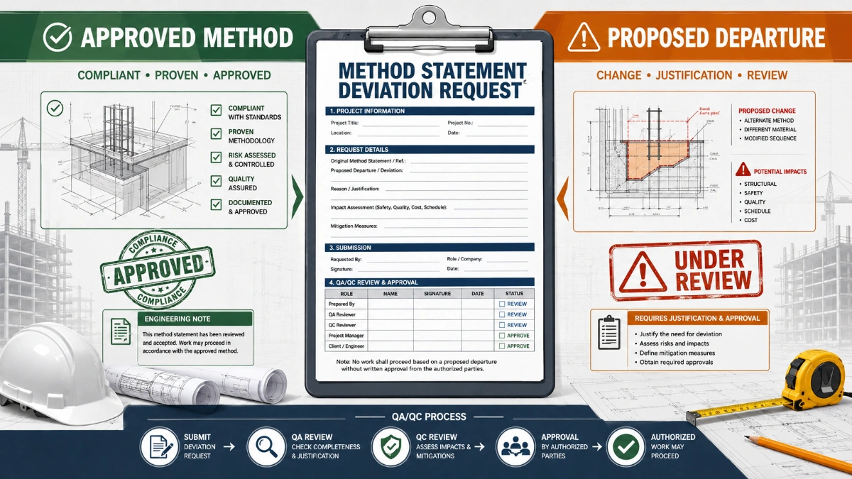
Important approval note
This ITP is an AI-assisted editable starting point, not a pre-approved document. Before use on any project, all inspection activities, hold points, and acceptance criteria must be reviewed and approved by the relevant parties (superintendent, principal contractor, or client representative) in accordance with your contract and project quality plan.
Always verify acceptance criteria against your applicable drawings, specifications, and regulatory requirements. Hold points must be confirmed with the relevant authority before work proceeds past that point.
Inspection and test plan
| Activity | Inspection / Test | Acceptance Criteria | Responsibility | Record |
|---|---|---|---|---|
| Permit-to-Dig and utility verification (HP-1) | GPR/EML scans; trial pit records; PTD form | All utilities located/marked; method of protection/isolation approved; no mechanical excavation within 1 m of live services [Verify] | Utilities Coordinator / QA-QC / Engineer | PTD pack, trial pit photos, as-found survey |
| Instrumentation installation and baseline (HP-2) | Installation check; calibration certs; baseline readings | Locations/depths per design; baseline stable (variation within instrument precision over 48–72 h) [Verify] | Monitoring Specialist / Engineer | Instrumentation as-built, baseline report |
| Dewatering system and pump test (HP-3) | Drawdown verification; flow measurement; discharge sampling | Water level ≥1.0–1.5 m below base; stable drawdown without excessive settlement; discharge within permit limits [Verify] | Dewatering Manager / Geotechnical Engineer | Pump test log; lab results; approval memo |
| Embedded wall installation (HP-4) | Depth logs; plumbness checks; weld inspections | Verticality ≤1:100–1:200; position ±25–50 mm; toe as design; welds to ISO 5817 specified level; NDT results acceptable | Piling Supervisor / QA-QC / Engineer | Piling logs; weld NDT; as-built survey |
| Stage excavation to support level (HP-5/7) | Survey levels; inclinometer/settlement; piezometers | Stage level within ±50 mm; monitoring within green/amber thresholds; geotechnical stability acceptable | Site Engineer / TWC / Geotechnical Engineer | Stage inspection checklist; monitoring snapshot |
| Waler/strut installation and preload (HP-6) | Bolt torques; preload readings; NDT of critical welds | Bolt torque within spec; preload 80–110% target with ≤5% relaxation in 1 h; weld NDT acceptable | Steelwork Supervisor / QA-QC | Torque sheets; preload logs; NDT reports |
| Ground anchor testing and lock-off (HP-8) | Suitability/performance/proof tests; grout tests | Meets EN 1537 requirements; creep within limit; elongation within ±10%; lock-off ±5%; grout strength ≥ specified | Anchor Specialist / Engineer | Anchor test certs; grout cube results |
| Base formation and stability (HP-9) | Survey; piezometers; visual for boils/heave | FS against heave ≥1.3–1.5; water level ≥1.0–1.5 m below base; formation level ±20 mm | Geotechnical Engineer / Site Engineer | Base check certificate; survey |
| Environmental discharge monitoring | TSS, pH, hydrocarbons | Within discharge consent/permit [Verify] | Environmental Manager / Dewatering Manager | Lab certificates; log sheets |
| Removal of temporary supports/backfill (HP-10) | Confirmation of permanent works capacity/strength; compaction tests | Engineer approval; backfill compaction ≥95% MDD [Verify] | TWC / Engineer | Approval memo; compaction results |
This table is a read-only public reference. Download the PDF or Excel version, or customize this ITP to edit it for your project.
Frequently asked questions
Related method statement
This Inspection and Test Plan is associated with the Method Statement: Deep Excavation Temporary Support Works Near Existing Structures and Services method statement, which describes the step-by-step construction sequence, resources, materials, equipment, safety controls, and environmental controls for this activity.
View the Method Statement: Deep Excavation Temporary Support Works Near Existing Structures and Services method statement →Continue with related inspection, method statement, article, and checklist resources.