Method Statement: Deep Trench Excavation and Shoring Installation for Stormwater Mainlines – Method Statement
AI-assisted method statement with matching ITP, PDF download, and Excel export.
More than a static template
Unlike a downloadable Word or PDF template, this method statement is an AI-assisted editable starting point connected directly to a matching Inspection and Test Plan. Every section is structured, project-adaptable, and ready to export.
- AI-assisted drafting — Customize every section with AI for your specific project scope.
- Linked ITP — A matching inspection and test plan is generated alongside the method statement.
- Multiple export formats — Download as a formatted PDF or editable Excel spreadsheet.
- Editable starting point, not a final document — Review, verify, and adjust all content against your project requirements before use.
Static template vs. Quollnet workflow
| Feature | Static template | Quollnet |
|---|---|---|
| Project-specific content | Manual fill-in required | AI-assisted customization |
| Linked ITP | Separate document, no link | Matching ITP included |
| Export formats | Usually PDF only | PDF and Excel |
| Structured sections | Free-form layout | 13 standardized sections |
| Saved to your account | Local file only | Cloud-saved, reusable |
| Content accuracy | You verify everything | AI-assisted, you still verify |
| Cost | Often free but time-intensive | Free to customize and download |
What you can customize
When you save this method statement to your account, every section becomes editable. The following 13 sections are included:
- Scope — Defines the activity and its boundaries.
- References — Standards, specifications, and drawings.
- Responsibilities — Roles and accountabilities.
- Resources — Labour, plant, and equipment summary.
- Materials — Materials and compliance requirements.
- Equipment — Tools and equipment details.
- Prerequisites — Hold points and pre-conditions.
- Method sequence — Step-by-step construction sequence.
- Safety controls — HSE risk controls and PPE.
- Environmental controls — Environmental mitigation measures.
- QA/QC — Quality inspection and test requirements.
- ITP — Inspection and Test Plan table (has its own page).
- Attachments — Referenced drawings and documentation.
Why this method statement is used
This method statement is used to define and communicate the approved procedure for carrying out method statement: deep trench excavation and shoring installation for stormwater mainlines on site. It ensures the work is planned in advance, the correct resources and controls are in place, and all personnel understand responsibilities, sequence, quality requirements, and safety controls before work begins. It aligns site execution with the documented scope and acceptance expectations.
Who uses this method statement
This method statement is used by contractors, site supervisors, project engineers, QA/QC engineers, HSE officers, consultants, and client representatives. It serves as a shared reference for planning, execution, supervision, inspection, and approval of the activity on site.
When it is prepared and submitted
The method statement is prepared before the work activity starts and submitted as part of the pre-construction documentation package for review and approval.
Who reviews or approves it
The method statement is usually submitted to the client representative, consultant, resident engineer, or project management consultant for review and approval before the work commences.
Important approval note
This method statement is an AI-assisted editable starting point, not a pre-approved document. Before use on any project, all content must be reviewed and approved by the relevant parties (superintendent, principal contractor, or client representative) in accordance with your contract and project quality plan.
For example: if your specification requires a departure from a referenced standard, that departure must be documented and approved separately — this method statement will not capture that automatically. Always verify against your applicable drawings, specifications, and regulatory requirements.
Method statement content
Scope
Overview
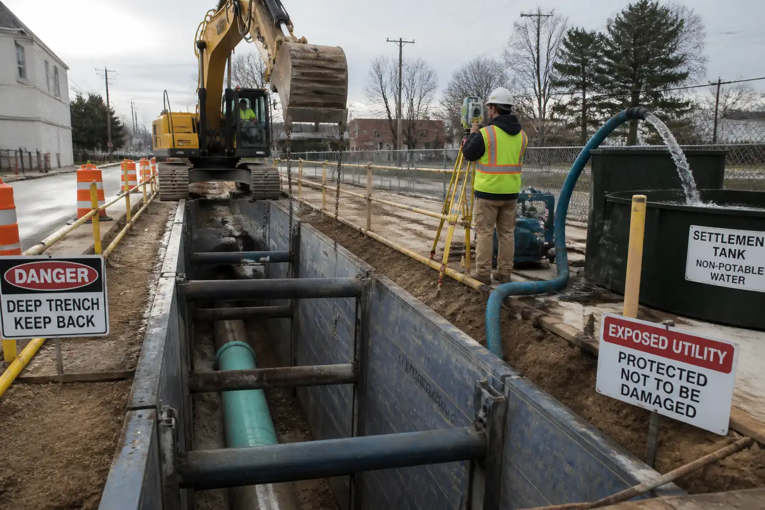
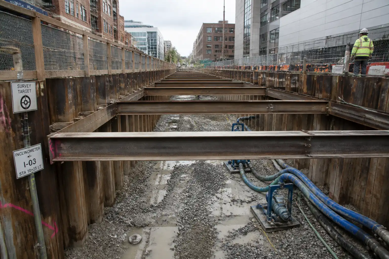
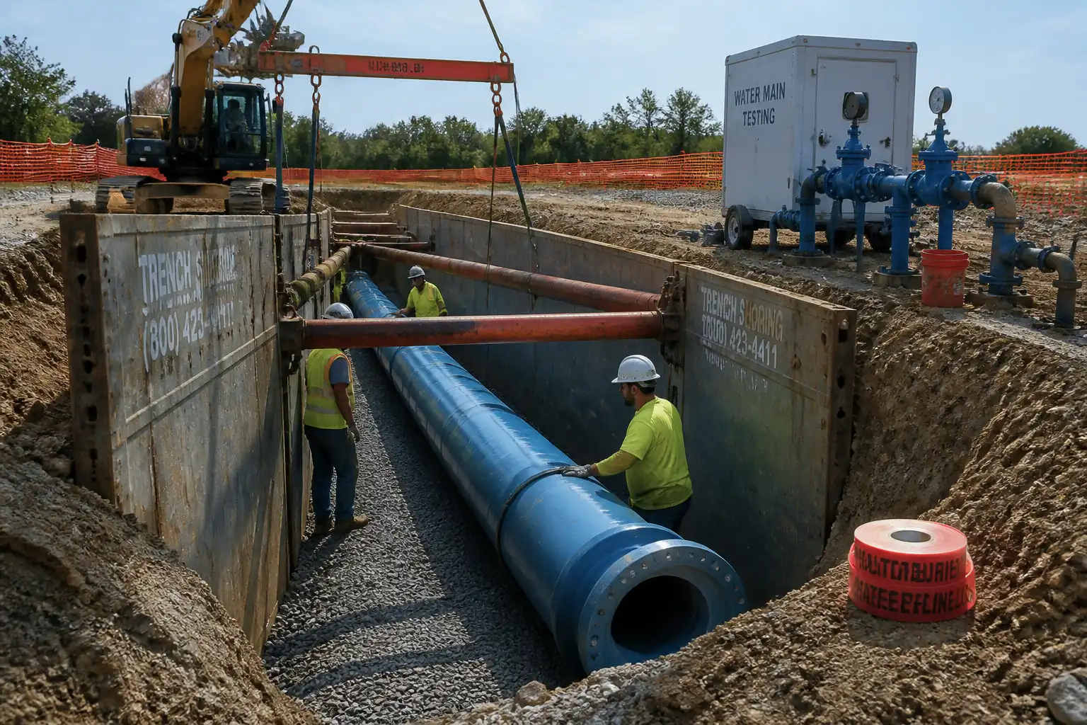
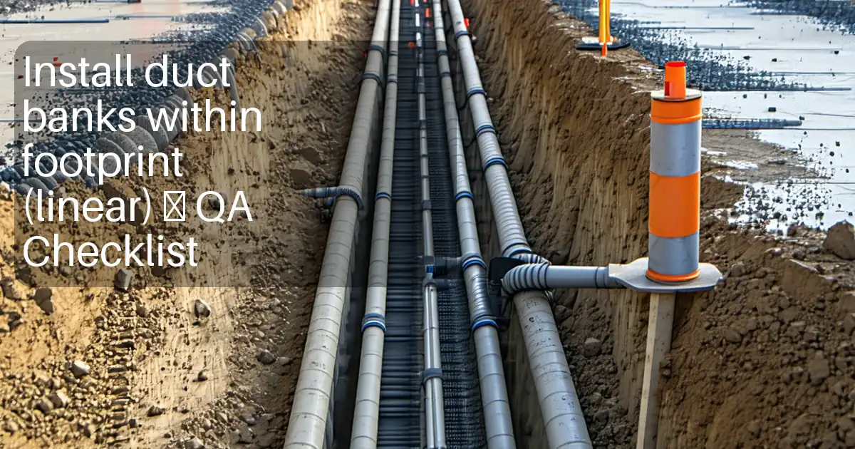
This method statement details the execution of deep trench excavation and temporary shoring for installation of stormwater mainlines, with optional use of slide-rail systems or trench boxes. It addresses utility locating and protection, groundwater control, soil classification, temporary works design and monitoring, trench access/egress, trench backfilling within pipe zone, and associated QA/QC and HSE controls.
Limits of Work
- Trench lengths as per IFC drawings [Verify per project specifications].
- Depths typically 3.0–7.0 m; trench width as required for pipe OD, shoring, and safe working clearance [Verify per project specifications].
- Ground conditions per geotechnical report (cohesive/non-cohesive soils; groundwater expected near/above trench invert in sections).
Key Outputs
- Verified service clearances and pothole records.
- Installed and monitored dewatering system with compliant discharge.
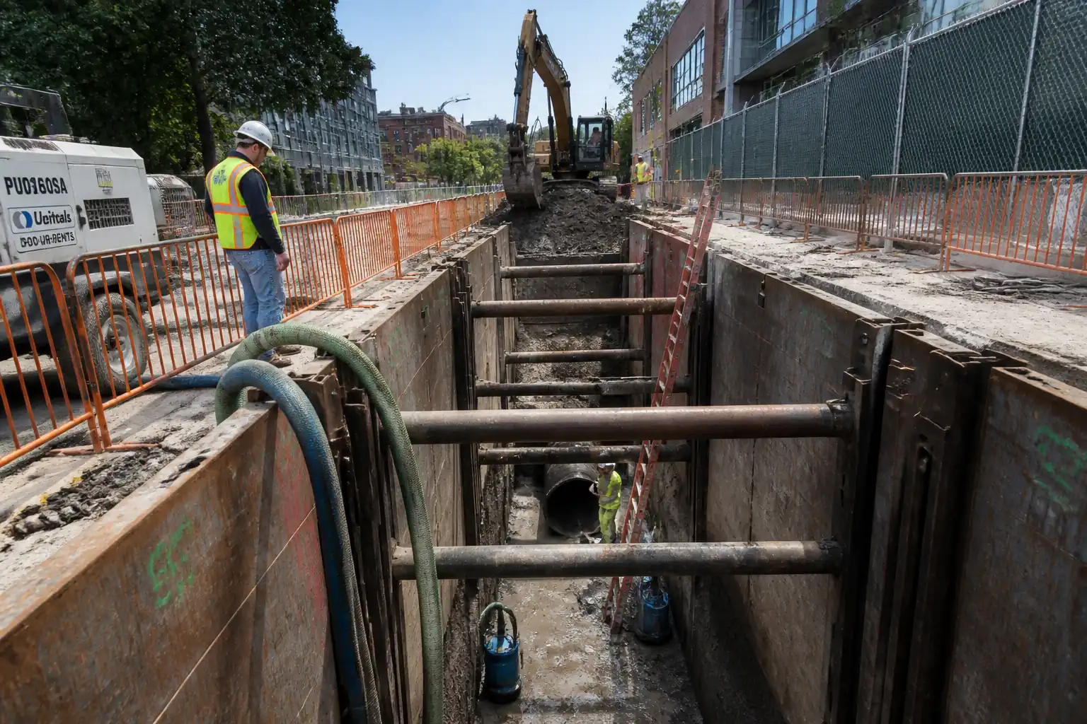
- Installed temporary shoring (slide-rail or trench box) to maintain stable trench.
- Safe access ladders within 7.5 m of all workers and extending ≥1.0 m above surface.
- Verified trench dimensions, levels, and compliance records.
Interfaces/Exclusions
- Interface with pipe-laying crews and manhole construction.
- Traffic management by approved plan.
- Utility isolation/permits by asset owners as needed.
References
| Document Type | Reference / Number | Revision | Notes |
|---|---|---|---|
| Standard | EN 1997-1 | Temporary works design principles for excavations and support [Verify per project specifications]. | |
| Standard | EN 13331 (Parts 1 & 2) [or equivalent national standard] | For trench boxes and slide-rail components [Verify per project specifications]. | |
| Standard | BS 6031 | Excavation, stability, backfill guidance. | |
| Guidance | CIRIA C750 | Wellpoint/deep well design and monitoring. | |
| ASTM | ASTM D2487 | For trench stability and dewatering design inputs. | |
| ASTM | ASTM D698 / ASTM D1557 (or BS 1377) | Basis for field density acceptance. | |
| ASTM | ASTM D6938 | Alternative sand-cone ASTM D1556. | |
| Regulation/Standard | OSHA 29 CFR 1926 Subpart P [or local equivalent — verify] | Trench protection, access/egress, inspections [Verify per project HSE plan and local regulations]. | |
| ISO | ISO 9906 | For dewatering pump performance verification (as applicable). | |
| ISO | ISO 45001 / ISO 14001 | Framework for HSE controls [Verify per project]. |
Responsibilities
| Role | Responsibility | Name / Party |
|---|---|---|
| Project Manager | Project Manager | Contractor |
| TWC | Temporary Works Coordinator (TWC) | Contractor |
| Designer | Temporary Works Designer / Shoring Supplier Engineer | Specialist |
| HSE | HSE Manager / HSE Officer | Contractor |
| Surveyor | Surveyor | Contractor |
| Coordinator | Utility Coordinator | Contractor |
| Site Engineer | Site Engineer / Foreman | Contractor |
| QA/QC | QA/QC Engineer | Contractor |
| AP/Crane Supv/Banksman | Lifting Appointed Person / Crane Supervisor / Banksman | Contractor |
Resources
| Resource Type | Description | Quantity | Remarks |
|---|---|---|---|
| Labour | Foreman, Site Engineer, Excavator Operator(s), Pipe Layer(s) interface, Skilled Workers, Banksman, Pump Technician, HSE Officer, Surveyor, QA/QC Technician | As required | |
| Permits | Excavation permit, Hot work (if any), Dewatering/discharge permit, Traffic management approval, Utility crossing permits |
Materials
| Material | Specification / Grade | Quantity | Remarks |
|---|---|---|---|
| High-strength steel | As per design | ||
Equipment
| Equipment | Capacity / Type | Quantity | Inspection Required |
|---|---|---|---|
| As required | Yes | ||
| Yes | |||
| Yes | |||
| Yes | |||
| Yes | |||
| Yes | |||
| Yes |
Prerequisites
Permits and Approvals
- Approved excavation permit, traffic management plan, and dewatering/discharge permit.
- Temporary Works Design (TWD) for shoring approved by the Engineer; category and independent check defined.
- Utility clearances from all asset owners; isolation/shutdown arranged where required.
Information and Surveys
- Geotechnical data reviewed (soil stratification, permeability, shear strength, groundwater levels).
- Precondition survey of adjacent structures/pavements; baseline settlement/deflection markers installed where needed.
- Service locating completed using GPR/EML and potholing to confirm depths and alignments at all crossings.
- Set-out control established and protected; benchmarks verified.
Method Controls and Planning
- Risk assessment and method briefed to crew (toolbox talks) including rescue plan.
- Lifting plans for shoring components approved; plant access routes verified for bearing capacity.
- Dewatering design (wellpoint spacing, pump sizing, discharge route, monitoring) approved; contingency/standby pumps arranged.
- Materials and equipment inspected; calibration certificates current.
- Weather and flood risk reviewed; stop-work criteria defined for heavy rainfall or water inflow beyond pump capacity.
- Waste management and sediment control measures installed.
Hold/Witness Points
- H1: Utility clearance and pothole verification before excavation.
- H2: Shoring delivery inspection and TWC pre-use inspection.
- W1: Dewatering commissioning and drawdown trial.
- H3: First bay excavation and shoring installation check (pattern approval).
Method Sequence
| Step | Activity | Description | Responsibility | Inspection / Hold Point |
|---|---|---|---|---|
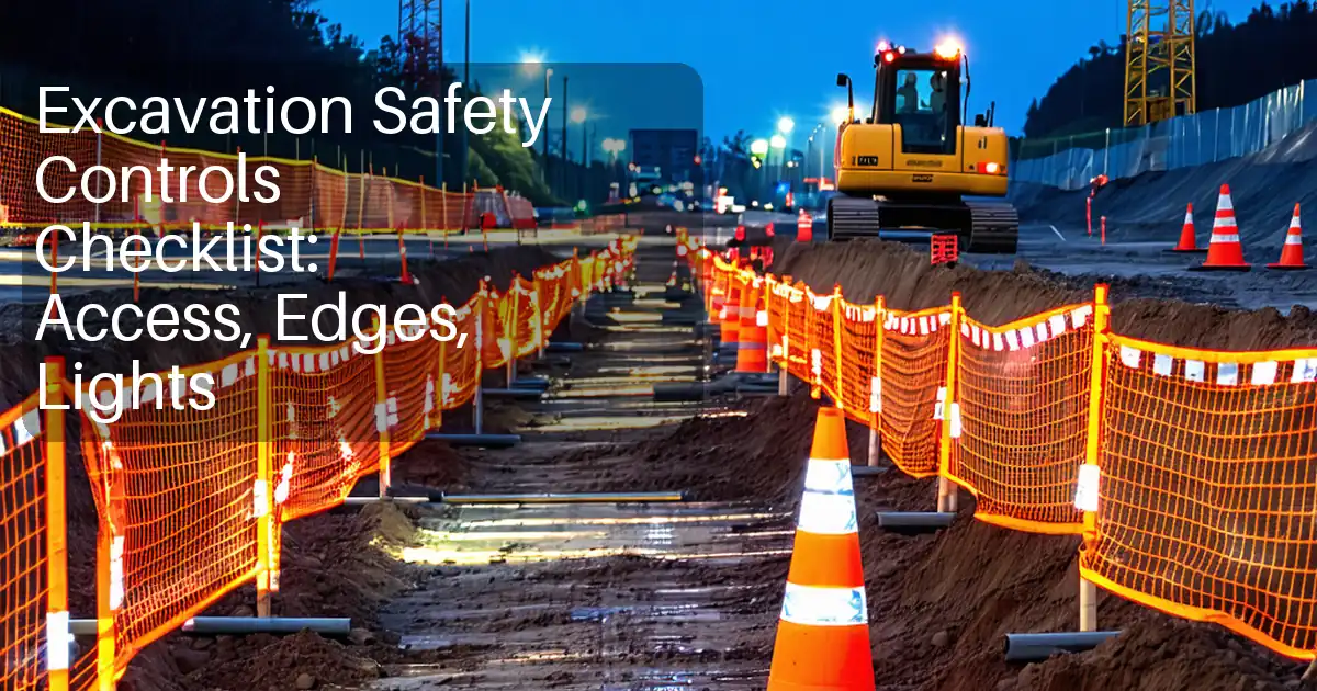
| 1 | Site establishment and traffic control | Install traffic management, barriers, signage, lighting per approved plan; establish exclusion zones and plant routes. | Site Engineer/Foreman | HSE walkdown |
| 2 | Utility locating and potholing | GPR/EML scanning along the alignment; hand or vacuum excavate trial pits at crossings to positively locate services and set protective coverings/slinging points. | Utility Coordinator/Foreman | Hold point H1 |
| 3 | Dewatering installation | Install wellpoints at 1.0–1.5 m spacing or deep wells as designed; header pipe with isolation valves; discharge to settlement tanks and approved outfall with oil booms. | Dewatering Subcontractor | ITP witnessing W1 |
| 4 | Initial excavation (pilot bay) | Excavate first bay to ~0.5–1.0 m depth; trim to shoring footprint; maintain spoil 0.6–1.0 m away from edge with toe boards. | Foreman/Operator | Engineer/TWC check |
| 5 | Shoring installation – slide-rail (option) | Place corner posts and insert panels progressively using dig-and-push method; install spreaders at designed elevations; maintain panel embedment below formation. | Shoring Crew/TWC | Hold point H2/H3 |
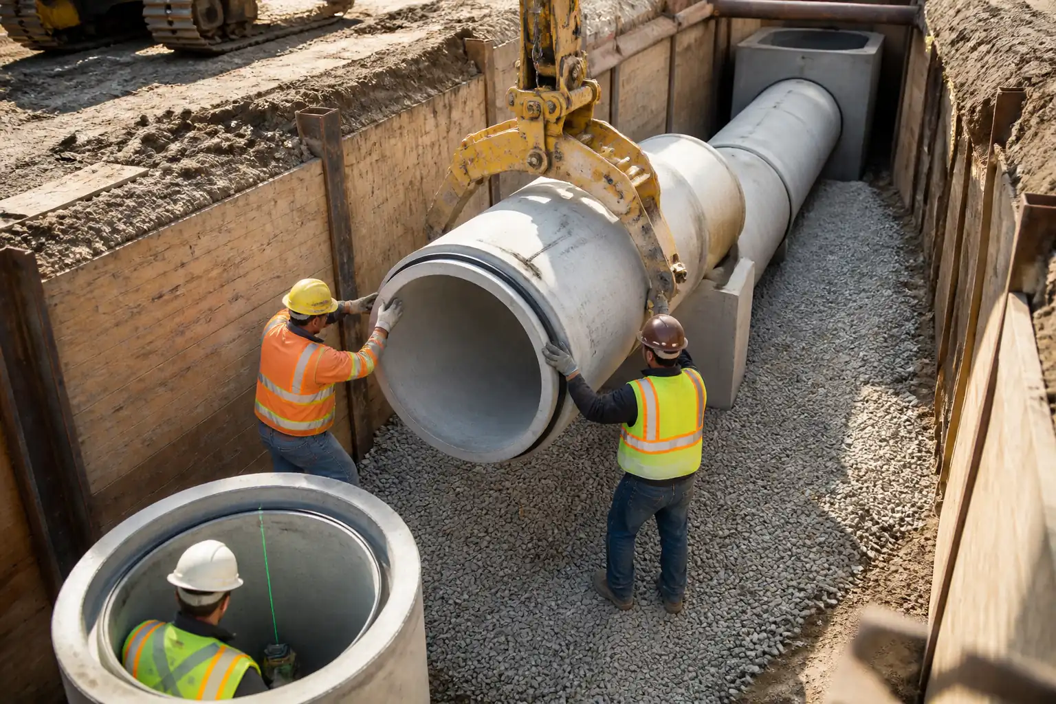
| 6 | Shoring installation – trench box (option) | Lower box using crane/excavator; excavate ahead, advance box progressively keeping shield close to face; set spreaders to maintain width. | Shoring Crew/Banksman | TWC check |
| 7 | Progressive excavation to formation | Excavate in stages (≤1.0 m lifts) with concurrent shoring advancement; maintain access ladders within 7.5 m; manage groundwater inflow. | Foreman/Operator | Shift inspections |
| 8 | Access/egress and edge protection | Install secured ladders extending ≥1.0 m above ground; edge barriers 1.1 m; ladder spacing ≤7.5 m along trench. | Foreman/HSE | HSE inspection |
| 9 | Utility crossings | At crossings, hand-dig within 0.5 m of service; provide bridging/protection mats; reduce excavator forces; install additional local shoring as required. | Foreman/Utility Coordinator | Engineer witness |
| 10 | Formation verification | Survey invert and line using laser/total station; confirm trench width and benching (if any). | Surveyor/QA-QC | ITP hold |
| 11 | Pipe zone bedding (if in scope) | Place bedding layer 100–150 mm; compact with vibratory plate avoiding shoring contact; verify level. | Foreman/QA-QC | ITP witness |
| 12 | Monitoring during works | Daily shoring inspection by competent person; check deflection, spreader loads (visual/strain gauges if specified), ground movement markers, and water levels. | TWC/Engineer | Daily |
| 13 | Backfilling around pipe zone (after pipe installation) | Place sidefill and initial backfill in ≤200–300 mm lifts; compact with suitable equipment avoiding pipe flotation/box contact. | Foreman/QA-QC | ITP witness |
| 14 | Shoring extraction | Extract slide-rails/panels or trench box incrementally while backfilling to avoid voids; ensure no suction on pipe or bedding. | Shoring Crew/Banksman | TWC oversight |
| 15 | Demobilization and reinstatement (temporary) | Remove dewatering after rebound monitoring; cap wells; remove temporary works; tidy site; maintain temporary surface. | Foreman/Dewatering Subcontractor | Final inspection |
Health & Safety Controls
Hazard Controls (Task-Specific)
- Hazard: Undetected underground utilities strike (electric, gas, fiber)
- Consequence: Electrocution, explosion, service outage
- Engineering/Procedural Control: GPR/EML survey, potholing; no mechanical excavation within 1 m until service proven; insulated tools near LV; asset owner permits and supervision for critical crossings; machine slew/height restrictors near overheads.
- PPE: Dielectric gloves (as required), arc-rated clothing near electrical, eye/face protection, safety boots, HV vest
- Collective Measure: Physical barriers and marker tapes; temporary protective mats/bridging over services
-
Inspection/Permit/Supervision: Excavation PTW; utility crossing permit; competent person supervision; daily service location briefings [Verify per project HSE plan and local regulations]
-
Hazard: Trench collapse/shoring failure
- Consequence: Burial/asphyxiation, serious injury/fatality
- Engineering/Procedural Control: TWD-compliant slide-rail/trench box; pre-use inspection; daily competent person inspection; no entry outside protection; exclusion zone; maintain pump capacity; adhere to TARP triggers
- PPE: Helmets with chin strap, gloves, steel-toe boots, eye protection
- Collective Measure: Engineered shoring, edge barriers, spotter control
-
Inspection/Permit/Supervision: TWC inspections before use and after any event (rainfall, impact); recorded daily
-
Hazard: Plant-lifting incidents during shoring placement
- Consequence: Crushing, struck-by, component drop
- Engineering/Procedural Control: Appointed Person lift plan; certified lifting accessories; tag lines; defined exclusion zone; no personnel in trench during suspended loads
- PPE: Helmet, gloves, boots, eye protection, high-vis
- Collective Measure: Barriers and banksman control; radio comms
-
Inspection/Permit/Supervision: Pre-lift checks; LOLER/third-party certs; crane supervisor present
-
Hazard: Falls into excavation
- Consequence: Major injury
- Engineering/Procedural Control: Edge protection 1.1 m, toe boards; controlled access; lighting; crossings with trench plates rated for load
- PPE: Helmets, boots
- Collective Measure: Guardrails and covers
-
Inspection/Permit/Supervision: Daily HSE inspections; after-hours security
-
Hazard: Ingress of water and flooding
- Consequence: Loss of ground, drowning risk, collapse
- Engineering/Procedural Control: Dewatering with standby pumps and high-level alarms; sump management; weather watch; stop-work criteria if inflow exceeds capacity
- PPE: Waterproof boots, gloves; lifejackets if working near open water bodies
- Collective Measure: Emergency egress ladders; escape routes
-
Inspection/Permit/Supervision: Dewatering logs; weekly function test of standby pumps
-
Hazard: Hazardous atmosphere (contaminated ground, H2S in storm sewers)
- Consequence: Poisoning, asphyxiation
- Engineering/Procedural Control: Pre-work ground contamination review; atmospheric testing before entry if indicators present; forced ventilation if required; treat deep, narrow sections as potential confined spaces when criteria met
- PPE: Gas monitor, respiratory protection if authorized
- Collective Measure: Access control and rescue plan
-
Inspection/Permit/Supervision: Confined Space PTW when applicable [Verify per project HSE plan and local regulations]
-
Hazard: Spoil pile instability/rolling objects
- Consequence: Struck-by, edge overload
- Engineering/Procedural Control: Keep spoil ≥0.6–1.0 m from edge; bench spoil; use stop blocks for trucks
- PPE: Helmets, boots
- Collective Measure: Physical edge markers and berms
-
Inspection/Permit/Supervision: Foreman checks each shift
-
Hazard: Noise/vibration from pumps and plant
- Consequence: Hearing loss, nuisance, structural impact
- Engineering/Procedural Control: Acoustic shrouds; limit hours; vibration monitoring near sensitive structures; low-vibration methods
- PPE: Hearing protection
- Collective Measure: Barriers and enclosures
-
Inspection/Permit/Supervision: Noise and vibration logs; compliance with permits
-
Hazard: Slips/trips from hoses, cables, uneven ground
- Consequence: Minor/major injury
- Engineering/Procedural Control: Hose ramps, cable management; housekeeping
- PPE: Boots with good grip
- Collective Measure: Defined walkways
-
Inspection/Permit/Supervision: Daily housekeeping inspection
-
Hazard: Traffic-plant interface
- Consequence: Collision, injury
- Engineering/Procedural Control: One-way plant routes; marshals; plant-person interface plan; reversing alarms and cameras
- PPE: High-vis, helmets, boots
- Collective Measure: Barriers and segregated walkways
-
Inspection/Permit/Supervision: TM inspections and audits by competent person
-
Hazard: Manual handling of drag hoses, panels
- Consequence: Strains/sprains
- Engineering/Procedural Control: Mechanical aids, team lifts, job rotation
- PPE: Gloves, back support if approved
- Collective Measure: Use machinery for moves
- Inspection/Permit/Supervision: Supervisor oversight and training records
General Note: All controls to be verified against the project HSE plan and local regulations.
Environmental Controls
Dewatering and Water Quality
- Provide treatment via settlement tanks/bags and filtration as needed. Target turbidity per permit (e.g., ≤50 NTU) and pH 6.0–9.0 [Verify]. No visible oil sheen; install absorbent booms.
- Discharge only to approved outfalls; install flow meters and log discharge volumes.
- Monitor drawdown to minimize settlement of adjacent assets; adjust pump rates and staging. Implement Trigger Action Response Plan (e.g., Alert: 50% of trigger; Action: 100% trigger) [Verify].
Erosion and Sediment Control
- Perimeter controls: silt fence, fiber rolls, catch basin protection.
- Stabilize stockpiles (covering, distance ≥10 m from drains where possible) and place ≥0.6–1.0 m from trench edge.
- Maintain stabilized access/egress to prevent tracking.
Noise, Dust, and Vibration
- Fit acoustic enclosures on pumps; limit night work where restricted.
- Water spray for dust suppression; wheel wash as needed.
- Monitor vibration where structures are within influence zone; set limits per project/geotechnical guidance [Verify].
Spills and Waste
- Secondary containment for fuel and pumps; spill kits at each pump.
- Segregate wastes; dispose via licensed carriers. No discharge of bentonite/polymer unless permitted.
Ecology and Community
- Protect trees and habitats; no storage within dripline; use root protection boards if crossing.
- Maintain public information signage and complaint log; respond within 24 h.
Permits and Reporting
- Maintain water quality logs, waste transfer notes, noise/vibration monitoring records.
- Stop-work if permit exceedances occur; notify Engineer and regulators as required.
Quality Assurance & Quality Control
Controls and Tolerances
- Trench alignment and invert: tolerance ±10 mm on invert; gradient ±0.1%; alignment ±20 mm [Verify per project specifications].
- Trench width: OD + working clearance + shoring system thickness [Verify].
- Over-excavation: ≤50 mm; if exceeded, backfill with approved material and re-compact.
- Shoring: verticality ≤1/100; spreader levels within ±10 mm; clearances per TWD.
- Access: ladders at ≤7.5 m spacing; extend ≥1.0 m above surface; secured.
Testing and Frequency
- Soil classification: Visual/manual logging to ASTM D2488; confirm against D2487 where lab data available.
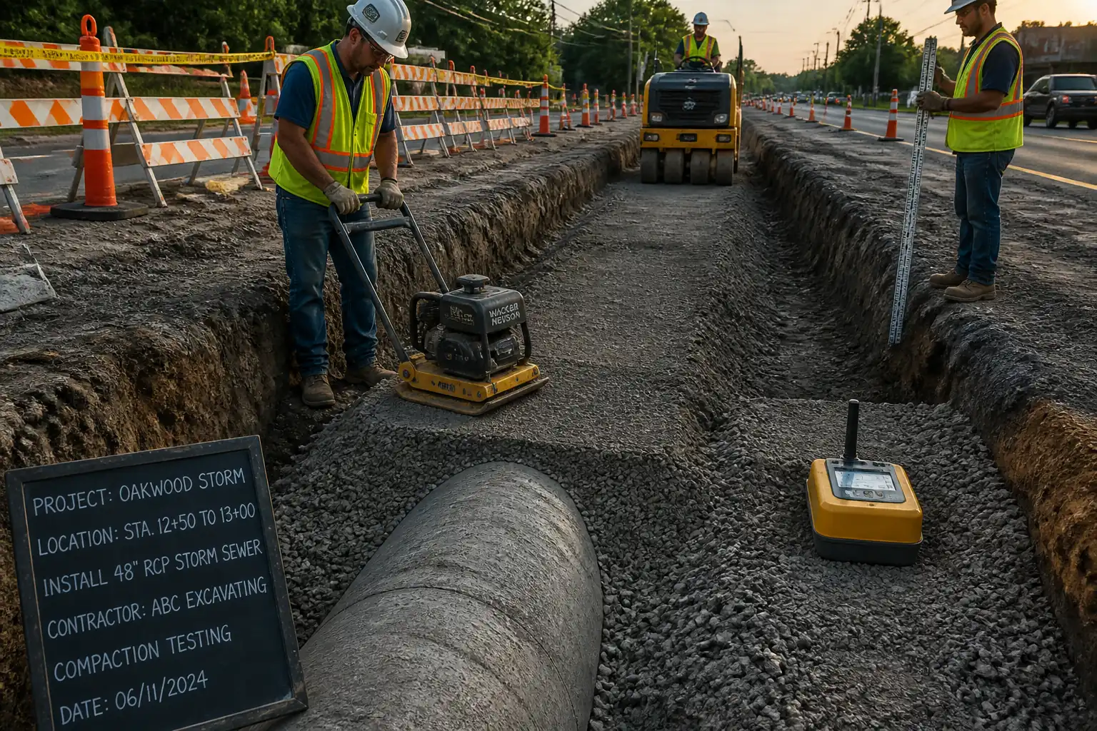
- Compaction: Nuclear density ASTM D6938 (or sand cone). Frequency: 1 test per 50 m of trench per lift, minimum 1 per lift per work area [Verify]. Acceptance: Pipe zone ≥95% MDD (Std Proctor); above-zone ≥98% to subgrade [Verify].
- Water quality: Turbidity and pH at discharge start, then daily; additional tests after rainfall or pump changes [Verify].
- Monitoring: Daily shoring inspection checklist; weekly summary to TWC; settlement/deflection per monitoring plan.
Calibration and Documentation
- Instruments (laser, level, density gauge) with valid calibration (≤6 months for survey; per manufacturer for gauges) [Verify].
- Maintain ITP checklists, inspection records, NCRs, and corrective actions. Provide as-built survey of trench invert if required.
Nonconformance and Corrective Action
- Stop-work and make safe; notify Engineer; record NCR; implement corrective action (e.g., install additional shoring, re-compact, water treatment adjustment). Re-inspect before resuming.
Attachments
- Shoring Temporary Works Design package (drawings, calculations, design check certificate)
- Manufacturer’s data sheets and assembly/installation manuals (slide-rail/trench box)
- Lifting plan and certificates for lifting equipment and accessories
- Dewatering design (layout, pump sizing, monitoring plan, discharge permit)
- Traffic Management Plan and permits
- Excavation and Utility Crossing Permits; Potholing records
- Risk Assessment/Method Statement (RAMS), Job Safety Analysis (JSA)
- Daily Inspection Checklists (HSE and TWC), Shoring Inspection Logs
- Calibration certificates (survey instruments, density gauges)
- Water quality monitoring logs; vibration/noise monitoring records
- As-built survey (if required) and NCR/Corrective Action reports
This content is a read-only public reference. Download or customize to get an editable version.
ITP preview
The first inspection activities from the linked ITP for Method Statement: Deep Trench Excavation and Shoring Installation for Stormwater Mainlines:
| Activity | Inspection / Test | Acceptance Criteria | Responsibility | Record |
|---|---|---|---|---|
| Pre-start documentation | Review of permits, TWD approval, lift plans | Approvals in place; permits current; risk assessments briefed | PM/TWC/QA-QC | ITP checklist, approvals |
| Utility clearance and potholing | Verification of locations vs as-builts | All utilities located and protected; hold point release | Utility Coordinator/Engineer | Pothole logs, redlines |
| Dewatering installation and commissioning | Drawdown test, pump flow check, discharge sampling | Water level ≥0.5–1.0 m below invert [Verify]; turbidity/pH within permit | Dewatering Subcontractor/Engineer | Commissioning sheet, water logs |
Showing 3 of 10 inspection activities. View full ITP →
Related Inspection and Test Plan
An Inspection and Test Plan (ITP) is available for Method Statement: Deep Trench Excavation and Shoring Installation for Stormwater Mainlines. The ITP defines the inspection activities, acceptance criteria, hold and witness points, responsible parties, and records required to verify the work described in this method statement.
View the Method Statement: Deep Trench Excavation and Shoring Installation for Stormwater Mainlines ITP →Frequently asked questions
Continue with related Quollnet resources connected to this method statement.