Method Statement: Excavation, Bedding, and Installation of Precast Concrete Stormwater Pipes with Shoring, Laser Alignment, Rubber Ring Joints, Surround Compaction, and Air Testing – Method Statement
AI-assisted method statement with matching ITP, PDF download, and Excel export.
More than a static template
Unlike a downloadable Word or PDF template, this method statement is an AI-assisted editable starting point connected directly to a matching Inspection and Test Plan. Every section is structured, project-adaptable, and ready to export.
- AI-assisted drafting — Customize every section with AI for your specific project scope.
- Linked ITP — A matching inspection and test plan is generated alongside the method statement.
- Multiple export formats — Download as a formatted PDF or editable Excel spreadsheet.
- Editable starting point, not a final document — Review, verify, and adjust all content against your project requirements before use.
Static template vs. Quollnet workflow
| Feature | Static template | Quollnet |
|---|---|---|
| Project-specific content | Manual fill-in required | AI-assisted customization |
| Linked ITP | Separate document, no link | Matching ITP included |
| Export formats | Usually PDF only | PDF and Excel |
| Structured sections | Free-form layout | 13 standardized sections |
| Saved to your account | Local file only | Cloud-saved, reusable |
| Content accuracy | You verify everything | AI-assisted, you still verify |
| Cost | Often free but time-intensive | Free to customize and download |
What you can customize
When you save this method statement to your account, every section becomes editable. The following 13 sections are included:
- Scope — Defines the activity and its boundaries.
- References — Standards, specifications, and drawings.
- Responsibilities — Roles and accountabilities.
- Resources — Labour, plant, and equipment summary.
- Materials — Materials and compliance requirements.
- Equipment — Tools and equipment details.
- Prerequisites — Hold points and pre-conditions.
- Method sequence — Step-by-step construction sequence.
- Safety controls — HSE risk controls and PPE.
- Environmental controls — Environmental mitigation measures.
- QA/QC — Quality inspection and test requirements.
- ITP — Inspection and Test Plan table (has its own page).
- Attachments — Referenced drawings and documentation.
Why this method statement is used
This method statement is used to define and communicate the approved procedure for carrying out method statement: excavation, bedding, and installation of precast concrete stormwater pipes with shoring, laser alignment, rubber ring joints, surround compaction, and air testing on site. It ensures the work is planned in advance, the correct resources and controls are in place, and all personnel understand responsibilities, sequence, quality requirements, and safety controls before work begins. It aligns site execution with the documented scope and acceptance expectations.
Who uses this method statement
This method statement is used by contractors, site supervisors, project engineers, QA/QC engineers, HSE officers, consultants, and client representatives. It serves as a shared reference for planning, execution, supervision, inspection, and approval of the activity on site.
When it is prepared and submitted
The method statement is prepared before the work activity starts and submitted as part of the pre-construction documentation package for review and approval.
Who reviews or approves it
The method statement is usually submitted to the client representative, consultant, resident engineer, or project management consultant for review and approval before the work commences.
Important approval note
This method statement is an AI-assisted editable starting point, not a pre-approved document. Before use on any project, all content must be reviewed and approved by the relevant parties (superintendent, principal contractor, or client representative) in accordance with your contract and project quality plan.
For example: if your specification requires a departure from a referenced standard, that departure must be documented and approved separately — this method statement will not capture that automatically. Always verify against your applicable drawings, specifications, and regulatory requirements.
Method statement content
Scope
Overview
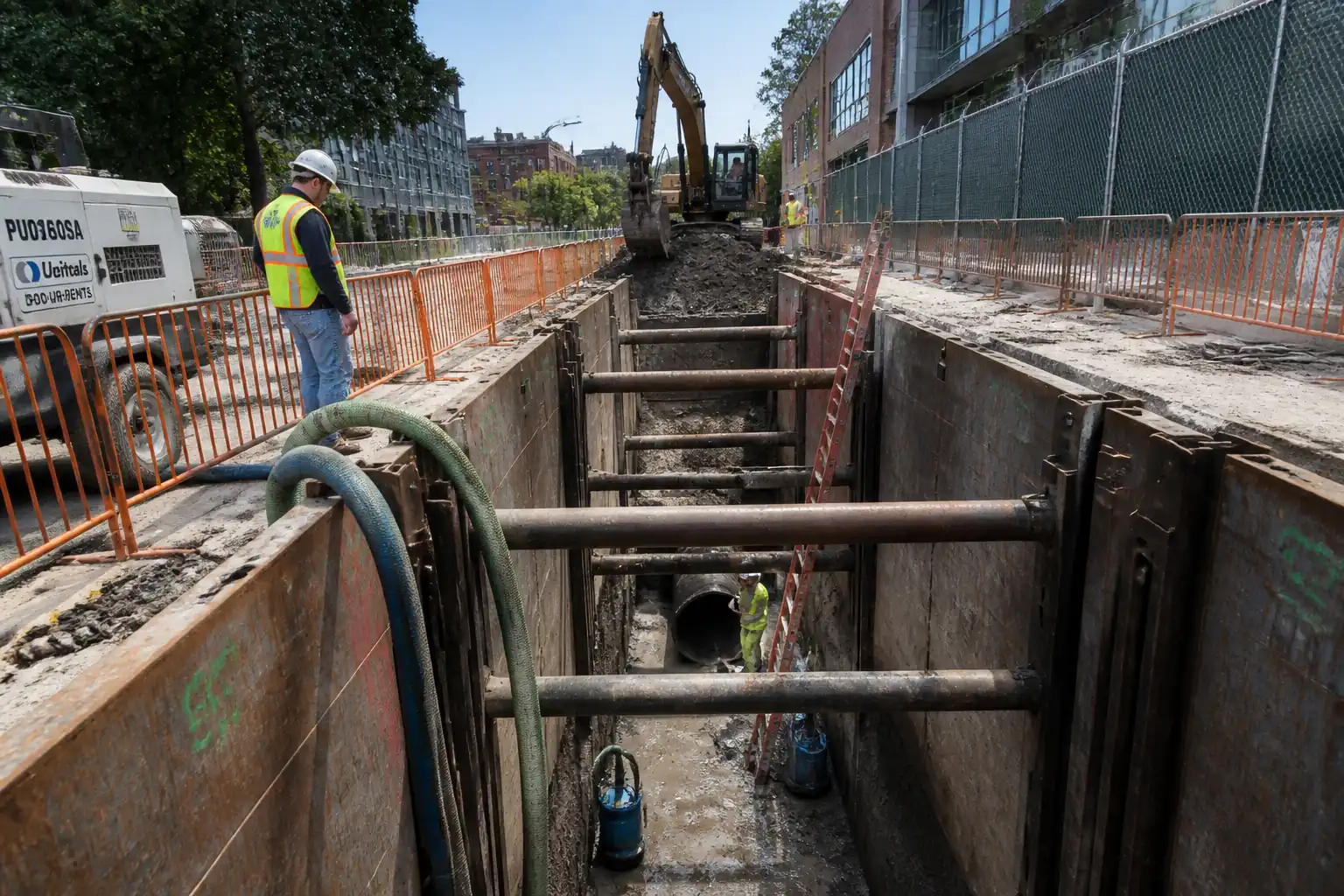
This method covers trench excavation and support, bedding, laser-guided installation of precast concrete stormwater pipes with elastomeric ring joints, granular sidefill and surround compaction, progressive backfilling, and post-installation testing (air test) between manholes, including as-built survey and reinstatement.
Inclusions
- Setting out line and level using total station and pipe laser
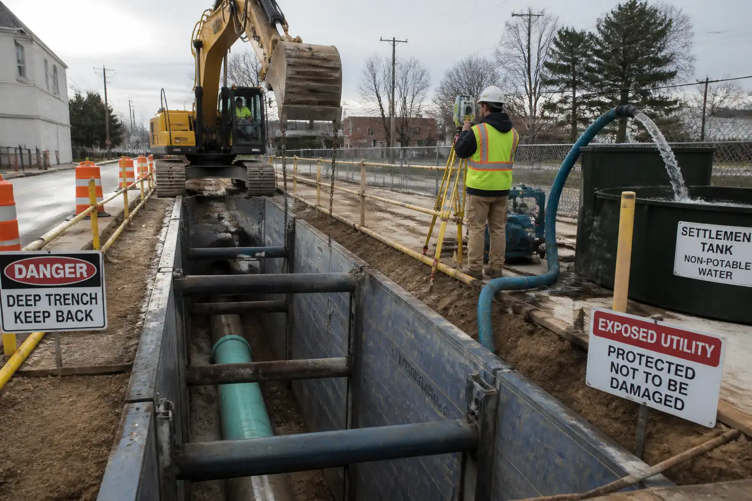
- Excavation, trench shoring/boxing, dewatering as required
- Bedding preparation (typically Class B granular) and placement
- Pipe delivery, lifting, joint preparation, ring installation, lubrication, pipe pulling, and alignment checks
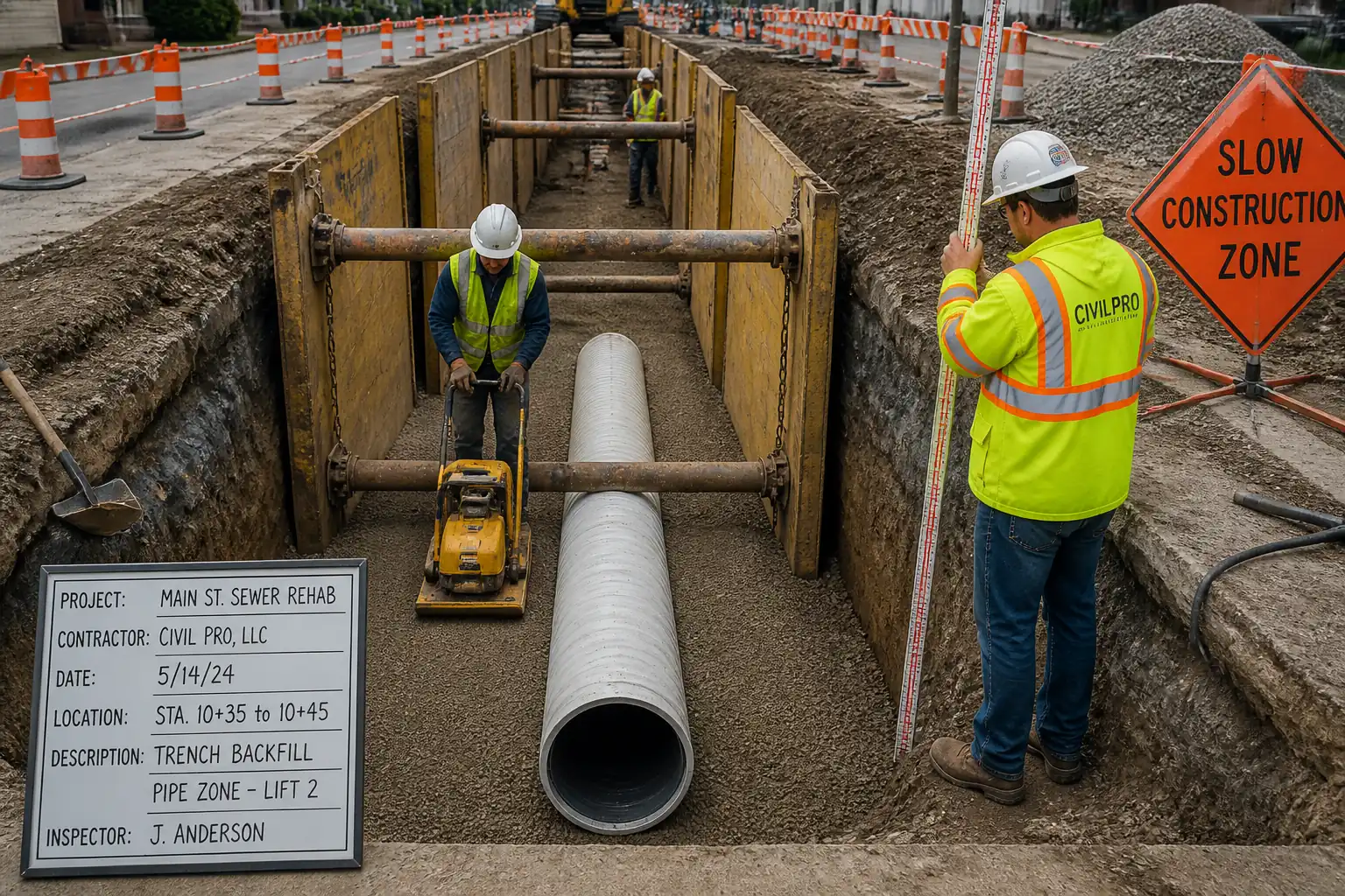
- Granular sidefill and surround compaction to 150 mm above crown
- Progressive backfilling and surface reinstatement (where specified)
- Sectional low-pressure air testing per EN 1610 (or ASTM alternative) and defect rectification
- Protection of installed works, housekeeping, and demobilization
Exclusions
- Construction of manholes/chambers (unless explicitly called off in drawings)
- Diversions/temporary over-pumping
- Permanent connections to existing live networks (covered under separate method)
Typical Ranges and Tolerances [Verify per project specifications]
- Trench width: OD + 300 to 600 mm depending on depth and compaction needs
- Bedding thickness below pipe: ≥100 mm (granular, Class B)
- Surround above crown: ≥150 mm
- Line/level tolerance at joint: ±10 mm line, ±6 mm level over 10 m
- Compaction: 95% MDD (bedding/backfill) unless otherwise specified
- Joint angular deflection: per manufacturer (typ. 0.5°–2.0°)
- Air test: Low-pressure air test per EN 1610 (test pressure and duration per DN as specified in code)
References
| Document Type | Reference / Number | Revision | Notes |
|---|---|---|---|
| Standard | BS EN 1610 | Primary reference for trenching, bedding, backfilling, and testing. | |
| Standard | BS EN 1916 / BS 5911 | Pipe dimensions, strength classes, and tolerances. | |
| Standard | BS EN 681-1 | Material and performance of rubber rings. | |
| Standard | BS EN 13242 | Granular bedding and surround material requirements. | |
| Code of Practice | BS 5975 | Temporary Works Coordinator (TWC) and design/inspection regime. | |
| Standard | EN 13331 (Parts 1–2) | Specifications for proprietary trench boxes/shoring. | |
| Standard | BS EN 13155 | Use of approved lifting clutches/clamps for pipes. | |
| Standard | ASTM C969 | Use only where specified as alternative to EN 1610. | |
| Guidance | ISO 17123 series (where applicable) | Instrument verification and field checks. |
Responsibilities
| Role | Responsibility | Name / Party |
|---|---|---|
| PM | Ensure permits, approvals, and resources are available. | Contractor |
| TWC | Approve and brief temporary works; ensure inspections logged. | Contractor |
| Engineer | Maintain line/level control; instrument calibration records. | Contractor |
| Foreman | Supervise crew, housekeeping, coordination with plant. | Contractor |
| HSE | Ensure controls implemented; stop-work if unsafe. | Contractor |
| QA/QC | Coordinate QA inspections, test frequencies, NCRs. | Contractor |
| AP/Lift Sup. | Lift plan, selection of accessories, exclusion zones. | Contractor |
| Engineer | Accept key stages as per ITP. | Employer/Engineer |
Resources
| Resource Type | Description | Quantity | Remarks |
|---|---|---|---|
| Manpower | 3–6 operatives incl. pipelayer, topman, banksman. | As required | |
| Manpower | Operate excavator for trenching and handling. | 1–2 | |
| Manpower | Setting out, laser control, as-built survey. | 1 | |
| Manpower | Safety oversight and permits. | 1 |
Materials
| Material | Specification / Grade | Quantity | Remarks |
|---|---|---|---|
| Concrete pipe | Strength class, joint profile per design [Verify]. | As per BOQ | |
| Rubber ring | Per pipe manufacturer. | 1 per joint + spares | |
| Granular aggregate | Class B bedding unless noted [Verify]. | As designed | |
| Lubricant | As required | ||
| Marker tape | As required |
Equipment
| Equipment | Capacity / Type | Quantity | Inspection Required |
|---|---|---|---|
| Excavator | 1–2 | Yes | |
| Shoring | As required | Yes | |
| Lifting accessories | Adequate for heaviest pipe + factor | Set | Yes |
| Pipe laser | 1 | Yes | |
| Survey instruments | 1 | Yes | |
| Compactors | As required | Yes | |
| Air test kit | 1 set | Yes | |
| Pumps | As required | Yes |
Prerequisites
- Approvals: Approved Issued-for-Construction drawings, Method Statement, ITP, Temporary Works design/check certificates, permits-to-excavate, traffic management approval, dewatering/ discharge permit [Verify per project].
- Utilities: Desktop study and site utility survey (GPR/EML), potholing to confirm positions/depths, no-dig zones marked; utility owner notifications logged.
- Temporary Works: TWC appointed; design brief and design for trench support accepted; inspection regime defined; permit-to-load for shoring before entry.
- Calibrations: Current calibration for lasers, gauges, total station; daily field checks documented.
- Materials: CoC/CoA for pipes, gaskets, aggregates; storage area level with timber/tyre dunnage; protect gaskets from UV/contamination.
- HSE: Task-specific risk assessment/Method Statement briefing; lift plan approved; exclusion zones planned; emergency/ rescue plan for trench incidents; first aid provisions; environmental controls in place.
- Survey Control: Primary/secondary control points established; benchmark transfer checks within tolerance; offsets/ profiles prepared.
- Weather/Water: Groundwater level assessed; plan for dewatering; avoid installation during inundation or freezing conditions unless controlled.
- Air Test Plan: Test sections defined (typically manhole-to-manhole); acceptance standards identified (EN 1610 or ASTM C969); hold/witness points scheduled with Engineer.
Method Sequence
| Step | Activity | Description | Responsibility | Inspection / Hold Point |
|---|---|---|---|---|
| 1 | Site establishment and briefing | Mobilize plant; establish access/egress; set out exclusion zones; conduct toolbox talk and lift plan briefing. | Foreman / HSE / AP | Prestart HSE inspection |
| 2 | Setting out and laser control | Install control points; set line/level; position pipe laser at upstream manhole; verify grade with two-peg test; record initial line/grade. | Site Engineer | Survey spot-checks |
| 3 | Excavation to formation with shoring | Excavate trench in runs; install shoring progressively before personnel entry; maintain trench width OD + 300–600 mm [Verify]; step/bench or shore as per TWD; manage groundwater with pumps. | Foreman / TWC oversight | TWC/competent person trench inspection |
| 4 | Formation trimming and proofing | Trim base to level; remove soft spots; replace with compacted granular; check invert level/grade vs design. | Foreman / Site Engineer | Engineer check |
| 5 | Bedding placement (Class B granular) | Place ≥100 mm granular bedding; level and lightly compact; form cradle per DN; no oversize particles or protrusions. | Foreman / QA/QC | Visual and level checks |
| 6 | Pipe delivery inspection and preparation | Inspect pipe barrels/bells and spigots; clean sockets/spigots; check witness marks; fit correct ring to groove per manufacturer; verify socket orientation plan (upstream). | QA/QC / Foreman | Visual inspection at trench edge |
| 7 | Pipe lifting and lowering | Attach certified lifting clutches/chains; lift per plan; maintain control with tag lines; lower onto bedding with blocks/cribs to avoid ring displacement. | Lift Supervisor / Operator | Lift supervision |
| 8 | Joint lubrication and assembly | Lubricate spigot and ring with approved lubricant; align spigot to socket; pull joint together using pipe puller/come-along or gentle push with excavator against timber buffer; do not damage bell. | Foreman / Pipelayer | Joint inspection |
| 9 | Alignment and level verification | Check line with pipe laser target; confirm invert levels at each joint; adjust bedding by lifting and packing—not by point loading pipe. | Site Engineer | Survey check |
| 10 | Sidefill placement and compaction | Place granular sidefill evenly both sides in 150 mm layers to springline; rod/tamp to eliminate voids; avoid pipe displacement; continue to 150 mm above crown (surround). | Foreman / QA/QC | Layer inspection |
| 11 | Progressive laying | Repeat Steps 6–10 for subsequent pipes; maintain socket upstream; limit joint deflection per manufacturer; cap open ends at close of shift. | Foreman | Ongoing |
| 12 | Initial backfill above surround | Backfill in layers above surround to subgrade; increase compaction energy only after minimum 300 mm cover above crown [Verify]; keep heavy plant off trench until cover achieved. | Foreman / QA/QC | Layer checks |
| 13 | Air testing of installed section | On reaching next manhole, install stoppers; conduct low-pressure air test per EN 1610 (test method and pressure/time per DN); alternative ASTM C969 if specified. If failure, locate leak (soap solution), rectify, retest. | QA/QC / Site Engineer | Witness by Engineer (Hold) |
| 14 | As-built survey | Survey inverts, centerline, and cover levels; record joint deflections if applicable; update redlines/CAD. | Surveyor | Document review |
| 15 | Reinstatement and demobilization | Complete backfill/reinstatement per authority; remove shoring progressively; clear site; hand over records. | Foreman / PM | Final inspection |
Health, Safety and Environmental Controls - Safety
Key Hazards, Consequences, and Controls
1) Hazard: Trench collapse
- Consequence: Crush/asphyxiation, fatality
- Engineering/Procedural Control: Temporary works design and shoring per BS 5975/EN 13331; no entry into unsupported trenches; daily inspections by competent person and after rainfall; maintain spoil setback ≥0.6–1.0 m from edge [Verify].
- Required PPE: Helmet with chinstrap, safety boots, gloves, eye protection
- Collective Measure: Trench boxes/shoring, edge barriers
- Inspection/Permit/Supervision: Permit-to-excavate; TWC approval; daily trench inspection log; stop-work if non-compliant
2) Hazard: Underground utility strike
- Consequence: Electrocution, explosion, flooding, service outage
- Engineering/Procedural Control: GPR/EML survey, potholing, utility maps; set no-dig exclusion zones; hand-dig near known services; liaison with utility owners
- PPE: Dielectric gloves (where appropriate), eye protection
- Collective Measure: Spotter/banksman, insulated tools for hand-dig
- Inspection/Permit/Supervision: Permit with utility plans; supervisor authorization before machine excavation near services
3) Hazard: Lifting and lowering of pipes
- Consequence: Crush injuries, dropped loads
- Engineering/Procedural Control: Appointed Person lift plan; certified lifting points/clutches; tag lines; dedicated banksman; exclusion zone under load
- PPE: Helmet, gloves, safety boots, hi-vis
- Collective Measure: Barriers and radios; lift supervisor present
- Inspection/Permit/Supervision: Lifting gear certificates; pre-use checks; recorded toolbox talk
4) Hazard: Pipe jointing forces and pinch points
- Consequence: Hand injuries, sudden pipe movement
- Engineering/Procedural Control: Use pipe puller/come-along; do not place hands between spigot and socket; use timber buffer if pushing with excavator; slow controlled pulls
- PPE: Cut-resistant gloves, eye protection
- Collective Measure: Exclusion zone around jointing area
- Inspection/Permit/Supervision: Foreman to supervise; method briefing recorded
5) Hazard: Working at edge of trench / falls
- Consequence: Falls causing serious injury
- Engineering/Procedural Control: Edge protection where practicable; designated access/egress ladders; maintain good housekeeping and lighting
- PPE: Helmet, boots
- Collective Measure: Physical barriers and signage
- Inspection/Permit/Supervision: Daily HSE walkdown; lighting checks for dusk/night work
6) Hazard: Air testing – pressurized system
- Consequence: Stopper ejection, impact injuries
- Engineering/Procedural Control: Rated stoppers with safety lanyards; relief valves; exclusion zone; pressurize gradually; never stand in line with plugs
- PPE: Helmet, eye protection, gloves
- Collective Measure: Barriers; test signage
- Inspection/Permit/Supervision: Gauge calibration; Engineer witness per ITP; test permit [Verify per HSE plan]
7) Hazard: Plant–pedestrian interface
- Consequence: Struck-by injuries
- Engineering/Procedural Control: Segregated walkways; banksman for reversing; 360° cameras/alarms; no-go zones within slew radius
- PPE: Hi-vis, boots, helmet
- Collective Measure: Barriers, signage, spotters
- Inspection/Permit/Supervision: Traffic Management Plan; supervisor enforcement
8) Hazard: Confined space (large-diameter pipes/manholes)
- Consequence: Asphyxiation, toxic exposure, entrapment
- Engineering/Procedural Control: Confined space risk assessment; gas testing; ventilation; rescue plan; permit-to-work
- PPE: Gas monitor, harness where required, helmet
- Collective Measure: Tripod/winch (if vertical access), standby attendant
- Inspection/Permit/Supervision: Confined space permit; trained entrants/attendants [Verify per local regulations]
9) Hazard: Laser equipment
- Consequence: Eye injury
- Engineering/Procedural Control: Class 2/3R lasers only; do not view beam directly; place below eye level; signage
- PPE: Eye protection as needed
- Collective Measure: Controlled access
- Inspection/Permit/Supervision: Equipment calibration and operator training records
10) Hazard: Manual handling of rings/accessories
- Consequence: Strains/sprains
- Engineering/Procedural Control: Use mechanical aids; team lift; rotate tasks
- PPE: Gloves, back support if prescribed
- Collective Measure: Staging platforms; minimize carry distances
- Inspection/Permit/Supervision: Manual handling training; supervision checks
[Verify per project HSE plan and local regulations].
Health, Safety and Environmental Controls - Environmental
Environmental Risks and Controls
- Dewatering and water quality
- Risk: Turbid discharge to watercourses/drains
- Control: Use settlement tanks/bags, silt fences; discharge only under permit; monitor turbidity where required
-
Inspection: Daily checks; log pump operation and discharge points
-
Spoil and material management
- Risk: Contamination, excess waste to landfill
- Control: Segregate clean spoil vs contaminated; reuse compliant materials; dispose via licensed carriers; records retained
-
Inspection: Waste transfer notes; stockpile stability/cover checks
-
Dust and mud on roads
- Risk: Nuisance, safety hazards
- Control: Water suppression; wheel wash/road sweeper; cover loads; limit vehicle speeds
-
Inspection: Daily log; photographs if complaints
-
Noise and vibration
- Risk: Disturbance to receptors
- Control: Working hours compliance; acoustic shrouds where practicable; maintain equipment; positioning of pumps away from receptors
-
Inspection: Noise spot checks if required; complaint register
-
Fuel, oils, lubricants
- Risk: Spills to ground/water
- Control: Double-bunded storage; spill kits; refuel in designated areas; train operators
-
Inspection: Weekly spill kit and bund checks; incident log
-
Ecology and groundwater
- Risk: Habitat disturbance; drawdown effects
- Control: Check ecological constraints; minimize footprint; manage dewatering rates; reinstate promptly
-
Inspection: Environmental inspections and, if required, monitoring
-
Materials compliance
- Risk: Non-conforming aggregates or gaskets leading to remedial works
- Control: Pre-approval of suppliers; certificates of compliance; random testing per ITP
- Inspection: QA/QC review and testing
[Verify per project EMP and permits].
Quality Assurance and Quality Control
Controls and Records
-
Hold/Witness Points:
1) Trench support in place before entry (Witness)
2) Bedding prepared and approved (Hold)
3) First joint assembly and alignment (Witness)
4) Surround to springline and 150 mm above crown (Witness)
5) Air testing of each section (Hold)
6) Backfill above pipe to subgrade (Witness) -
Tolerances [Verify per specifications]:
- Line: ±10 mm at any joint relative to design line
- Level: ±6 mm over 10 m run; invert levels per drawings
- Bedding thickness: ≥100 mm; surround ≥150 mm above crown
- Trench width: OD + 300–600 mm
- Compaction: ≥95% MDD unless otherwise specified
-
Joint deflection: per manufacturer limits (typ. 0.5°–2.0°)
-
Testing and Frequency:
- Aggregates: Sieve analysis at source or per lot [e.g., 1 per 200 t] [Verify]
- Compaction: Field density tests [e.g., 1 per 50 m per layer zone] where practicable [Verify]
- Air test: Each section between manholes; retest after repairs
-
Instrument checks: Daily two-peg test/laser verification
-
Records:
-
ITP checklists, delivery tickets, CoC/CoA, calibration certificates, lift plans, trench inspections, test sheets, as-built survey, NCR/CAR where applicable
-
Nonconformance:
-
Record NCR; agree corrective action with Engineer; re-inspect/retest; update as-built if geometry changes
-
Protection:
-
Cap open pipe ends nightly; prevent debris ingress; restrict heavy plant over trench until minimum cover achieved
-
Training/Competence:
-
Operators certified; banksman trained; confined space certification as required; competent persons for trench inspection
-
Coordination:
- Interface with existing utilities and other trades; maintain clear communication and daily coordination meetings as needed.
Attachments
- Approved Temporary Works Design and TWC Inspection Forms
- Lift Plan and Lifting Accessories Certificates
- Calibration Certificates (pipe laser, rotating laser/TS, pressure gauges)
- Material Certificates (Pipes: BS EN 1916/BS 5911; Rings: BS EN 681-1; Aggregates: BS EN 13242)
- ITP Checklists and Test Records (compaction, air tests)
- Daily Trench Inspection Logs and Permits-to-Excavate
- Traffic Management Plan (if applicable)
- Dewatering Plan/Permits and Water Quality Logs
- As-Built Survey and Redlined Drawings
- Toolbox Talk Attendance and Training Records
This content is a read-only public reference. Download or customize to get an editable version.
ITP preview
The first inspection activities from the linked ITP for Method Statement: Excavation, Bedding, and Installation of Precast Concrete Stormwater Pipes with Shoring, Laser Alignment, Rubber Ring Joints, Surround Compaction, and Air Testing:
| Activity | Inspection / Test | Acceptance Criteria | Responsibility | Record |
|---|---|---|---|---|
| Material receipt – pipes and gaskets | Check CoC/CoA; visual for defects; confirm joint type/ring size | Conform to BS EN 1916/BS 5911 and BS EN 681-1; no damage to sealing faces | QA/QC Engineer / Foreman | Material inspection form; delivery notes |
| Trench excavation and support | Check width, depth, support per TWD; spoil setback; access/egress | Stable, shored trench per TWD; dimensions within tolerance; safe access | TWC / Foreman / HSE | Trench inspection log; permit-to-excavate |
| Bedding preparation (Class B) | Thickness and profile; material compliance | ≥100 mm thickness; level ±10 mm; aggregate per BS EN 13242 | QA/QC / Site Engineer | Bedding inspection sheet; test reports |
Showing 3 of 8 inspection activities. View full ITP →
Related Inspection and Test Plan
An Inspection and Test Plan (ITP) is available for Method Statement: Excavation, Bedding, and Installation of Precast Concrete Stormwater Pipes with Shoring, Laser Alignment, Rubber Ring Joints, Surround Compaction, and Air Testing. The ITP defines the inspection activities, acceptance criteria, hold and witness points, responsible parties, and records required to verify the work described in this method statement.
View the Method Statement: Excavation, Bedding, and Installation of Precast Concrete Stormwater Pipes with Shoring, Laser Alignment, Rubber Ring Joints, Surround Compaction, and Air Testing ITP →Frequently asked questions
Continue with related Quollnet resources connected to this method statement.