Method Statement – Installation of Metal Parapet Coping Caps and Flashings – Method Statement
AI-assisted method statement with matching ITP, PDF download, and Excel export.
More than a static template
Unlike a downloadable Word or PDF template, this method statement is an AI-assisted editable starting point connected directly to a matching Inspection and Test Plan. Every section is structured, project-adaptable, and ready to export.
- AI-assisted drafting — Customize every section with AI for your specific project scope.
- Linked ITP — A matching inspection and test plan is generated alongside the method statement.
- Multiple export formats — Download as a formatted PDF or editable Excel spreadsheet.
- Editable starting point, not a final document — Review, verify, and adjust all content against your project requirements before use.
Static template vs. Quollnet workflow
| Feature | Static template | Quollnet |
|---|---|---|
| Project-specific content | Manual fill-in required | AI-assisted customization |
| Linked ITP | Separate document, no link | Matching ITP included |
| Export formats | Usually PDF only | PDF and Excel |
| Structured sections | Free-form layout | 13 standardized sections |
| Saved to your account | Local file only | Cloud-saved, reusable |
| Content accuracy | You verify everything | AI-assisted, you still verify |
| Cost | Often free but time-intensive | Free to customize and download |
What you can customize
When you save this method statement to your account, every section becomes editable. The following 13 sections are included:
- Scope — Defines the activity and its boundaries.
- References — Standards, specifications, and drawings.
- Responsibilities — Roles and accountabilities.
- Resources — Labour, plant, and equipment summary.
- Materials — Materials and compliance requirements.
- Equipment — Tools and equipment details.
- Prerequisites — Hold points and pre-conditions.
- Method sequence — Step-by-step construction sequence.
- Safety controls — HSE risk controls and PPE.
- Environmental controls — Environmental mitigation measures.
- QA/QC — Quality inspection and test requirements.
- ITP — Inspection and Test Plan table (has its own page).
- Attachments — Referenced drawings and documentation.
Why this method statement is used
This method statement is used to define and communicate the approved procedure for carrying out method statement – installation of metal parapet coping caps and flashings on site. It ensures the work is planned in advance, the correct resources and controls are in place, and all personnel understand responsibilities, sequence, quality requirements, and safety controls before work begins. It aligns site execution with the documented scope and acceptance expectations.
Who uses this method statement
This method statement is used by contractors, site supervisors, project engineers, QA/QC engineers, HSE officers, consultants, and client representatives. It serves as a shared reference for planning, execution, supervision, inspection, and approval of the activity on site.
When it is prepared and submitted
The method statement is prepared before the work activity starts and submitted as part of the pre-construction documentation package for review and approval.
Who reviews or approves it
The method statement is usually submitted to the client representative, consultant, resident engineer, or project management consultant for review and approval before the work commences.
Important approval note
This method statement is an AI-assisted editable starting point, not a pre-approved document. Before use on any project, all content must be reviewed and approved by the relevant parties (superintendent, principal contractor, or client representative) in accordance with your contract and project quality plan.
For example: if your specification requires a departure from a referenced standard, that departure must be documented and approved separately — this method statement will not capture that automatically. Always verify against your applicable drawings, specifications, and regulatory requirements.
Method statement content
Scope
Scope of Work
- Supply, fabrication, and installation of metal parapet coping caps and associated flashings to parapet walls, including internal/external corners, end caps, transitions, and terminations.
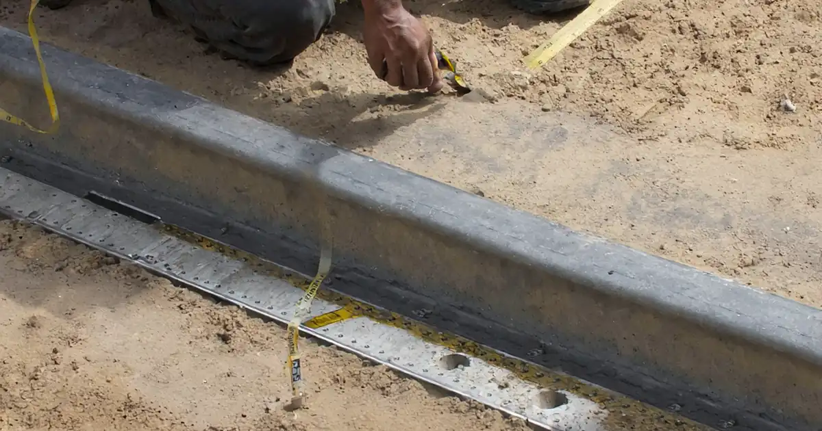
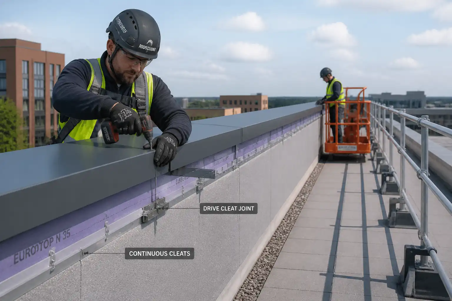
- Continuous cleat mechanical installation to parapet faces, avoiding through-fasteners on coping horizontal surfaces.
- Jointing of coping sections using concealed internal splice plates and drive cleats to allow thermal movement.
- Installation of waterproofing underlayment backing to parapet tops and downstands, including tie-in with roof membrane and counter-flashings.
- Accommodation of thermal expansion/contraction, including provision of expansion gaps at joints and detailing to prevent oil-canning and distress.
- Integration and coordination with roofing works at parapet upstands, terminations, and reglets.
- Quality control, inspections, testing, protection, and handover documentation.
Exclusions / Interfaces
- Primary roof membrane installation and warranty (by Roofing Trade).
- Structural parapet construction/modifications (by Civil/Structural Trade).
- Lightning protection, fall-arrest anchors, and parapet cappings for balustrades (by others unless noted).
- Any hot works requiring permits unless specifically approved.
Key Performance Requirements
- Weatherproof, durable, corrosion-resistant coping system with neat, consistent appearance.
- No visible fasteners on horizontal top surface; uniform alignment and consistent reveals.
- Movement-capable joints with sealed weather laps and continuous support.
- Compatibility with roof membrane and adjacent materials.
- Tolerances and acceptance criteria as stated herein. [Verify per project specifications].
References
| Document Type | Reference / Number | Revision | Notes |
|---|---|---|---|
| Standard | SMACNA | Profiles, cleats, joints, hem details, and tolerances. | |
| Guideline | NRCA | Parapet terminations and waterproofing interfaces. | |
| Standard | ASTM A653 | Coating class G90/Z275 typical for exterior. [Verify] | |
| Standard | ASTM B209 | Alloy/temper per manufacturer. Typical 3003-H14/5005-H34. [Verify] | |
| Standard | ASTM A240 | Type 304/316 finish No. 2B or brushed. [Verify] | |
| Standard | ASTM D1970 | Use for parapet tops and downstands; temperature limits apply. | |
| Standard | ASTM C920 | Type S or M, Grade NS, Class 25 or higher; exterior UV-resistant. | |
| Standard | ASTM C1311 | Use continuous beads at laps and splice plates. | |
| Standard | ASTM D226 | As separation/slip sheet where specified. | |
| Standard | AAMA 2605/2604 | 70% PVDF for severe exposure; verify color/thickness. | |
| Standard | ISO 12944 | Use for environmental category selection. [Verify project exposure class] | |
| Standard | BS EN 508-1/-2 | Applicable where EU/UK standards govern. [Verify] | |
| Code/Standard | IBC / ANSI/SPRI ES-1 | Edge securement design and testing requirements. [Verify] |
Responsibilities
| Role | Responsibility | Name / Party |
|---|---|---|
| Project Manager | Project Manager – Overall delivery, resources, program, commercial control. | Contractor |
| Site/Project Engineer | Site/Project Engineer – Method compliance, setting out, interface coordination, ITP implementation, as-builts. | Contractor |
| Supervisor/Foreman | Construction Supervisor/Foreman – Daily task briefings, workmanship, sequencing, productivity. | Contractor |
| QA/QC Engineer | QA/QC Engineer – Inspections, records, NCRs, coordination of tests, witness/hold points, final dossiers. | Contractor |
| HSE Officer | HSE Officer – Task-specific risk assessment, permits (work at height), inspections, monitoring, toolbox talks. | Contractor |
| Surveyor | Surveyor – Control points, level/alignment checks of parapet, as-built survey. | Contractor |
| Consultant/Client | Consultant/Client Representative – Review/approve submittals, mock-up, and hold-point inspections. | Client/Consultant |
| Manufacturer/Supplier | Provide data sheets, shop drawings, installation recommendations, warranty terms, and technical support. | Vendor |
Resources
| Resource Type | Description | Quantity | Remarks |
|---|---|---|---|
| Site Supervision | 1 | ||
| Engineering/QA | 2 | ||
| HSE | 1 | ||
| Skilled Labor | 4–6 | ||
| Plant Operators | 1–2 |
Materials
| Material | Specification / Grade | Quantity | Remarks |
|---|---|---|---|
| Metal Coping Caps | Per AAMA 2605/ASTM as noted | As per BOQ | Finish/color per schedule |
| Cleats (continuous) | Per SMACNA details | As required | Corrosion class per exposure [Verify] |
| Splice Plates | Per manufacturer | 1 per joint | |
| Drive Cleats | Per SMACNA/manufacturer | 1 per joint | |
| Waterproofing Underlayment | ASTM D1970 | As required | Tie into roof membrane |
| Sealants and Butyl Tapes | ASTM C920/C1311 | As required | Color to match coping where exposed |
| Fasteners/Anchors | ASTM F593 (where applicable) | As required | No carbon steel in wet zones |
| Isolation/Slip Sheets | Per manufacturer | As required |
Equipment
| Equipment | Capacity / Type | Quantity | Inspection Required |
|---|---|---|---|
| Access Equipment | Per tag | As required | Yes |
| Hand/Power Tools | Sets as required | Yes | |
| Survey Tools | 1 set | Yes | |
| Lifting Aids | Rated/Certified | As required | Yes |
| Safety Equipment | 1 each | Yes |
Prerequisites
Approvals and Submittals
- Approved shop drawings showing profiles, cleats, splice details, corners, and terminations; include thermal movement calculations and joint gaps.
- Material submittals with certificates of conformity (ASTM/AAMA compliance), color samples, sealant compatibility statements, and MSDS/SDS.
- Mock-up: Minimum 1.5 m long straight run with one joint and one external corner; obtain Consultant approval as quality benchmark.
Site Readiness
- Parapet constructed, cured (concrete ≥ 7 days minimum, [Verify]), and within tolerance: top level variation ≤ ±5 mm in 3 m; face plumb within ±5 mm in 3 m; top slope to roof side 1:6 to 1:12 preferred [Verify].
- Blocking/backing installed and fixed; timber moisture content ≤ 19% [Verify].
- Roof membrane upstand installed by roofer or prepared for tie-in; compatibility confirmed.
Permits and Controls
- Permit to Work at Height with rescue plan approved.
- Hot Work Permit if soldering/welding any end dams (if applicable).
- Lifting plan for handling long sections if using crane/MEWP.
Weather and Environmental Constraints
- Install self-adhered underlayment at substrate temperatures per manufacturer, typically ≥ 5°C and dry surfaces.
- Do not install coping in high winds > 10 m/s due to handling risk and alignment issues. [Verify].
Calibration and Tools
- Torque drivers calibrated within last 6 months.
- MEWP/scaffold inspected and tagged within last 7 days (per site rules).
Coordination
- Interface meeting with Roofing Trade to agree tie-in sequencing and temporary weathering.
- Confirm dissimilar metal interfaces and required isolation.
Materials Handling
- Inspect delivered coping sections for damage; store on dunnage, protected from distortion and scratching; do not stack more than manufacturer’s recommended height.
Method Sequence
| Step | Activity | Description | Responsibility | Inspection / Hold Point |
|---|---|---|---|---|
| 1 | Set-out and Verification | Verify parapet dimensions, straightness, and slope. Mark coping centerline and cleat lines. Confirm coping width covers parapet plus required drips; typical overhang 25–40 mm each side [Verify]. | Site Engineer / Surveyor | Dimensional survey |
| 2 | Substrate Preparation | Clean parapet top and faces; repair voids; ensure dry. Install isolation layer over masonry where specified to avoid galvanic action with metal. | Foreman | Visual |
| 3 | Underlayment Installation | Apply self-adhered underlayment over parapet top and down both faces ≥150 mm; roll firmly to bond; lap per manufacturer (typically 75–100 mm). Tie into roof membrane or leave shingle-lap for later tie-in. | Roofer/Sheet Metal Installer | Adhesion check; lap inspection |
| 4 | Fabrication Check | Confirm coping, cleats, splice plates, and corners match approved shop drawings. Dry-fit one bay if necessary. | QA/QC | Visual, measurement |
| 5 | Install Continuous Cleats | Fix continuous cleats to both parapet faces per profile. Fastener spacing: 200–300 mm o/c [Verify]; 50–75 mm from ends. Embedment: wood ≥30 mm; steel full thread; concrete/masonry per anchor approval. Stagger fasteners vertically. Maintain straightness ±3 mm per 3 m. Do not distort cleats. | Installers | Fastener spacing/edge distance check; torque spot checks |
| 6 | Corners and Terminations | Install pre-formed internal/external corners and end caps. Provide end dams ≥25 mm at terminations. Seal concealed laps with butyl tape; solder/weld only where specified and permitted. | Installers | Fit-up and sealing check |
| 7 | Internal Splice Plates at Joints | Place splice plate centered under each joint with butyl tape both sides of joint. Fix splice plate to one coping section only; maintain designed slip on adjacent section. Do not fasten through coping top. | Installers | Joint preparation check |
| 8 | Coping Section Placement | Place coping over cleats; engage hems uniformly along length. Ensure even overhang/reveal both sides. Protect finishes during handling. | Installers | Alignment check |
| 9 | Thermal Expansion Gaps | Set expansion gap between coping sections based on α·L·ΔT. Typical joint gap 6–12 mm for 3–4 m long aluminum sections; 4–8 mm for steel/stainless [Verify]. Do not seal the gap rigidly; allow concealed movement over splice. | Site Engineer/Installers | Measure gap at each joint |
| 10 | Drive Cleat Jointing | Fit drive cleat across joint to lock both coping hems without penetrating top. Tap in progressively to achieve snug fit; avoid paint damage. Apply discrete sealant only where specified and not restricting movement. | Installers | Engagement check |
| 11 | Counter-Flashings/Tie-ins | Install counter-flashings/reglets to tie coping to roof membrane upstand per roofing detail. Sealant per ASTM C920 where exposed. | Installers/Roofer | Compatibility and lap check |
| 12 | Final Fix, Protection, and Cleaning | Remove protective films; clean surfaces with approved cleaner; remove swarf. Install temporary protection if other trades ongoing. Record as-builts. | Installers/QA | Final visual inspection |
Health, Safety, and Environment – Safety Controls
Task-Specific Hazards and Controls
1) Hazard: Working at height at roof edge
- Likely consequence: Fall from height causing serious injury or fatality.
- Engineering/procedural control: Install edge protection/guardrails or use MEWP with inward-facing work; where not feasible, use certified fall arrest with lifelines/anchorage; maintain 2 m exclusion from unprotected edges with warning lines. Develop rescue plan.
- Required PPE: Full body harness with double lanyard SRL where applicable, helmet with chinstrap, non-slip safety footwear.
- Collective preventive measure: Guardrails and toeboards prioritized over personal fall arrest.
- Inspection/permit/supervision: Work at Height Permit; daily inspection of harness and MEWP; supervisor to monitor wind limits. [Verify per project HSE plan and local regulations].
2) Hazard: Manual handling of long, sharp-edged coping sections in windy conditions
- Likely consequence: Musculoskeletal strain, lacerations, dropped objects.
- Engineering/procedural control: Team lifts with coordinated commands; use panel carriers/suction cups; avoid handling above 10 m/s wind; store flat on dunnage; use tag lines when lifting.
- PPE: Cut-resistant gloves (ANSI/EN level appropriate), long sleeves, safety glasses.
- Collective measures: Mechanical aids and team lifts; exclusion zone below workface.
- Inspection/permit/supervision: Lifting plan and toolbox talk; supervisor to enforce wind/weather stop criteria.
3) Hazard: Drilling/anchoring into masonry/steel/wood
- Likely consequence: Silica dust inhalation, eye injury, hand injury, noise exposure.
- Engineering/procedural control: Use vacuum dust extraction or wet suppression on masonry; clamp or secure workpieces; use torque-limited drivers; maintain guards.
- PPE: Safety glasses/face shield, hearing protection, dust mask/respirator (P2/P3 as required), gloves.
- Collective measures: Local exhaust ventilation; noise barriers/time restrictions.
- Inspection/permit/supervision: PAT/inspection of tools; check drill bits; noise monitoring if required.
4) Hazard: Contact with roof membrane and potential puncture
- Likely consequence: Water ingress and property damage.
- Engineering/procedural control: Lay protection boards/mats on membrane; prohibit sharp offcuts on roof; immediate cleanup of swarf.
- PPE: Soft-soled footwear; gloves.
- Collective measures: Designated material staging zones away from membrane edges.
- Inspection/permit/supervision: Supervisor to inspect protection before and after shift.
5) Hazard: Chemical exposure from sealants/primers
- Likely consequence: Skin/respiratory irritation, sensitization.
- Engineering/procedural control: Use low-VOC, manufacturer-approved products; ensure ventilation; follow SDS; avoid skin contact.
- PPE: Nitrile gloves, safety glasses; respirator if required by SDS.
- Collective measures: Store chemicals in bunded trays; spill kit nearby.
- Inspection/permit/supervision: SDS available; HSE officer to verify product approvals.
6) Hazard: Sharp edges and burrs on sheet metal
- Likely consequence: Lacerations.
- Engineering/procedural control: Deburr edges; use hand seamers, not hands, to press hems; prohibit handling without gloves.
- PPE: Cut-resistant gloves.
- Collective measures: Covered edges during transport; bins for scrap.
- Inspection/permit/supervision: Spot checks by Supervisor.
7) Hazard: Falling objects from parapet
- Likely consequence: Injury to persons below.
- Engineering/procedural control: Establish exclusion zone with toe boards/netting; tether tools; no stacking near edge; use material stops.
- PPE: Hard hats for personnel below.
- Collective measures: Physical barriers and tool lanyards.
- Inspection/permit/supervision: Daily check of exclusion zone and tool lanyards.
8) Hazard: Hot works (only if soldering/welding end dams)
- Likely consequence: Fire, burns, fumes.
- Engineering/procedural control: Prefer cold joints; if hot works required, implement Hot Work Permit, fire watch, non-combustible shields, extinguishers.
- PPE: Heat-resistant gloves, eye/face shield.
- Collective measures: Fire watch 60 min post-work.
- Inspection/permit/supervision: Hot Work Permit; atmospheric checks if in confined areas.
9) Hazard: Adverse weather (rain, lightning)
- Likely consequence: Slips, quality defects, electrocution (lightning).
- Engineering/procedural control: Stop work during precipitation, lightning within 10 km, or on wet, slippery surfaces; secure materials.
- PPE: Weather-appropriate non-slip footwear.
- Collective measures: Weather monitoring.
- Inspection/permit/supervision: Supervisor to enforce stop-work criteria.
Environmental Controls
Environmental Management Measures
- Metal waste management: Segregate aluminum, steel, and stainless steel offcuts for recycling; maintain scrap bins with lids to prevent windblown debris.
- Sealant/primer VOCs: Select low-VOC where feasible; keep containers closed; no decanting near drains; follow SDS disposal. [Verify per project EMP].
- Dust control when drilling masonry: Use vacuum extraction; collect dust at source; avoid dry coring near air intakes.
- Noise: Schedule high-noise activities within permitted hours; use quieter tools and maintain equipment; provide hearing protection and signage.
- Spill prevention: Store chemicals on spill trays; carry spill kit; clean spills immediately; prevent entry into stormwater drains.
- Stormwater protection: Do not perform cutting/grinding that generates swarf where runoff can carry metals; use mats and temporary bunds near edges.
- Protection of roof membrane: Lay sacrificial protection sheets; no solvent spills; immediate removal of swarf to avoid rust staining.
- Wildlife and public: Maintain exclusion zones; secure materials against wind uplift; no materials left unsecured overnight on roof edges.
- Environmental incident reporting: Report and record any spills, dust exceedances, or waste mismanagement per project EMP. [Verify per project HSE plan and local regulations].
QA/QC
Quality Objectives
- Achieve a durable, watertight, and visually consistent coping and flashing installation meeting approved shop drawings and standards.
Inspections and Tests
- Material verification: Check certificates for ASTM/AAMA compliance and finish. Inspect for damage prior to installation.
- Substrate tolerance: Top level ±5 mm in 3 m; face plumb ±5 mm in 3 m; local irregularities ≤ 3 mm under 1 m straightedge [Verify].
- Cleat installation: Fastener spacing 200–300 mm o/c [Verify]; edge distance 25–40 mm; torque per fastener manufacturer; pull-out tests at start of works (minimum 2 per substrate type/elevation) with acceptance ≥ 1.0–1.5 kN [Verify].
- Jointing and expansion: Record joint gap at each splice; verify splice plate fixed one side only; confirm free sliding.
- Sealant quality: Bead size 6–10 mm where exposed; adhesion test (field peel) as required; no voids or skips.
- Alignment/appearance: Uniform reveals ±3 mm; straightness deviation ≤ 3 mm in 3 m; no oil-canning beyond manufacturer’s tolerance; color/finish match to approved sample.
- Water tightness: Visual inspection and optional directed hose test by agreement; no ingress observed at interiors/soffits.
Documentation
- Checklists: Substrate, underlayment, cleats, joints/corners, final inspection.
- Test records: Torque logs; anchor pull-out test reports.
- Material records: CoCs, SDS, batch numbers, coating warranty letters.
- As-builts: Coping layout, joint positions, expansion gaps recorded for long runs.
Nonconformance and Corrective Action
- Record NCRs for out-of-tolerance works; propose corrective actions (e.g., re-fix cleats, adjust joints, replace damaged sections) and obtain approval before rework.
Warranty and Handover
- Obtain manufacturer warranty for finish (e.g., 20 years for PVDF) and system installation warranty as specified. [Verify per project specifications].
Attachments
Attachments (to be appended)
- Approved shop drawings and manufacturer installation instructions.
- Mock-up approval photos and report.
- Material certificates (ASTM/AAMA compliance), coating warranties, and sealant compatibility letters.
- SDS for sealants, primers, and membranes.
- Torque tool calibration certificates.
- Access equipment inspection tags and MEWP certificates.
- Pull-out test method statement and results.
- ITP checklists and inspection records templates.
- As-built drawings indicating joint locations and expansion gaps.
- Risk Assessment/Method Statement (RAMS) sign-off sheets.
- Work at Height Permit and, if applicable, Hot Work Permit copies.
This content is a read-only public reference. Download or customize to get an editable version.
ITP preview
The first inspection activities from the linked ITP for Method Statement – Installation of Metal Parapet Coping Caps and Flashings:
| Activity | Inspection / Test | Acceptance Criteria | Responsibility | Record |
|---|---|---|---|---|
| Pre-Installation Review | Check approvals: shop drawings, materials, mock-up | All submittals approved; mock-up accepted; permits in place. | QA/QC Engineer / Consultant | ITP Pre-Start Checklist |
| Substrate Inspection | Levels/plumbness per tolerance | Top level ±5 mm in 3 m; face plumb ±5 mm in 3 m; sound, dry substrate. | QA/QC Engineer / Consultant | Substrate Inspection Record |
| Underlayment Installation | Adhesion (hand peel), lap width | Full bond; laps sealed; laps ≥ 75–100 mm [Verify]. | QA/QC Engineer | Underlayment Inspection Sheet |
Showing 3 of 8 inspection activities. View full ITP →
Related Inspection and Test Plan
An Inspection and Test Plan (ITP) is available for Method Statement – Installation of Metal Parapet Coping Caps and Flashings. The ITP defines the inspection activities, acceptance criteria, hold and witness points, responsible parties, and records required to verify the work described in this method statement.
View the Method Statement – Installation of Metal Parapet Coping Caps and Flashings ITP →Frequently asked questions
Continue with related Quollnet resources connected to this method statement.