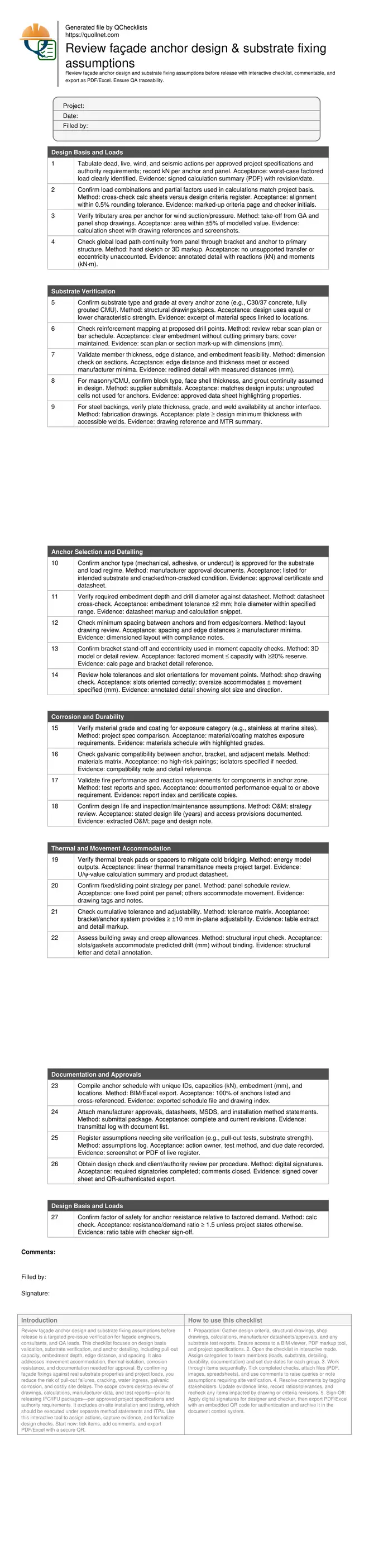
Review Façade Anchor Design and Substrate Fixing Assumptions
Definition: Review façade anchor design and substrate fixing assumptions before release ensures engineers, façade consultants, and QA managers validate loads, substrates, and anchor details prior to issuing IFC/IFU packages.
- Verify loads, substrates, and anchor capacities match project specifications.
- Reduce rework by catching unsafe embedment, spacing, and edge distances.
- Standardize approvals with documented calculations, drawings, and test evidence.
- Interactive, commentable, export, QR code for authenticated sign‑off.
Review façade anchor design and substrate fixing assumptions before release is a targeted pre-issue verification for façade engineers, consultants, and QA leads. This checklist focuses on design basis validation, substrate verification, and anchor detailing, including pull-out capacity, embedment depth, edge distance, and spacing. It also addresses movement accommodation, thermal isolation, corrosion resistance, and documentation needed for approval. By confirming façade fixings against real substrate properties and project loads, you reduce the risk of pull-out failures, cracking, water ingress, galvanic corrosion, and costly site delays. The scope covers desktop review of drawings, calculations, manufacturer data, and test reports—prior to releasing IFC/IFU packages—per approved project specifications and authority requirements. It excludes on-site installation and testing, which should be executed under separate method statements and ITPs. Use this interactive tool to assign actions, capture evidence, and formalize design checks. Start now: tick items, add comments, and export PDF/Excel with a secure QR.
- Confirm design loads, substrate properties, and anchor capacities align, then document embedment, spacing, and edge distances. Early, evidence-based checks avoid unsafe assumptions, reduce RFI churn, and enable clean IFC issue with traceable inputs.
- Validate corrosion protection, thermal breaks, and movement strategies so brackets and anchors accommodate service actions without overstress. Captured approvals and product datasheets streamline procurement and prevent mid-construction redesigns and delays.
- Interactive online checklist with tick, comment, and export features secured by QR code. Assign owners, attach calculations and drawings, and produce a signed, time-stamped record suitable for internal QA and authority submissions.
Design Basis and Loads
Substrate Verification
Anchor Selection and Detailing
Corrosion and Durability
Thermal and Movement Accommodation
Documentation and Approvals
Design Basis and Loads
Establishing design basis and verifying real substrates
Strong façade anchors start with sound inputs. Confirm dead, live, wind, and seismic actions against the design criteria and ensure the worst-case combination is used. Then align tributary areas and reactions by panel with the shop drawings. Substrates matter: concrete grade, member thickness, and edge distances often differ from assumptions made early in design. Reinforcement may obstruct embedment, and CMU grout conditions can vary by elevation. Early coordination with the structural engineer reduces surprises. Where uncertainty remains, specify targeted site verification, such as rebar scanning or proof pull-out tests, and capture it in an assumptions register with owners and dates. Acceptance cues include clearly tabulated kN loads per anchor, substrate strengths not lower than those used in calculations, and documented feasibility for drilling and embedment at each location. A concise load-path sketch demonstrating how actions transfer to the primary structure helps reviewers understand and approve the intent quickly.
- Tabulate worst-case factored loads per anchor in kN.
- Match substrate strength and geometry to design inputs.
- Prove embedment feasibility with dimensions and scans.
- Record uncertainties with action owners and dates.
Detailing anchors for capacity, durability, and movement
Anchor selection should follow the substrate and demand: mechanical, adhesive, or undercut systems each have limits. Confirm embedment depth and hole diameter from current datasheets and check spacing and edge distances. Bracket stand-offs create lever arms; verify moment capacities include eccentricity and that fixed versus sliding points are clearly defined. Corrosion and fire performance can be decisive: confirm materials suit the exposure category and that dissimilar metals are isolated. Thermal breaks reduce cold bridging without compromising capacity; verify energy model outputs. Acceptance cues include resistance-to-demand ratios of at least 1.5, spacing and edge distances meeting manufacturer minima, and documented reserves for combined shear, tension, and moment. Movement slots must accommodate predicted thermal, creep, and sway displacements without binding. Capture each decision with drawing references, calculations, and product approvals so procurement and site teams can proceed confidently.
- Verify embedment and drill sizes from current datasheets.
- Check spacing and edge distances meet minima.
- Confirm eccentricity and lever-arm effects are included.
- Specify thermal breaks and galvanic isolation.
Traceability, approvals, and targeted site verification
Before issuing IFC/IFU, compile an anchor schedule with unique IDs, capacities, embedment, and locations tied to drawings. Attach manufacturer approvals, method statements, MSDS, and any test reports. Maintain an assumptions register for items requiring site confirmation—such as substrate strength checks or proof pull tests—and assign accountable owners with due dates. Use an interactive workflow to comment, resolve queries, and capture checker sign-offs. Export a QR-authenticated package so stakeholders can confirm provenance. Acceptance cues include complete signatures, closed comments, and consistent revisions across drawings, calculations, and submittals. This disciplined documentation reduces RFIs, accelerates authority reviews, and protects warranties by showing that façade fixings were designed against verified conditions and that residual risks are clearly managed through controlled site testing after release.
- Anchor schedule covers 100% of locations.
- All approvals current and referenced.
- Assumptions log assigns owners and dates.
- QR-authenticated export proves document integrity.
How to Use the Interactive Checklist
- Preparation: Gather design criteria, structural drawings, shop drawings, calculations, manufacturer datasheets/approvals, and any substrate test reports. Ensure access to a BIM viewer, PDF markup tool, and project specifications.
- Open the checklist in interactive mode. Assign categories to team members (loads, substrate, detailing, durability, documentation) and set due dates for each group.
- Work through items sequentially. Tick completed checks, attach files (PDF, images, spreadsheets), and use comments to raise queries or note assumptions requiring site verification.
- Resolve comments by tagging stakeholders. Update evidence links, record ratios/tolerances, and recheck any items impacted by drawing or criteria revisions.
- Sign-Off: Apply digital signatures for designer and checker, then export PDF/Excel with an embedded QR code for authentication and archive it in the document control system.
Call to Action
- Start Checklist Tick off tasks, leave comments on items or the whole form, and export your completed report to PDF or Excel—with a built-in QR code for authenticity.
- Download Excel - Façade Anchor Design & Substrate Assumptions Review
- Download PDF - Façade Anchor Design & Substrate Assumptions Review
- View Image - Façade Anchor Design & Substrate Assumptions Review
Cite & Embed
“Façade Anchor Design & Substrate Assumptions Review by Quollnet”
with a link to
this source page.
FAQ
Question: When should proof pull-out tests be specified for façade anchors?
Question: What if reinforcement conflicts with the required embedment depth?
Question: How do I handle thermal movement and building sway in anchor design?
Question: Who must sign off the checklist before issuing IFC/IFU drawings?
Related Articles
Broader reading and guidance connected to this checklist topic.
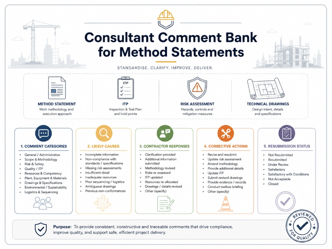
Consultant Comment Bank For Method Statements


Related Checklists
Keep the workflow moving with nearby templates chosen from similar checklist content.