Review Façade Bracket Design and Adjustment Allowances Before Issue
Definition: Review façade bracket design and adjustment allowances before issue equips façade engineers, detailers, and QA leads to verify bracket sizing, fixings, tolerances, and on-site adjustability prior to IFC or fabrication release.
- Confirm loads, materials, and geometry align with approved design basis.
- Validate fixings, edge distances, and substrate capacity with evidence.
- Set practical adjustment ranges and access clearances to avoid rework.
- Use interactive, commentable steps; export, archive, and verify via QR code.
Review façade bracket design and adjustment allowances before issue is a focused pre-issue quality step for façade engineers, detailers, and coordinators. This checklist concentrates on facade support brackets, fixing layouts, and tolerance allowances that ensure panels install accurately and safely. You will verify design loads, bracket geometry, substrate anchors, and thermal isolators against the approved project specifications and authority requirements. It also confirms practical bracket adjustability, shimming ranges, slot lengths, and access for tools and sealing so installation crews can align units without drilling new holes or compromising edge distances. By addressing corrosion protection, galvanic isolation, and interface continuity with air/water barriers and firestops, you reduce rework, avoid site delays, and improve handover documentation. Use this interactive page to tick off each requirement, attach calculations, mark up details, capture mockup photos, and assign actions in comments. When complete, export to PDF/Excel with a secure QR for audit and site verification.
- Verify loads, bracket geometry, fixings, and materials early to prevent misaligned anchors, excessive deflection, or corrosion risks. The checklist emphasizes evidence-backed calculations, manufacturable details, and practical access clearances so installation can proceed without re-drilling, slotting on site, or compromising substrate integrity.
- Set realistic adjustment allowances using a tolerance stack-up anchored to the latest structural survey. Defined vertical, horizontal, and in/out ranges, together with shims and slots, create buffer for substrate deviations while maintaining edge distances and weather, fire, and air barrier continuity throughout the façade zone.
- Interactive online checklist with tick, comment, and export features secured by QR code. Teams can attach calculation packs, anchor software reports, marked drawings, and mockup photos; assign actions; track approvals; and archive a verifiable pre-issue record that streamlines fabrication release and field installation sequencing.
- Comprehensive documentation control links bracket IDs to elevations and coordinates, embeds torque specifications and slot dimensions on drawings, and assembles datasheets and approvals. Clear release gates with digital signatures ensure only complete, coordinated information advances to IFC or fabrication, reducing costly revisions later.
Design Basis and Loads
Bracket Geometry and Capacity
Fixings and Substrate
Adjustment Allowances and Buildability
Documentation and Approval
Establishing the Design Basis
A robust bracket review begins with a clear, approved design basis. Confirm wind pressures, dead loads, maintenance allowances, and eccentricities for each elevation and typical unit. Tie these inputs to the current structural model and survey to avoid relying on superseded data. Next, check materials and corrosion protection: stainless steel grades or galvanized coatings must suit the exposure category. Validate thermal isolators for compressive capacity and creep at service temperatures, then verify bearing pressures at all interfaces. Movement allowances for temperature, settlement, and interstorey drift must be absorbed by slot lengths and sliding connections, not transferred into brittle finishes. Record each decision in the calculation pack, referencing the drawing where the requirement is shown. This structured evidence lets reviewers retrace assumptions and installers trust that brackets will work first time on site.
- Use signed load summaries linked to current models.
- Cross-check materials and coatings with exposure category.
- Isolators sized for service pressure and creep limits.
- Movement absorbed by slots, not finishes or substrate.
- Reference every check directly on affected drawings.
Practical Adjustment Strategy
Adjustment is not guesswork; it is a tolerance budget grounded in survey data. Combine structural survey deviations with fabrication tolerances and installation variances to set vertical, horizontal, and in/out ranges. Define shimming packs using non-compressible materials and size slot lengths to cover predicted movement plus reserve. Maintain minimum edge distances when sliding connections are used, and ensure access for tools without damaging adjacent air, water, and fire barriers. Mockups reveal whether installers can realistically reach bolts, apply torque, and seal openings. Document tool clearance requirements and ensure sealant continuity around brackets. The aim is field-friendly details: installers should align panels without re-drilling, overslotting, or compromising anchor performance, even when substrates are uneven.
- Base ranges on survey plus fabrication and install tolerances.
- Specify non-compressible shims with labeled increments.
- Protect minimum edge distances while allowing sliding.
- Prove access and sealing in a physical or VR mockup.
- Reserve capacity beyond measured worst case.
Interfaces, Evidence, and Release Control
Façade brackets live within a tight envelope of thermal breaks, air/water barriers, insulation, and firestops. Coordinate bracket footprints to avoid obstructing drainage paths and to preserve continuous membranes and fire barriers. Detail galvanic isolation where dissimilar metals meet. Embed torque values, slot dimensions, and bracket IDs in drawings so field teams have single-source information. Assemble the full evidence pack: structural calculations, anchor software outputs, datasheets, and annotated mockup photos. Then apply rigorous release control. Use a pre-issue checklist to confirm completeness, gain digital signatures from responsible engineers and contractors, and archive with a transmittal. A QR-secured export lets site supervisors verify the exact version used during installation.
- Maintain air, water, thermal, and fire barrier continuity.
- Show torque and slot data on GA and detail sheets.
- Isolate dissimilar metals to prevent corrosion cells.
- Archive calculations, reports, and mockup photos.
- Release only after digital signatures and QR export.
How to Use This Interactive Checklist
- Preparation: gather drawings, structural model, latest survey, project specifications, manufacturer datasheets, calculation packs, and mockup photos. Install anchor design software and open a BIM/CAD viewer for overlays.
- Open the checklist, select the project and elevation, then start interactive mode. Confirm the revision aligns with the latest design brief and transmittal.
- Work through items sequentially. Tick completed checks, attach calculation excerpts, software reports, and marked-up details as evidence for each requirement.
- Use comments to raise queries, tag responsible parties, and set due dates. Convert unresolved comments into RFIs where needed and link references.
- Export progress or final output as PDF/Excel with a secure QR code. Share the export with fabrication, site teams, and approvers.
- Sign-Off: obtain digital signatures from the façade lead, structural checker, and contractor representative. Archive the signed export and evidence pack in the project CDE.

Call to Action
- Start Checklist Tick off tasks, leave comments on items or the whole form, and export your completed report to PDF or Excel—with a built-in QR code for authenticity.
- Download Excel - Façade Bracket Design Review Pre-Issue
- Download PDF - Façade Bracket Design Review Pre-Issue
- View Image - Façade Bracket Design Review Pre-Issue
Cite & Embed
“Façade Bracket Design Review Pre-Issue by Quollnet”
with a link to
this source page.
FAQ
Question: How much adjustment should I allow in façade brackets?
Question: What if the substrate survey shows larger deviations than expected?
Question: Do I need calculations for every bracket type and location?
Question: How do I coordinate brackets with fire and air/water barriers?
Related Articles
Broader reading and guidance connected to this checklist topic.


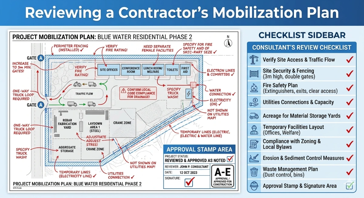
How To Review a Contractor’s Mobilization Plan

Related Checklists
Keep the workflow moving with nearby templates chosen from similar checklist content.