Façade bracket locations and tolerances inspection (pre-framing)
Definition: Inspect façade bracket locations and tolerances before framing installation for site engineers and façade supervisors, ensuring precise setting out, fixings, and alignment within specified limits before rails are fitted.
- Verify bracket grid, anchors, and isolators match approved submittals.
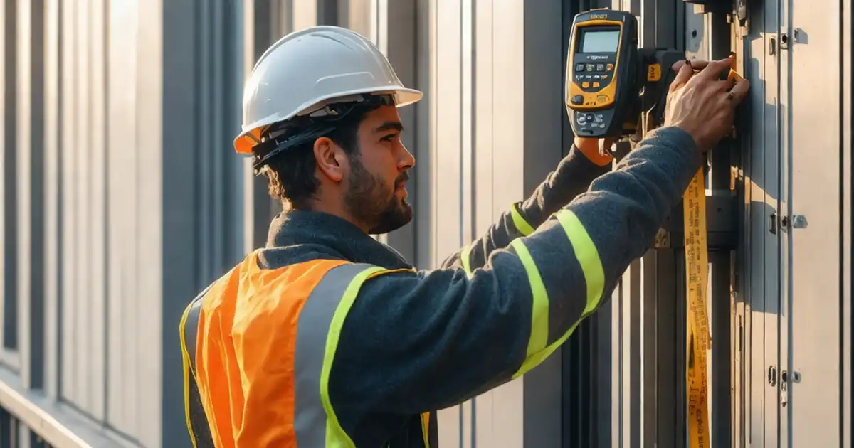
- Measure projection, spacing, plumb, and in-plane alignment within millimetre tolerances.
- Capture photos, torque logs, coordinates, and pull-out results for evidence.
- Interactive, commentable checklist with export and QR code verification.
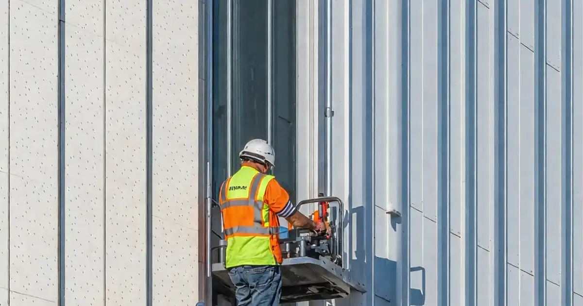
Inspect façade bracket locations and tolerances before framing installation is a focused quality gate that prevents layout errors from propagating into the rail and cladding system. This pre-framing inspection confirms bracket setting out, rainscreen support angles, and cladding support brackets are positioned and aligned to the latest drawings. You will validate survey control, offsets, substrate suitability, anchor edge distances, and allowable adjustment ranges, then confirm bracket projection, plumb, and in-plane alignment against stated limits. Getting these checks right averts misaligned rails, panel clashes, gaskets under stress, water-management failures, and costly rework at height. The outcome is a verifiable, millimetre-true foundation for the façade rails to install quickly and safely, per approved project specifications and authority requirements. Use this interactive checklist to guide field steps, attach photos with rulers and digital levels, log torque and pull-out results, and record approvals. Tick items, add comments, and export your evidence as PDF/Excel with a secure QR link.
- Confirming setout against current drawings, coordinates, and datums reduces cumulative error before rails are installed. By locking bracket locations, spacing, and projections within tight tolerances, you avoid downstream shimming, panel cut-backs, and schedule impacts, while ensuring compliance with the project specification and authority requirements.
- Systematically checking substrate condition, edge distances, embedment depth, and representative pull-out capacities verifies anchors are suitable and correctly installed. Documenting test values, torque logs, and batch numbers provides a clear audit trail and simplifies approvals, handovers, and any later investigations or warranty claims.
- Verifying plumb, level, and in-plane alignment across bays ensures rails will seat without stress, preserving thermal breaks and waterproofing details. Consistent photographic evidence with scales and digital readings demonstrates acceptance criteria have been met and helps teams spot trends that require early corrective action.
- Interactive online checklist with tick, comment, and export features secured by QR code.
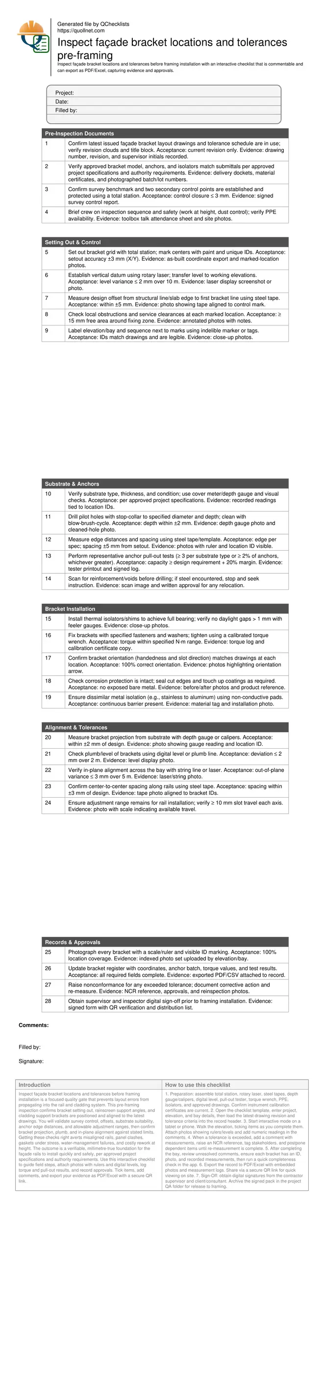
Pre-Inspection Documents
Setting Out & Control
Substrate & Anchors
Bracket Installation
Alignment & Tolerances
Records & Approvals
Why bracket location accuracy matters before rails go in
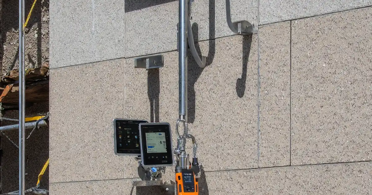
Brackets form the fixed backbone of the façade support system, so small errors multiply when rails and panels are added. Before framing installation, confirm the grid aligns with the latest drawings, control points are verified, and offsets from slab edges or structural lines are correct. Millimetre deviations at brackets can produce misaligned rails, stressed joints, telegraphed panel steps, and compromised weathering details. Catching issues early allows simple re-drilling or shimming without dismantling installed rails. Acceptance cues include clear, legible location IDs, coordinates within ±3 mm, and level transfer within ±2 mm over 10 m. Evidence should be visual and numeric: photos with scales, digital level readings, torque logs, and pull-out test printouts. Keep the scope strictly to bracket locations and tolerances; defer thermal movement joint checks or panel tolerances to later phases. Consistency across bays enables efficient rail installation and predictable finish quality, while providing a robust audit trail for approvals and warranty.
- Use a total station to fix accurate grid coordinates.
- Lock vertical datums before measuring projections.
- Photograph every bracket with a visible scale.
- Record numeric readings, not only visual checks.
Reliable methods, tools, and acceptance cues on site
Use a calibrated total station for setout, a rotary laser for datums, steel tapes for offsets, and digital levels or string lines for plumb/level checks. Measure bracket projection with depth gauges or calipers, and verify anchor depth using stop-collars and depth probes. For anchors, confirm edge distances and spacing are within tolerance and perform representative pull-out tests, logging kN values tied to location IDs. Maintain isolators and coatings to prevent galvanic corrosion and premature wear. Acceptance cues include setout ±3 mm, projection ±2 mm, out-of-plumb ≤ 2 mm over 2 m, and in-plane variance ≤ 3 mm over 5 m, unless stricter project limits apply. Document everything: batch numbers, torque values, and calibration certificates. When encountering rebar or voids, stop and obtain written instruction before relocating. These practices reduce rework and provide defensible evidence for sign-off per approved project specifications and authority requirements.
- Calibrate instruments and keep certificates accessible.
- Tie every reading to a unique location ID.
- Clean drill holes to achieve full anchor performance.
- Stop and escalate when hitting unexpected reinforcement.
Documentation, traceability, and quick approvals
Traceable records accelerate approvals and safeguard project outcomes. Structure your photo evidence by elevation and bay, with each image showing the bracket ID and a physical scale. Keep a live bracket register that captures coordinates, fastener batches, torque values, and pull-out test results, then export it alongside photos. Nonconformances should be raised immediately for any tolerance breach, with corrective actions tracked and verified by re-measurement. Digital signatures from contractor and client/consultant create a clear acceptance point before rails arrive on site. The aim is to provide a concise, complete package that shows positions, tolerances, and fixings comply with the approved specification. Using an interactive checklist standardises the process, reduces omissions, and produces consistent deliverables that can be referenced during rail installation, panel setting, and final QA closeout.
- Index photos to elevation, bay, and location ID.
- Export registers to PDF/Excel for review.
- Secure digital signatures with QR verification.
- Raise NCRs and re-measure after correction.
How to use this interactive pre-framing bracket inspection checklist
- Preparation: assemble total station, rotary laser, steel tapes, depth gauge/calipers, digital level, pull-out tester, torque wrench, PPE, isolators, and approved drawings. Confirm instrument calibration certificates are current.
- Open the checklist template, enter project, elevation, and bay details, then load the latest drawing revision and tolerance criteria into the record header.
- Start interactive mode on a tablet or phone. Walk the elevation, ticking items as you complete them. Attach photos showing rulers/levels and add numeric readings in the comments.
- When a tolerance is exceeded, add a comment with measurements, raise an NCR reference, tag stakeholders, and postpone dependent items until re-measurement is complete.
- After completing the bay, review unresolved comments, ensure each bracket has an ID, photo, and recorded measurements, then run a quick completeness check in the app.
- Export the record to PDF/Excel with embedded photos and measurement logs. Share via a secure QR link for quick viewing on site.
- Sign-Off: obtain digital signatures from the contractor supervisor and client/consultant. Archive the signed pack in the project QA folder for release to framing.
Call to Action
- Start Checklist Tick off tasks, leave comments on items or the whole form, and export your completed report to PDF or Excel—with a built-in QR code for authenticity.
- Download Excel - Façade Bracket Location & Tolerance Inspection (Pre-Framing)
- Download PDF - Façade Bracket Location & Tolerance Inspection (Pre-Framing)
- View Image - Façade Bracket Location & Tolerance Inspection (Pre-Framing)
Cite & Embed
“Façade Bracket Location & Tolerance Inspection (Pre-Framing) by Quollnet”
with a link to
this source page.
FAQ
Question: What tolerances should I use if the project specification is silent?
Question: How many anchor pull-out tests are required before framing starts?
Question: What should I do if drilling hits reinforcement or a void?
Question: Do weather and temperature affect bracket inspection results?
Question: Who signs off the bracket location inspection before framing?
Related Articles
Broader reading and guidance connected to this checklist topic.


Master Construction Project Cashflow With Cashflowpot

Improve Your Project Handover Process With Snag List Tracking App
Related Checklists
Keep the workflow moving with nearby templates chosen from similar checklist content.