Test façade anchor pull-out resistance in representative substrate
Definition: Test façade anchor pull-out resistance in representative substrate to validate design capacities and installation methods for cladding fixings, guiding site engineers through safe, standardized on-site tension proof and ultimate tests.
- Plan tests in representative base materials matching production conditions.
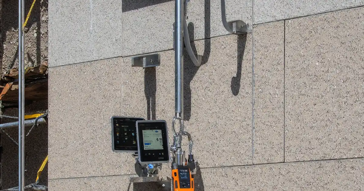
- Set up calibrated pull tester and reaction frame for coaxial loading.
- Record load–displacement data, failure mode, and photographic evidence.
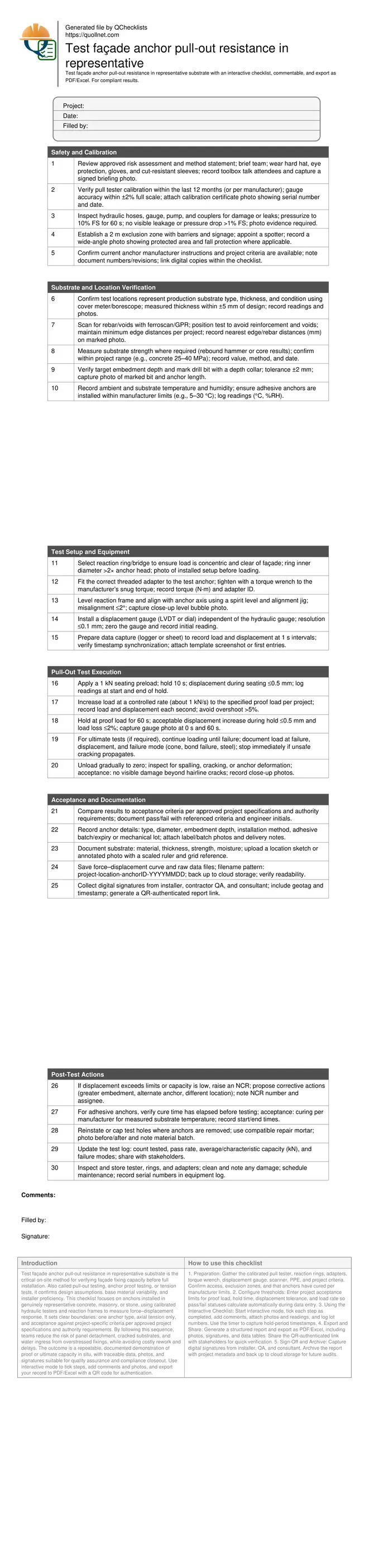
- Interactive, commentable checklist with export and QR code verification.
Test façade anchor pull-out resistance in representative substrate is the critical on-site method for verifying façade fixing capacity before full installation. Also called pull-out testing, anchor proof testing, or tension tests, it confirms design assumptions, base material variability, and installer proficiency. This checklist focuses on anchors installed in genuinely representative concrete, masonry, or stone, using calibrated hydraulic testers and reaction frames to measure force–displacement response. It sets clear boundaries: one anchor type, axial tension only, and acceptance against project-specific criteria per approved project specifications and authority requirements. By following this sequence, teams reduce the risk of panel detachment, cracked substrates, and water ingress from overstressed fixings, while avoiding costly rework and delays. The outcome is a repeatable, documented demonstration of proof or ultimate capacity in situ, with traceable data, photos, and signatures suitable for quality assurance and compliance closeout. Use interactive mode to tick steps, add comments and photos, and export your record to PDF/Excel with a QR code for authentication.
- Plan and execute pull-out tests in base materials that match production conditions by thickness, strength, and moisture content, using a defined sampling plan to capture variability across elevations, orientations, and substrate types, ensuring results accurately represent the installed façade.
- Set up a calibrated hydraulic pull tester with the correct reaction frame and adapters for coaxial loading. Control the load rate, measure displacement to 0.1 mm, and document proof or ultimate capacity with clear hold periods to prevent dynamic spikes and protect the substrate.
- Record comprehensive metadata: anchor type, diameter, embedment depth, adhesive batch or mechanical lot, substrate properties, environmental conditions, and precise locations. Store force–displacement curves, photos, and signatures to create a defensible, audit-ready quality record for acceptance and future maintenance decisions.
- Interactive online checklist with tick, comment, and export features secured by QR code. Use it to streamline team collaboration, standardize procedures across shifts, and produce consistent PDF/Excel reports that meet project requirements without duplicated paperwork or missing evidence.
Safety and Calibration
Substrate and Location Verification
Test Setup and Equipment
Pull-Out Test Execution
Acceptance and Documentation
Post-Test Actions
Choose Representative Substrates and Test Locations
Representative substrate selection determines whether pull-out test results are meaningful. Sample across elevations, exposures, and construction sequences to capture variability in concrete maturity, masonry unit strength, or bedding quality. Use a ferroscan or GPR to avoid rebar and voids, and verify thickness with a cover meter or borescope. Where specifications require, confirm compressive strength (rebound hammer correlation or core tests) so tests reflect design assumptions. Mark each location on drawings and the façade with non-permanent identifiers. For anchors installed into adhesive-filled holes, record substrate and ambient temperatures because cure time and bond performance are temperature-dependent. Establish minimum edge distances per project requirements to prevent splitting or localized failure that does not represent production conditions. Finally, agree on proof or ultimate test objectives with the engineer so loading limits and safety margins are clear before equipment is set up.
- Distribute tests across different elevations and orientations.
- Confirm thickness within ±5 mm at each test point.
- Avoid reinforcement and voids using scanning before drilling.
- Record substrate strength values and test methods.
- Mark locations on drawings and site photos.
Set Up Equipment and Apply Controlled Loading
Axial, concentric loading is essential for reliable pull-out results. Select a reaction ring or bridge that clears façade irregularities and centers over the anchor without bearing on weak finishes. Fit the correct threaded adapter and tighten with a torque wrench to prevent thread damage or bending moments. Level the frame within 2° and install a separate displacement gauge (0.1 mm resolution) to measure movement independently of hydraulic pressure. Apply a small preload to seat the assembly, then increase load at a steady rate—typically about 1 kN/s—while recording paired load–displacement readings. For proof tests, hold the specified load for 60 s and confirm displacement stabilizes within the acceptable limit. For ultimate tests, proceed cautiously to failure, documenting the failure mode and stopping immediately if unsafe cracking propagates. Always unload gradually to prevent rebound or secondary damage.
- Keep misalignment within 2° for axial loading.
- Use a displacement gauge with 0.1 mm resolution.
- Control load rate at about 1 kN/s.
- Hold proof load for 60 s minimum.
Interpret Results and Capture Evidence
Acceptance hinges on meeting project-specified capacities and deformation limits, not just reaching a number on the gauge. Compare the recorded force–displacement curve to expected behavior: stable displacement at proof load, or well-defined capacity and ductile failure at ultimate. Log all metadata—anchor type and size, embedment depth, adhesive batch or mechanical lot, substrate conditions, and exact location. Photos should show the setup, gauge readings at key times, and post-test condition. Name files consistently and back them up to a shared repository. Where results are low, raise an NCR and propose remedies such as deeper embedment, larger diameter, or alternative anchor systems. Secure digital sign-offs from the installer, QA, and the engineer so the test is auditable and linked to the construction record.
- Compare capacity and displacement to project criteria.
- Record failure mode with clear photographs.
- Save raw data and force–displacement plots.
- Collect digital signatures with geotags.
How to Use This Interactive Pull-Out Test Checklist
- Preparation: Gather the calibrated pull tester, reaction rings, adapters, torque wrench, displacement gauge, scanner, PPE, and project criteria. Confirm access, exclusion zones, and that anchors have cured per manufacturer limits.
- Configure thresholds: Enter project acceptance limits for proof load, hold time, displacement tolerance, and load rate so pass/fail statuses calculate automatically during data entry.
- Using the Interactive Checklist: Start interactive mode, tick each step as completed, add comments, attach photos and readings, and log lot numbers. Use the timer to capture hold-period timestamps.
- Export and Share: Generate a structured report and export as PDF/Excel, including photos, signatures, and data tables. Share the QR-authenticated link with stakeholders for quick verification.
- Sign-Off and Archive: Capture digital signatures from installer, QA, and consultant. Archive the report with project metadata and back up to cloud storage for future audits.
Call to Action
- Start Checklist Tick off tasks, leave comments on items or the whole form, and export your completed report to PDF or Excel—with a built-in QR code for authenticity.
- Download Excel - Façade Anchor Pull-Out Resistance Test
- Download PDF - Façade Anchor Pull-Out Resistance Test
- View Image - Façade Anchor Pull-Out Resistance Test
Cite & Embed
“Façade Anchor Pull-Out Resistance Test by Quollnet”
with a link to
this source page.
FAQ
Question: How many pull-out tests should be performed to represent a façade area?
Question: What is the difference between a proof test and an ultimate test?
Question: Can I test adhesive anchors before full cure?
Question: What if the anchor fails or displacement exceeds the limit during a proof test?
Question: Can the same anchor be used in production after a pull-out test?
Related Articles
Broader reading and guidance connected to this checklist topic.


Is It Important To Customize Your Qr Code And How To Do It?

Related Checklists
Keep the workflow moving with nearby templates chosen from similar checklist content.