Undercut Anchor Connections Inspection for Stone Cladding
Definition: Inspect stone cladding kerf, dowel, or undercut anchor connections with a rigorous, field-ready checklist for façade engineers and installers, focusing on undercut anchor systems, acceptance criteria, documentation, and photographic evidence.
- Targeted to undercut anchors in ventilated stone façades and rainscreens
- Defines field tolerances, tools, and acceptance cues for safe installation
- Captures traceable measurements, approvals, lot numbers, and location-tagged photos
- Interactive, commentable checklist; export to PDF/Excel with QR code
Inspect stone cladding kerf, dowel, or undercut anchor connections to prevent panel detachment, cracking, and moisture ingress while assuring durable façade performance. This checklist specifically covers undercut anchor connections for ventilated stone cladding, touching related terms such as façade anchorage and mechanical fixing but excluding kerf and dowel procedures from the step list. You’ll verify substrates, hole geometry, anchor installation torque, panel alignment, and joint control, all while capturing calibrated readings, lot numbers, and photographic evidence. By structuring acceptance criteria around manufacturer data and per approved project specifications and authority requirements, the process reduces rework, protects stone integrity, and secures traceability for audits and warranties. Use the interactive mode to tick items, add comments with photos, and instantly export results as PDF/Excel with embedded QR for authenticity.
- Use this inspection to verify undercut anchor connections in stone cladding, from substrate survey and hole geometry through torque application and panel alignment. The process mitigates spalling, loosening, and misalignment, reduces rework, and secures compliance with approved project specifications and authority requirements while maintaining full traceability.
- The checklist details tools, tolerances, and evidence for each task: laser surveys, calibrated torque wrenches, cleaning sequences, geometry gauges, joint spacers, and proof-load testing. It also records lot numbers, heat numbers, photos, and signatures, building a robust as-built dossier that accelerates approvals and future maintenance planning.
- Interactive online checklist with tick, comment, and export features secured by QR code.
Pre-Installation Documentation
Substrate and Layout
Undercut Anchor Installation
Stone Panel Preparation
Installation and Alignment
Testing and Handover
What good undercut anchor installation looks like
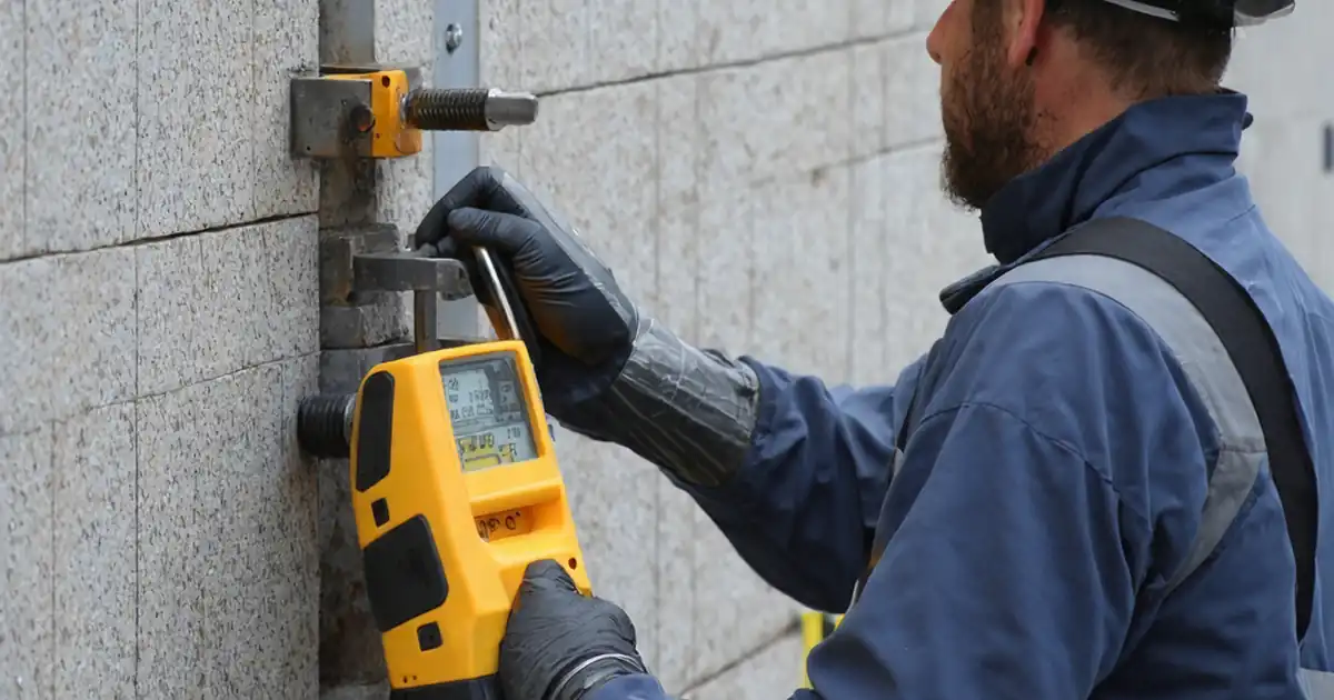
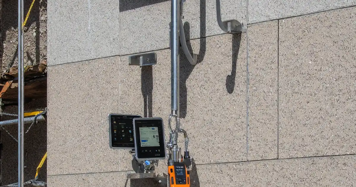
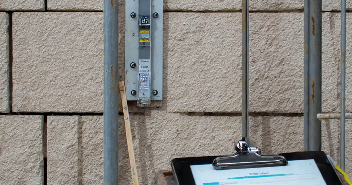
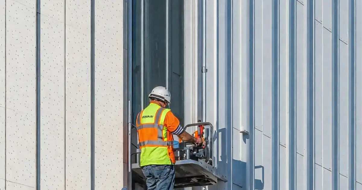
A successful undercut anchor connection preserves the stone’s integrity while transferring loads safely into the substructure. Start with a verified substrate, then drill, clean, and form the undercut to the exact geometry specified by the manufacturer. Use the installation torque range as a measurable acceptance cue, and confirm full seating of hardware during dry fits. During hanging, control stand-off and joints with lasers, spacers, and calibrated gauges. Document every step: tool IDs, batch numbers, measurements, and labeled photos. These records build defensible traceability for handover and future maintenance. Finally, confirm performance with proof-load tests on a defined sample. Passing anchors show no slip, cracking, or rotation at the required load. Consistency across locations is as important as individual readings to ensure the façade behaves predictably under service conditions.
- Use stop collars and geometry gauges for repeatable drilling.
- Record torque values and tool calibration IDs.
- Measure joint widths and stand-off with gauges.
- Capture close-up photos before panels conceal anchors.
Common issues and how to prevent them
Frequent problems include dust-filled bores, incomplete undercuts, over-torqued fasteners, and inadequate edge distances. Dust undermines friction and bearing; solve it with a brush–blow–vacuum cycle and borescope checks. Incomplete undercuts come from worn cutters or misaligned rigs; track cutter wear and use guides. Over-torquing can fracture stone or damage sleeves; always use a calibrated torque wrench and adhere to the manufacturer’s range. Edge distance errors often arise from poor templating; ensure precise setting-out and verify with steel rules before drilling. Finally, uncontrolled shimming can create point loading and telegraph through the stone; use correct isolation pads and check full bearing. Addressing these risks at source prevents rework, protects finishes, and maintains system capacity under wind, thermal, and seismic actions.
- Clean, inspect, and verify undercuts every hole.
- Replace worn cutters before tolerance drift.
- Use calibrated torque tools; avoid guesses.
- Measure edge distances prior to drilling.
Field testing, documentation, and handover essentials
Proof-load testing validates installation quality and confirms that the system meets the approved test plan. Select representative anchors across orientations, elevations, and installers. Use a calibrated tester with a reaction frame that does not load adjacent components. Record test loads in kN, displacement observations, and pass/fail outcomes. Complement tests with complete documentation: shop drawings, certificates, torque logs, lot numbers, and as-built locations. Export a single dossier, digitally signed and QR-authenticated, to streamline approvals and future audits. Comprehensive records shorten closeout cycles, enable rapid root-cause analysis if issues arise, and provide clear inputs for maintenance inspections over the façade’s life.
- Test to the approved plan; record kN and displacement.
- Distribute tests across elevations and installers.
- Export a signed, QR-authenticated dossier.
- Log lot numbers and heat marks for traceability.
How to use this interactive inspection checklist
- Preparation: Gather approved drawings, anchor data sheets, mock-up reports, and calibration certificates. Prepare laser, torque wrench, pull tester, borescope, gauges, PPE, and photo-capable device.
- Set up the work area: confirm access, lighting, and safe platforms. Tag inspection zones and ensure panels, anchors, and tools are clearly labeled for traceability.
- Start interactive mode: open the checklist, select location/elevation, and enable tick and comment features. Attach photos and measurements to each item as you progress.
- Record evidence: input measured dimensions, torque (Nm), loads (kN), lot numbers, and tool IDs. Use standardized notes for nonconformities and assign actions.
- Resolve comments: collaborate with installers and QC to address findings. Reinspect closed items and capture before/after photos for the record.
- Export: generate a commentable PDF/Excel report with embedded QR authentication, including photos, signatures, and timestamps for client and authority submissions.
- Sign-Off: obtain digital signatures from the inspector, contractor, and client. Archive the final dossier in the project CDE with version control.
Call to Action
- Start Checklist Tick off tasks, leave comments on items or the whole form, and export your completed report to PDF or Excel—with a built-in QR code for authenticity.
- Download Excel - Stone Cladding Undercut Anchor Inspection
- Download PDF - Stone Cladding Undercut Anchor Inspection
- View Image - Stone Cladding Undercut Anchor Inspection
Cite & Embed
“Stone Cladding Undercut Anchor Inspection by Quollnet”
with a link to
this source page.

FAQ
Question: What’s the difference between kerf, dowel, and undercut anchors, and why focus on undercut?
Question: How do I set acceptance criteria without specific code clauses?
Question: What should I do if a proof-load test shows slip or stone cracking?
Question: How can I prevent over-torquing anchors during installation?
Related Articles
Broader reading and guidance connected to this checklist topic.


Improve Your Project Handover Process With Snag List Tracking App
Related Checklists
Keep the workflow moving with nearby templates chosen from similar checklist content.