Install vibro-replacement stone columns: inspection checklist
Definition: Install vibro-replacement stone columns inspection checklist for site engineers and QC managers to verify probe logs, stone take, spacing tolerances, densification acceptance, and complete as-built documentation.
- Verify logs, spacing, and stone take against approved design tolerances.
- Monitor lift sequencing to achieve reliable ground densification acceptance.
- Capture photos, weigh tickets, and survey files for as-built records.
- Interactive, commentable, export options with QR code verification.
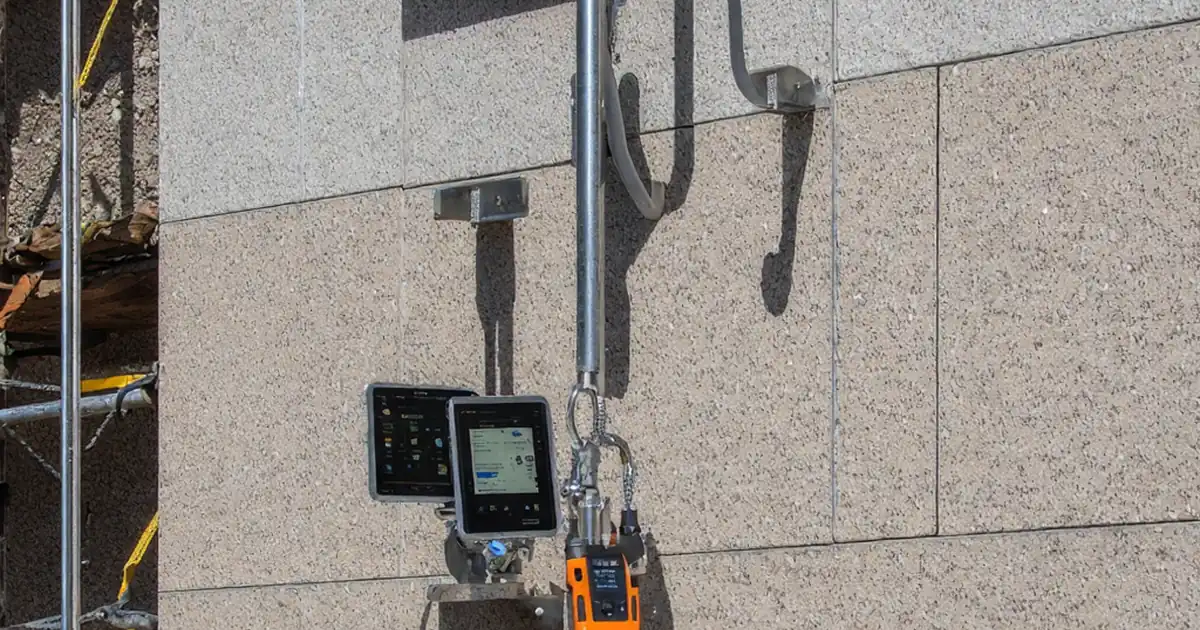
Install vibro-replacement stone columns safely and consistently with this focused inspection checklist. Also known as vibro replacement and vibro stone columns, this method densifies granular soils and forms load-sharing inclusions using clean aggregate. The scope here is production installation quality control: verifying probe logs, confirming stone take, validating location spacing, and documenting densification acceptance. Rigid inclusions (grouted or concrete elements) are explicitly excluded. Following this guide helps avoid common risks—underlength columns, insufficient bulbing, segregation of aggregate, mislocated positions, and inadequate post-treatment capacity—that can lead to settlement, differential movement, or non-compliance. You’ll capture evidence from data loggers, scales, and surveys, and align acceptance with approved project specifications and authority requirements. The outcome is a defensible as-built package proving target improvement was achieved without grout or cementitious materials. Use the interactive features to tick each step, add comments where adjustments are made, and export a complete, QR-secured PDF/Excel report for stakeholders.
- This checklist guides site teams through practical controls that matter on vibro replacement: confirming column locations, managing lift sequencing, tracking stone intake, and reading probe logs. Acceptance focuses on meeting design depth, spacing tolerances, and measurable densification metrics supported by calibrated instruments.
- Accurate stone take and clean gradation are critical for bulbing and composite stiffness. You’ll log mass per lift, compare against calculated take, and verify top-of-column elevations by survey. Post-treatment verification by CPT or load testing confirms the improved ground meets serviceability criteria set in the project specifications.
- Interactive online checklist with tick, comment, and export features secured by QR code.
- The workflow produces close-out documentation in one place: data logs, weigh tickets, calibration certificates, and as-built layouts. Clear evidence trails reduce disputes and rework, supporting timely approvals from the engineer and authority having jurisdiction while keeping the installation method strictly to stone columns, not rigid inclusions.
Pre-Construction & Submittals
Equipment & Calibration
Layout & Spacing Verification
Installation Monitoring & Probe Logs
Stone Take & Materials Control
Densification, Testing & Handover
Why probe logs, spacing, and lift control drive successful stone columns
Probe logs are the live heartbeat of vibro replacement. Depth, time, and current traces show whether the tool reached design depth, whether lifts were held long enough, and if densification increased resistance with each pass. Spacing accuracy matters just as much: column interaction and composite stiffness depend on the grid being true to design, not drifting by casual stake placement. Lift control—0.5–1.0 m segments with adequate hold time—governs bulbing and lateral confinement, which prevents voids and soft pockets. Together, these controls reduce risk of underperformance, differential settlement, or post-construction remedial programs. Calibrated instruments (depth encoder, logger, scales) provide objective proof. When deviations occur, quick feedback from the logger lets crews adjust stone feed rate, dwell time, or pull speed immediately, rather than discovering problems during final testing. The result is a traceable, defensible record of compliant production achieved without grout, in line with the approved vibro replacement method.
- Use calibrated depth encoders with ±0.10 m accuracy.
- Hold each lift for at least 10 seconds for densification.
- Maintain grid spacing within 30–50 mm horizontally.
- Trend current upward per lift to confirm bulbing.
- Capture logs at ≥1 Hz sampling frequency.
Stone take: predicting, measuring, and controlling for bulbing
Calculated stone take anticipates the mass required to form bulbs and fill densified voids. In production, weigh-belt scales and batch tickets measure actual intake per lift and per column. Deviations usually imply lift height, withdrawal speed, or aggregate quality issues. Clean, well-graded 25–75 mm angular stone interlocks and resists crushing; wet, dirty, or flaky aggregate increases fines and reduces lateral confinement. Recording per-lift mass allows targeted corrections: add hold time, slow withdrawal, or adjust lift height to recover the bulbing profile. A ±10% window against the calculated take is commonly achievable with disciplined feed control and steady power. The top-of-column elevation must meet design so the load transfer platform performs as intended. By linking each column ID to its mass record and elevation survey, you create a reliable basis for acceptance and a clear audit trail for the engineer.
- Track per-lift and total stone mass by column ID.
- Keep stone take within ±10% of calculation.
- Use clean, angular 25–75 mm aggregate only.
- Survey top elevation within ±20 mm of design.
Densification acceptance and post-treatment verification
Acceptance combines compliant production records with objective post-treatment testing. Logger trends should reveal increasing resistance with each lift and proper termination at design depth. A short test zone early in the works confirms parameters before scaling up production. After treatment, in-situ verification such as CPT or dynamic probing checks that stiffness and strength meet the design targets over representative locations, while plate load or modulus tests confirm serviceability under applied load. Surveyed as-builts demonstrate positions are within tolerance and that the surface has been restored. All results are compiled into a complete package for approval per the project specifications and authority requirements. Importantly, this checklist is specific to stone columns; grout or concrete (rigid inclusions) are not used or accepted within this scope.
- Plan and review a focused trial section first.
- Use CPT/DPH to verify target qc or N-values.
- Add plate load tests where serviceability governs.
- Submit signed as-builts with logs and calibrations.
How to use this interactive vibro replacement checklist
- Preparation: assemble IFC drawings, approved method statement, ITP, logger setup guide, calibration certificates, weigh tickets, survey gear, PPE, and a camera. Brief the crew on dry bottom-feed stone columns and exclusion of rigid inclusions.
- Using the Interactive Checklist: open the checklist on a tablet, start interactive mode, tick items as completed, and add comments where adjustments are made or issues arise.
- Attach Evidence: upload logger CSVs, calibration sheets, weigh tickets, and geotagged photos directly to the relevant item so each requirement has traceable proof.
- Export and Share: generate an export as PDF/Excel for daily reports, including comments and attachments, and distribute to the site team and engineer.
- Sign-Off: capture digital signatures from the contractor’s supervisor and the engineer, archive the QR-authenticated report in the DMS, and proceed to the next lot.

Call to Action
- Start Checklist Tick off tasks, leave comments on items or the whole form, and export your completed report to PDF or Excel—with a built-in QR code for authenticity.
- Download Excel - Vibro-Replacement Stone Columns Installation Inspection
- Download PDF - Vibro-Replacement Stone Columns Installation Inspection
- View Image - Vibro-Replacement Stone Columns Installation Inspection
Cite & Embed
“Vibro-Replacement Stone Columns Installation Inspection by Quollnet”
with a link to
this source page.
FAQ
Question: What variance is acceptable for stone take on vibro-replacement stone columns?
Question: How are probe logs used to confirm densification and depth compliance?
Question: What spacing tolerance is reasonable for stone column layout?
Question: How should groundwater be handled with dry bottom-feed vibro replacement?
Question: How can densification be proven without extensive plate load testing?
Related Articles
Broader reading and guidance connected to this checklist topic.


Improve Your Project Handover Process With Snag List Tracking App

Comprehensive Guide To Managing Variation Orders In Construction Projects
Download Excel Format Snag List

Related Checklists
Keep the workflow moving with nearby templates chosen from similar checklist content.