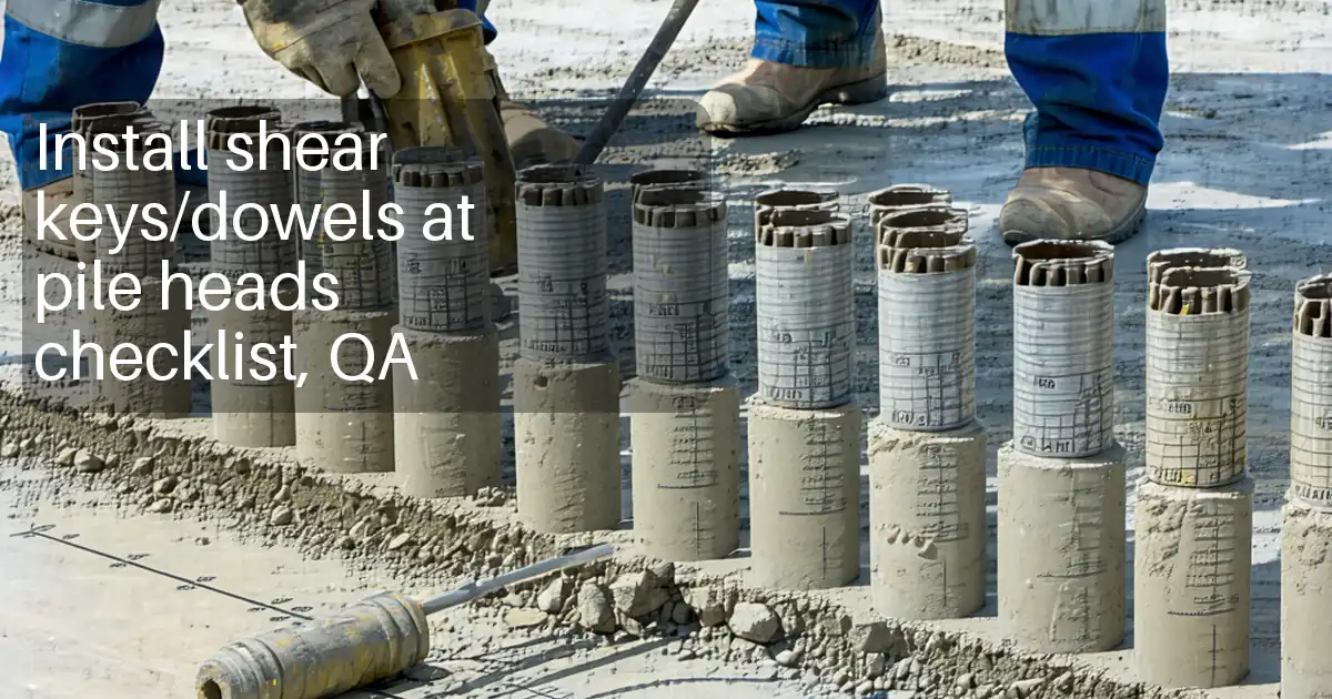
Install Mechanical Couplers at Pile Heads: QA Inspection
Definition: Install mechanical couplers at pile heads with this field-ready checklist for inspectors and foremen, verifying thread engagement, installation torque, identification markings, and preventing exposed reinforcing bars before capping or casting.
- Confirm bar alignment, thread cleanliness, and full coupler engagement.
- Apply specified torque with calibrated wrench; record N·m readings.
- Log manufacturer markings, lot traceability, and location references.
- Interactive, commentable, export to PDF/Excel, secured by QR code.
Install mechanical couplers at pile heads using this concise, field-proven process to control engagement length, torque verification, and identification markings while preventing exposed bars. The checklist supports mechanical splice installation, rebar couplers, and pile head coupler inspection for cast-in-place foundations and similar works. By standardizing thread cleanliness, bar alignment, and calibrated torque application, you reduce risks of slippage, misalignment, and corrosion that compromise capacity and durability. The scope covers the interface from prepared pile reinforcement to completed coupler connection and temporary protection prior to capping or casting; it excludes unrelated pile trimming or cap concreting procedures. Acceptance cues reference manufacturer data and are to be applied per approved project specifications and authority requirements. Use it to log N·m readings, engagement measurements, markings, and photo evidence, all tied to location IDs. Start interactive mode to tick items, add comments, and export PDF/Excel with a QR-secured record.
- This checklist standardizes mechanical coupler installation at pile heads by controlling thread engagement, torque, and bar alignment. It reduces splice failures, prevents corrosion from exposed steel, and creates verifiable records suitable for audits, handovers, and quality closeout packages.
- Technicians follow clear acceptance cues: no visible threads, witness marks aligned or positive stop reached, torque within ±5% of the datasheet value, and engagement length confirmed with a depth gauge. Each step includes required tools, tolerances, and photo documentation guidance.
- Traceability is built in. Record manufacturer and lot codes, location grid/elevation, torque readings, and engagement measurements. Photos of markings and matchmarks ensure future verification, while QR-linked logs keep approvals, datasheets, and calibration certificates retrievable on site and during reviews.
- Interactive online checklist with tick, comment, and export features secured by QR code. The platform also timestamps entries, supports attaching photos, and merges torque readings into PDF/Excel exports, ensuring a single, consistent source of truth for stakeholders and compliance reviews.
Pre-Installation Verification
Materials and Handling
Pile Head Preparation
Coupler Installation
Torque and Engagement Verification
Markings, Records, and Protection
Engagement and Torque: What Acceptable Looks Like at Pile Heads
Reliable splices depend on full thread engagement and correct torque delivery. After cleaning and hand-starting, tighten using a backup wrench to prevent bar rotation and a calibrated torque wrench on the coupler. Many systems provide a positive stop or alignment lines; in either case, acceptance is reached when no threads are visible, witness marks align, or the stop is fully seated. Record the achieved torque in N·m and keep readings within ±5% of the manufacturer’s requirement. Confirm engagement length with a depth gauge or calipers and log the measured millimetres next to the torque reading. Matchmark across bar–coupler–bar to detect post-install movement during subsequent handling. Where alignment matters for downstream rebar fits, check axial deviation over a 300 mm gauge length and document. Apply these cues per approved project specifications and authority requirements, and capture close-up photos at each acceptance point for traceability and speedy sign-off.
- Use a calibrated torque wrench; record N·m reading.
- No visible threads; stop seated or marks aligned.
- Engagement depth meets manufacturer requirement.
- Hold bar with backup wrench to prevent twist.
Markings, Traceability, and Evidence You’ll Need
Traceability proves compliance and speeds audits. Photograph coupler bodies to capture manufacturer, size, model, and heat/lot codes. Record the pile location using gridlines, bay references, and elevation. Tie each torque reading and engagement measurement to a unique connection ID and scan a QR tag that links photos, datasheets, and calibration certificates. Keep the torque tool ID, calibration expiry, and operator name with each record. When multiple coupler types exist on one project, attach the correct manufacturer datasheet to the connection lot to avoid misapplication. Store all files in a central register accessible to site and office stakeholders. This record package should be clean enough to hand over without rework, supporting closeout and future investigations, and ready for checks per approved project specifications and authority requirements.
- Photograph coupler markings and bar heat numbers.
- Record location grid and elevation identifiers.
- Link torque readings and photos via QR tag.
- Store datasheets and calibration certificates.
Prevent Exposed Bars: Temporary Protection Until Casting
Exposed reinforcing steel invites corrosion and damages durability. Once the coupler is fully engaged and torqued, ensure no bare bar or threads are visible. If casting or capping is not immediate, install protective end caps or wrap exposed steel with approved corrosion-inhibiting tape or sleeves. Keep the assembly dry and clean; erect simple rain covers if required. Reinspect matchmarks and torque on protected joints disturbed by handling. Before handover, take photos demonstrating zero exposed steel and intact protection. Remove temporary coverings only immediately prior to casting or permanent capping, and reinstate if delays occur. These measures maintain integrity and compliance while avoiding future remedial works and delays.
- No bare rebar or threads left exposed.
- Install end caps and corrosion tape.
- Keep joints clean and dry under covers.
- Recheck torque if protection disturbed.
How to Use This Checklist in the Field
- Preparation: gather manufacturer datasheets, approved method statement, calibrated torque wrench, backup wrench, thread gauge, depth gauge/calipers, wire brush, solvent, paint marker, end caps/tape, and PPE.
- Preparation: verify coupler type/size matches bar diameter and thread type; stage components clean and protected from moisture and debris.
- Preparation: set up a dry, safe work area; protect adjacent reinforcement and concrete from debris; confirm hold points with stakeholders.
- Using the Interactive Checklist: open the checklist, enable interactive mode, and select the pile location to start logging.
- Using the Interactive Checklist: tick items as completed, scan or enter IDs, attach photos, and record torque and engagement measurements.
- Using the Interactive Checklist: use comments to capture issues or NCRs; mention responsible persons and set due dates.
- Export: generate PDF/Excel with photos and readings; share via QR-secured link with site and office stakeholders.
- Sign-Off: obtain digital signatures from the inspector, contractor, and engineer; archive records per approved project specifications and authority requirements.

Call to Action
- Start Checklist Tick off tasks, leave comments on items or the whole form, and export your completed report to PDF or Excel—with a built-in QR code for authenticity.
- Download Excel - Mechanical Coupler Installation at Pile Heads
- Download PDF - Mechanical Coupler Installation at Pile Heads
- View Image - Mechanical Coupler Installation at Pile Heads
Cite & Embed
“Mechanical Coupler Installation at Pile Heads by Quollnet”
with a link to
this source page.

FAQ
Question: What torque should I apply if the manufacturer datasheet is not on hand?
Question: How do I confirm full thread engagement on a mechanical coupler?
Question: What if the coupler binds or won’t hand-start onto the bar?
Question: Are exposed bars acceptable if we plan to cast later the same day?
Question: How do I handle minor misalignment between connected bars at the pile head?
Related Articles
Broader reading and guidance connected to this checklist topic.


Open Ncrs At Taking-over / Dlp: What Happens At Handover And How To Escalate

Related Checklists
Keep the workflow moving with nearby templates chosen from similar checklist content.