Install shear keys/dowels at pile heads – checklist
Definition: Install shear keys/dowels at pile heads checklist guides site engineers to drill, clean, epoxy grout, align, and verify embedment, ensuring compliant shear transfer without starter bars on pile cap interfaces.
- Defines steps for drilling, cleaning, epoxy anchoring, and alignment.
- Prevents rebar strikes, poor bond, and insufficient embedment depth.
- Evidence-based QA with measurements, photos, batch numbers, and approvals.
- Interactive, commentable checklist; export results with QR code.
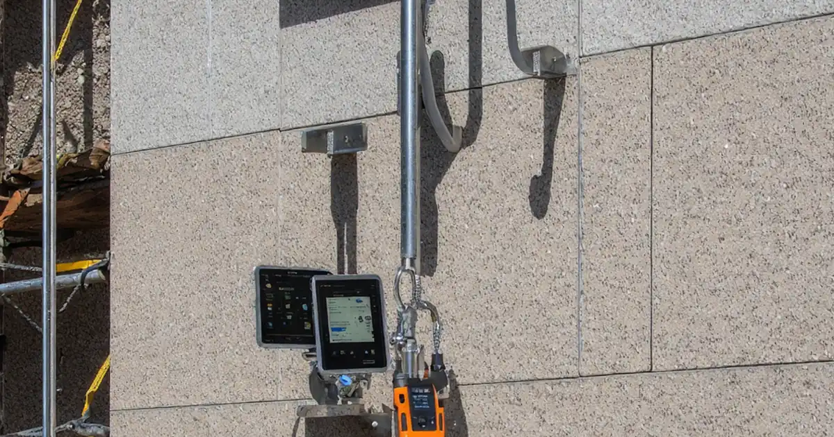
Install shear keys/dowels at pile heads is a focused installation and QA process for transferring shear across the pile-to-cap interface. This checklist covers drilled dowel installation, epoxy anchoring, and embedment verification while explicitly excluding reinforcement starters. It guides site engineers and inspectors through layout, rebar scanning, drilling, hole cleaning, adhesive injection, bar alignment, and post-cure checks. By standardizing dowel installation at pile heads, teams reduce risks like striking reinforcement, voided adhesive bonds, inadequate embedment, misalignment, and early loading before full cure. The result is reliable shear transfer and orderly records ready for quality and compliance reviews. Practical cues—such as angle tolerances, brush–blow cycles, moisture control, and proof testing if specified—are paired with photo evidence, batch tracking, and signatures. Use this interactive checklist to tick each step, comment on anomalies, attach photos and reports, and export your completed records to PDF/Excel with a secure QR link.
- A disciplined method for drilling, epoxy anchoring, and aligning dowels at pile heads that avoids reinforcement strikes, prevents voids and under-embedment, and documents temperatures, batch numbers, and approvals for robust shear transfer performance.
- Field-proven sequence with acceptance tolerances for angle, spacing, hole preparation, and cured embedment. Includes hold points, optional proof pull testing, and clear evidence requirements—photos, measurements, and signatures—to streamline quality assurance and audits.
- Interactive online checklist with tick, comment, and export features secured by QR code. Capture bore photos, adhesive lot numbers, and alignment readings, then export to PDF/Excel for distribution to contractors, consultants, and authorities.
- Scope stays specific to shear keys/dowels at pile heads and excludes reinforcement starters. The checklist supports compliant installation per approved project specifications and authority requirements without prescribing project-specific design clauses.
Pre-Installation Verification
Drilling and Hole Preparation
Bar Preparation and Epoxy Grout
Installation and Alignment
Embedment Verification and QA
Finishing and Documentation
Scope, boundaries, and intent
This checklist controls the installation of shear keys/dowels at pile heads to provide reliable shear transfer into the pile cap. It explicitly excludes reinforcement starters; only drilled dowels bonded with epoxy/grout are within scope. The process emphasizes coordinated setout, reinforcement scanning, controlled drilling, hole cleaning, adhesive handling, bar insertion, and alignment holding until full cure. By focusing on bond quality and embedment confirmation, it avoids common failures such as dust-contaminated holes, rebar strikes, under-embedment, and premature loading. Acceptance cues are practical: angle and spacing tolerances, brush–blow cycles, depth measurements, temperature logs, and photographic evidence. The outcome is a verifiable installation trail suitable for engineer review and regulatory audits. Use it for new works, remediation, or interface detailing where dowelled shear transfer is specified, always aligning details with approved drawings and manufacturer technical data sheets.
- Scope: pile head dowels only, exclude reinforcement starters.
- Use ferroscan/GPR to avoid hitting existing reinforcement.
- Maintain angle ≤ 2° and setout tolerance ±5 mm.
- Record temperatures, batch numbers, and cure times.
- Capture scaled photos before and after insertion.
Drilling, cleaning, and adhesive bonding essentials
Bond quality depends on precise drilling and immaculate hole preparation. A stable drill stand and digital angle gauge hold orientation; a calibrated depth rod confirms embedment within ±5 mm. Near edges, moderate percussion to minimize spalls and maintain required distances. Clean each hole with nylon brush and oil-free compressed air in repeated brush–blow cycles until dust-free. Control moisture to the adhesive’s requirements—dry or SSD—documented with swab checks. Prepare bars by abrading to bright metal, degreasing, and marking the insertion line. Condition cartridges, fit a new nozzle, and purge until colour is uniform. Inject adhesive from the hole bottom, withdrawing the nozzle to eliminate voids, then rotate the bar during insertion to wet all surfaces. Hold alignment with jigs through gel time, prevent disturbance, and tidy expelled adhesive into a neat fillet.
- Stable jig; verify angle with digital gauge.
- Depth within ±5 mm using a calibrated rod.
- Brush–blow cycles until holes are dust-free.
- Control moisture per adhesive TDS requirements.
- Purge nozzle; inject from hole bottom upward.
Verification, tolerances, and evidence-driven QA
Quality assurance pairs measurable tolerances with clear evidence. Verify setout (±5 mm), angle (≤ 2°), and projection against bar markings. Log ambient and substrate temperatures influencing cure; respect gel and full-cure times before any load or impact. After curing, confirm embedment by probe or endoscope where accessible. Where specified, execute proof pull tests with a calibrated rig and retain the calibration certificate. Every hole should carry traceable records: adhesive batch and expiry, purge length, insertion time, photos of bore cleaning, filled hole, depth mark alignment, and finished annulus. Capture approvals at ITP hold points and clearly state that reinforcement starters are excluded. Package all evidence into an exportable report for the engineer, client, and authority reviewers.
- Angle ≤ 2°; spacing tolerance ±5 mm.
- Cure per TDS before load or vibration.
- Probe/embedment verification with photos or video.
- Proof pull testing if project specifications require.
- Export QA pack with batches, photos, signatures.
How to use this interactive checklist for dowel installation
- Preparation: Brief the team on scope (exclude starters). Assemble drill stand, rotary/diamond drill, nylon brushes, oil-free air, ferroscan, depth rod, infrared thermometer, adhesive system with nozzles, jigs, PPE, and forms. Confirm drawings, ITP, and TDS.
- Project setup: Enter project, pile IDs, dowel sizes, design embedment, and hold points. Preload acceptance tolerances (±5 mm, ≤ 2°) and required evidence (photos, batch numbers, signatures).
- Using the Interactive Checklist: Start interactive mode, tick steps as completed, add comments for deviations, attach photos/scans, and tag responsible parties. Generate interim exports to PDF/Excel for daily reviews.
- Sign-Off and Archiving: Capture digital signatures from installer, supervisor, and engineer. Lock the record with a QR-secured link, distribute to stakeholders, and archive with attachments for audits.

Call to Action
- Start Checklist Tick off tasks, leave comments on items or the whole form, and export your completed report to PDF or Excel—with a built-in QR code for authenticity.
- Download Excel - Pile Head Shear Key/Dowel Installation
- Download PDF - Pile Head Shear Key/Dowel Installation
- View Image - Pile Head Shear Key/Dowel Installation
Cite & Embed
“Pile Head Shear Key/Dowel Installation by Quollnet”
with a link to
this source page.
FAQ
Question: What embedment depth should I use for dowels at pile heads?
Question: Can I install epoxy dowels if the holes are damp or the weather is cold?
Question: How do I avoid striking existing reinforcement while drilling pile heads?
Question: When is it safe to load or pour the pile cap after installing dowels?
Question: Are proof pull-out tests required for these dowels?
Related Articles
Broader reading and guidance connected to this checklist topic.


Improve Your Project Handover Process With Snag List Tracking App


Open Ncrs At Taking-over / Dlp: What Happens At Handover And How To Escalate
Related Checklists
Keep the workflow moving with nearby templates chosen from similar checklist content.