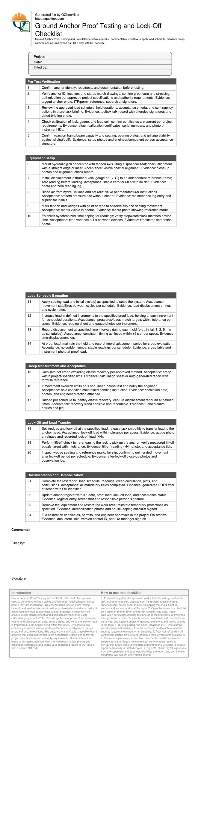
Ground Anchor Proof Testing and Lock-Off Checklist
Definition: Ground Anchor Proof Testing and Lock-Off guides QA teams to apply the approved load schedule, measure movement and creep, and verify lock-off load transfer without covering anchor installation activities.
- Apply calibrated load schedule and record displacement at defined intervals.
- Validate capacity, stiffness, and load transfer before structural reliance.
- Capture readings, photos, signatures, and approvals per project specifications.
- Interactive, commentable checklist with export and QR code verification.
Ground Anchor Proof Testing and Lock-Off is the controlled process used to demonstrate that installed anchors meet required performance before they are relied upon. This checklist focuses on proof testing, lock-off, and load transfer confirmation, and excludes installation tasks. It aligns with common geotechnical anchor practices, including lift-off checks, creep measurement, and displacement monitoring using calibrated gauges or LVDTs. You will apply the approved load schedule, record time-displacement data, assess creep, and verify the lock-off load is transferred to the anchor head within tolerance. By following this process, you reduce risks of underperformance, misalignment, gauge error, and unsafe reactions. The outcome is a verifiable, traceable record showing that each anchor meets the acceptance criteria per approved project specifications and authority requirements. Start in interactive mode to tick items, add comments for variances, attach photos and calibration certificates, and export your completed record to PDF/Excel with a secure QR code.
- Use this checklist to execute the approved proof load schedule with calibrated equipment, capture time-displacement readings, evaluate creep, and document lock-off load transfer. It supports transparent QA and timely engineer acceptance for each tested anchor.
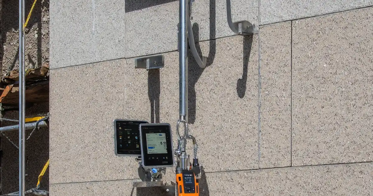
- Practical instructions help you align the jack, verify reaction adequacy, zero displacement instruments to an independent datum, and maintain consistent timing at each hold. The workflow reduces errors linked to gauge drift, air in lines, and unstable references.
- Interactive online checklist with tick, comment, and export features secured by QR code.
- Complete documentation is built-in: anchor ID, calibration certificates, photos of setup, load and movement logs, creep plots, lock-off results, and signatures. Export standardized reports to accelerate approvals and maintain a defensible audit trail.
Pre-Test Verification
Equipment Setup
Load Schedule Execution
Creep Measurement and Acceptance
Lock-Off and Load Transfer
Documentation and Demobilization
Plan the Proof Test for Reliable, Defensible Results
A successful ground anchor proof test starts with disciplined planning. Confirm the approved load schedule, acceptance criteria, and reporting format so the crew knows exactly what to capture. Use calibrated hydraulic jacks, pressure gauges, or load cells to read force in kN, and set up an independent reference frame for displacement using a dial gauge or LVDT. Concentric alignment through a spherical seat minimizes parasitic bending that distorts readings. Reaction beams or frames must be rated and properly seated on bearing plates to avoid settlement during holds. Establish synchronized timing for all observations; consistent intervals make creep assessments credible. Finally, hold a short briefing, show the anchor ID and test limits, and agree the escalation path if creep or slip exceeds limits. Planning protects safety and quality while reducing rework, schedule slips, and disputes with stakeholders.
- Confirm load schedule, acceptance, and reporting format upfront.
- Use calibrated force measurement; record serials and certificates.
- Zero displacement gauges to an independent, rigid frame.
- Maintain concentric alignment to limit bending effects.
- Brief the team and define escalation for exceedances.
Execute the Load Schedule and Measure Creep Consistently
During execution, increase load in defined increments, holding at each stage for the specified duration. At each hold, record displacement at consistent time stamps to develop a clear time–movement curve. At proof load, maintain the hold and continue timed readings for creep evaluation; calculate net creep in accordance with the approved method so elastic recovery is not double-counted. Watch for non-linear movements, step changes, or unstable gauge behavior; these can indicate seating, grout defects, or reaction movement. When unloading, capture rebound to verify elastic behavior and to support stiffness calculations. Accurate, consistent timing across all anchors improves comparability and speeds acceptance decisions by the engineer.
- Hold at each increment per the approved schedule.
- Record displacement at consistent, predefined time stamps.
- Calculate net creep using the approved method.
- Investigate non-linear or step changes in movement.
- Document rebound during unloading for stiffness checks.
Lock-Off, Verify Load Transfer, and Close Out Documentation
After acceptance at proof load, set the wedges and transfer load to the anchor head at the specified lock-off value. Confirm the transfer using a lift-off check: re-engage the jack and verify the measured lift-off matches the target within the tolerance in the project specifications. Inspect reference marks for slip and ensure the head remains stable for the observation period. Then finalize reporting: attach calibration certificates, photos of alignment and gauges, time–displacement tables, creep calculations, and plots. Update the anchor register with proof load, lock-off load, and acceptance status. Collect digital signatures from the site supervisor and engineer to close the test and archive records in the QA system.
- Set wedges and release to specified lock-off load.
- Verify load transfer with a documented lift-off check.
- Check reference marks to rule out unintended slip.
- Compile plots, certificates, and signatures in one report.
- Update the register and archive with version control.
How to Use This Ground Anchor Proof Testing Checklist
- Preparation: gather the approved load schedule, test rig, calibrated jack, gauge or load cell, displacement instrument, reaction frame, spherical seat, safety gear, and housekeeping materials. Confirm permits and access, and brief the team.
- Open the interactive checklist on a tablet or phone. Enter anchor ID, location, and date. Attach calibration certificates and pre-test photos to the first items.
- Progress through items in order. Tick each step as completed, add comments for variances, and capture photos of gauges, alignment, and marks directly in the form.
- During loading and holds, input load (kN), time stamps, and displacement readings. Use the comment field to note anomalies such as reaction movement or air bleeding.
- After lock-off and lift-off verification, upload plots or auto-generate them if your system supports it. Review completeness; unresolved comments must be addressed before sign-off.
- Export the completed, commentable record to PDF/Excel. Share with stakeholders and embed the QR code to secure report authenticity in printed copies.
- Sign-Off: obtain digital signatures from the supervisor and engineer, distribute the report, and archive it in the project QA system with version control.
Call to Action
- Start Checklist Tick off tasks, leave comments on items or the whole form, and export your completed report to PDF or Excel—with a built-in QR code for authenticity.
- Download Excel - Ground Anchor Proof Testing and Lock-Off
- Download PDF - Ground Anchor Proof Testing and Lock-Off
- View Image - Ground Anchor Proof Testing and Lock-Off
Cite & Embed
“Ground Anchor Proof Testing and Lock-Off by Quollnet”
with a link to
this source page.

FAQ
Question: What is the difference between a proof test and a performance test for ground anchors?
Question: How should creep be measured and evaluated during proof load holds?
Question: What actions should I take if movement exceeds limits at proof load?
Question: How do I verify that the lock-off load has been correctly transferred to the anchor?
Question: Which records are mandatory to attach to the proof test report?
Related Articles
Broader reading and guidance connected to this checklist topic.


Is It Important To Customize Your Qr Code And How To Do It?


Master Construction Project Cashflow With Cashflowpot

Related Checklists
Keep the workflow moving with nearby templates chosen from similar checklist content.