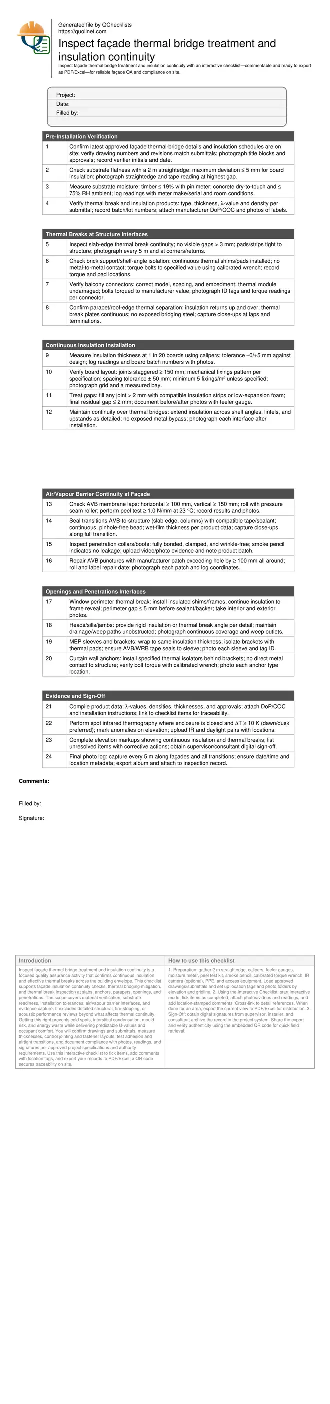
Inspect façade thermal bridge treatment and insulation continuity
Definition: Inspect façade thermal bridge treatment and insulation continuity guides site teams in verifying continuous insulation, thermal breaks, and airtight transitions across façades to minimise heat loss and condensation risks.
- Verify thermal breaks, continuous insulation, and airtight interface treatments.
- Reduce thermal bridging, surface condensation, and long-term energy penalties.
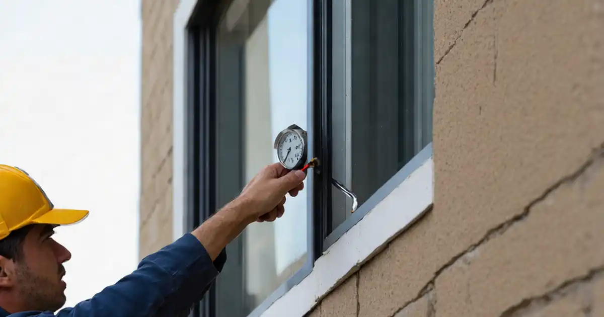
- Use gauges, torque tools, adhesion tests, photos, and IR scans.
- Tick, comment, export to PDF/Excel; QR code-secured records.
Inspect façade thermal bridge treatment and insulation continuity is a focused quality assurance activity that confirms continuous insulation and effective thermal breaks across the building envelope. This checklist supports façade insulation continuity checks, thermal bridging mitigation, and thermal break inspection at slabs, anchors, parapets, openings, and penetrations. The scope covers material verification, substrate readiness, installation tolerances, air/vapour barrier interfaces, and evidence capture. It excludes detailed structural, fire-stopping, or acoustic performance reviews beyond what affects thermal continuity. Getting this right prevents cold spots, interstitial condensation, mould risk, and energy waste while delivering predictable U-values and occupant comfort. You will confirm drawings and submittals, measure thicknesses, control jointing and fastener layouts, test adhesion and airtight transitions, and document compliance with photos, readings, and signatures per approved project specifications and authority requirements. Use this interactive checklist to tick items, add comments with location tags, and export your records to PDF/Excel; a QR code secures traceability on site.
- This checklist drives envelope performance by confirming continuous insulation, correct thermal break installation, and airtight transitions at typical façade interfaces. It reduces heat loss, surface condensation, and rework by defining practical methods, measurable tolerances, and clear acceptance evidence suitable for construction-stage verification.
- Field-ready steps pair tools with outcomes: straightedge flatness checks, feeler-gauge gap limits, membrane lap and peel strengths, torque-verified anchors, and targeted thermography. Each instruction specifies acceptance criteria and required evidence—photos, readings, batch data, and sign-offs—so findings withstand design, contractor, and client review.
- Interactive online checklist with tick, comment, and export features secured by QR code.
- Integrated documentation links approved details, product data, and location-based photos to each task. This creates a traceable audit trail for compliance, supports handover, and enables early detection of discontinuities at slab edges, shelf angles, window perimeters, parapets, and MEP sleeves before finishes conceal defects.
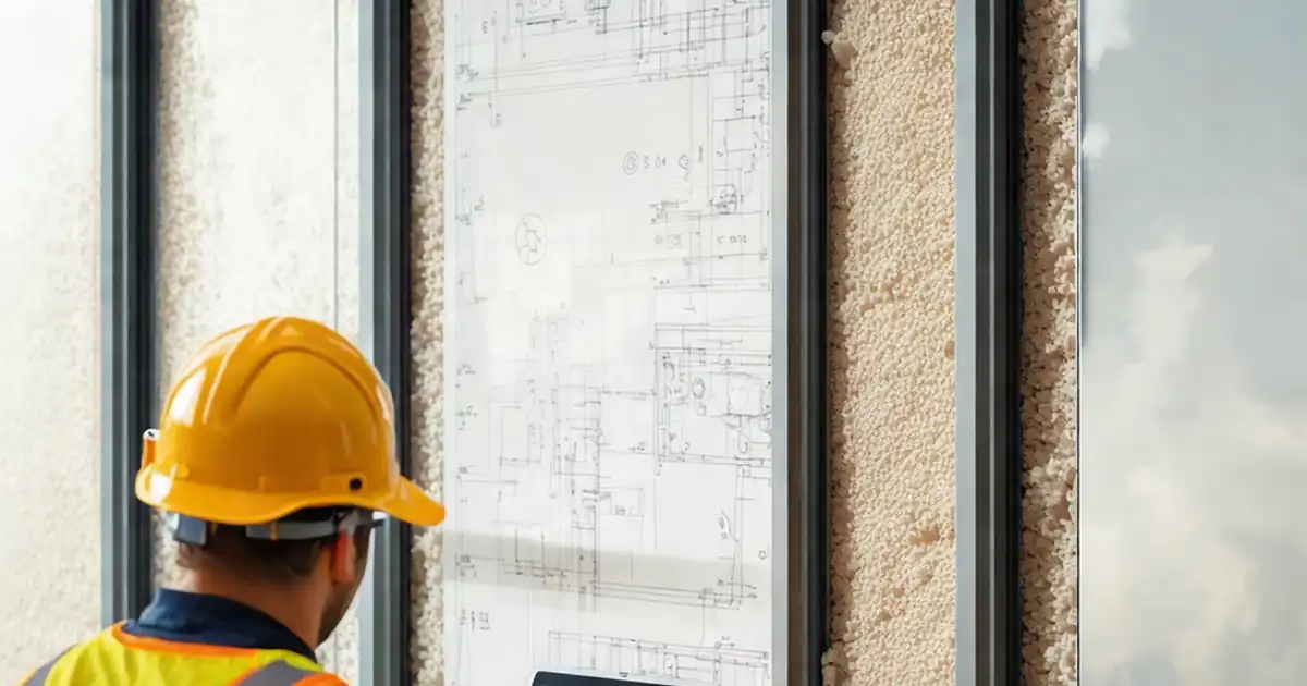
Pre-Installation Verification
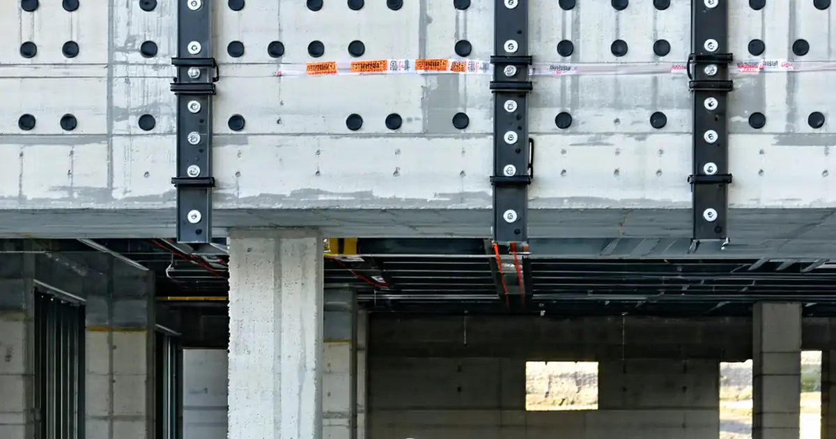
Thermal Breaks at Structure Interfaces
Continuous Insulation Installation
Air/Vapour Barrier Continuity at Façade
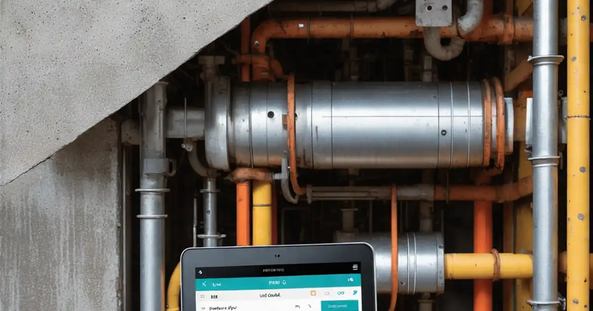
Openings and Penetrations Interfaces
Evidence and Sign-Off
Why thermal bridges matter and how continuity prevents failures
Thermal bridges occur where conductive materials bypass insulation at slabs, anchors, parapets, and openings. Even small gaps or uninsulated brackets can create cold surfaces that promote condensation, mould growth, and occupant discomfort while eroding calculated U-values. Continuity relies on three fundamentals: maintain unbroken insulation thickness, insert tested thermal breaks wherever metal crosses the envelope, and ensure the air/vapour barrier transitions are airtight so convective heat loss cannot short-circuit performance. Acceptance cues are visual and measurable: slab-edge isolators without gaps greater than 3 mm, insulation boards at the designed thickness with staggered joints, and AVB laps of at least 100–150 mm verified with peel tests. Real projects show that the highest risk points are shelf angles, balcony connectors, and window perimeters—interfaces that benefit from pre-cut shims, clear torque values, and fit-for-purpose sealants. By inspecting during installation, you avoid inaccessible defects later and lock in predictable energy performance.
- Continuity equals thickness, thermal breaks, and airtight transitions.
- Target maximum insulation gaps of 2 mm after treatment.
- Set AVB lap/peel values and verify on site.
- Focus on slab edges, anchors, and openings.
- Inspect before finishes conceal interfaces.
Practical inspection methods, tolerances, and evidence capture
An efficient sequence starts with documents and substrates: confirm latest details, product approvals, and substrate flatness (≤ 5 mm over 2 m). Check moisture (timber ≤ 19%) before tapes or insulation. During installation, sample insulation thickness with calipers (−0/+5 mm), control joint staggering (≥ 150 mm), and verify fixing density and spacing (tolerance ± 50 mm). For AVB, roll laps and perform peel tests (≥ 1.0 N/mm at 23 °C). At penetrations, use smoke pencils for local leakage checks. For anchors and balcony connectors, use calibrated torque wrenches and document readings. Where enclosures allow, supplemental infrared scans at dawn/dusk with a temperature differential of at least 10 K help flag discontinuities; always pair thermal images with daylight photos and marked elevations. Each step should end with evidence: photos, meter readings, batch labels, and digital signatures—linked to location so findings withstand audits per approved project specifications and authority requirements.
- Measure, don’t guess: use gauges, meters, and torque tools.
- Sample frequently: 1 in 20 boards minimum thickness checks.
- Record peel and torque values with photos.
- Pair IR images with daylight context and locations.
- Link evidence to drawings for traceability.
Common failure points and robust corrective actions
Frequent issues include missing shims at shelf angles, misaligned balcony connectors, and insulation joints left open. Correct by inserting the specified thermal isolators, re-torquing anchors, and packing joints with compatible insulation or low-expansion foam to leave residual gaps ≤ 2 mm. At window perimeters, extend insulation into reveals and use insulated shims under frames so backer rod and sealant are not the only barriers. Slab edges often show exposed steel; wrap with rigid boards and seal AVB transitions to prevent air leakage at the floor line. If AVB adhesion is marginal, clean substrates, apply primers, and re-test peel strength before covering. After any fix, repeat the original test—re-measure thickness, re-check torque, or re-scan thermally—to confirm resolution. Document the before/after condition with photos and update the elevation markup so future teams can rely on a clear, verified record.
- Pack and seal joints to ≤ 2 mm residual gaps.
- Install isolators at all anchors and verify torque.
- Extend insulation into window reveals.
- Re-test after any corrective work.
- Update drawings with resolved discrepancies.
How to Use This Interactive Inspection Checklist
- Preparation: gather 2 m straightedge, calipers, feeler gauges, moisture meter, peel test kit, smoke pencil, calibrated torque wrench, IR camera (optional), PPE, and access equipment. Load approved drawings/submittals and set up location tags and photo folders by elevation and gridline.
- Using the Interactive Checklist: start interactive mode, tick items as completed, attach photos/videos and readings, and add location-stamped comments. Cross-link to detail references. When done for an area, export the current view to PDF/Excel for distribution.
- Sign-Off: obtain digital signatures from supervisor, installer, and consultant; archive the record in the project system. Share the export and verify authenticity using the embedded QR code for quick field retrieval.
Call to Action
- Start Checklist Tick off tasks, leave comments on items or the whole form, and export your completed report to PDF or Excel—with a built-in QR code for authenticity.
- Download Excel - Façade Thermal Bridge and Insulation Continuity Inspection
- Download PDF - Façade Thermal Bridge and Insulation Continuity Inspection
- View Image - Façade Thermal Bridge and Insulation Continuity Inspection
Cite & Embed
“Façade Thermal Bridge and Insulation Continuity Inspection by Quollnet”
with a link to
this source page.
FAQ
Question: When should façade thermal bridge and insulation continuity inspections occur?
Question: What gap or tolerance is acceptable between insulation boards?
Question: How can I verify airtight AVB transitions without a full blower door test?
Question: Are infrared scans mandatory to find thermal bridges during construction?
Question: What documentation is needed for compliance and handover?
Related Articles
Broader reading and guidance connected to this checklist topic.


Advanced High-rise Fire Safety: Drones & Modern Equipment


Is It Important To Customize Your Qr Code And How To Do It?
Related Checklists
Keep the workflow moving with nearby templates chosen from similar checklist content.