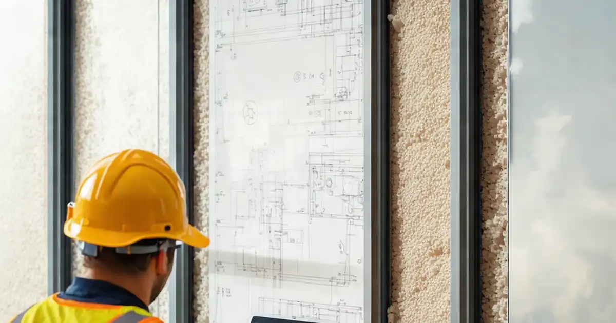
Inspect curtain wall insulation continuity behind spandrel areas
Definition: Inspect curtain wall insulation continuity behind spandrel areas for thermal performance, moisture control, and build quality, guiding site inspectors, facade specialists, and contractors through clear acceptance cues and evidence capture.
- Verify continuous thermal insulation and air/vapour control behind spandrels
- Reduce thermal bridging, condensation risk, and cold-strip occupant complaints
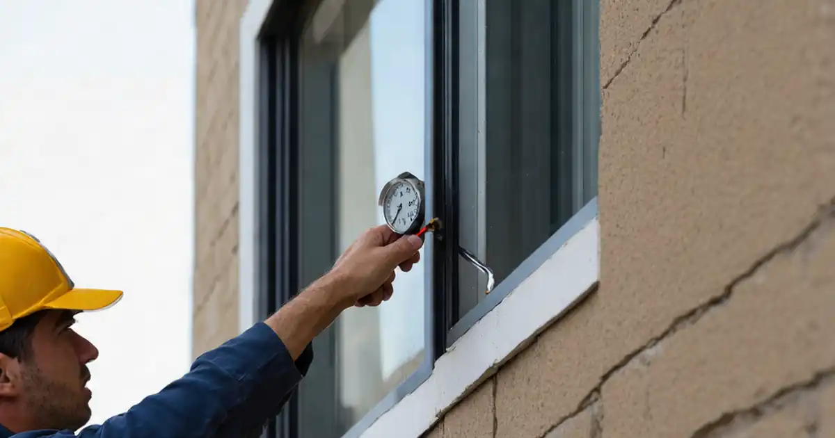
- Use thickness gauges, borescopes, IR thermography, and documented tolerances
- Interactive, commentable checklist with export and QR code authentication
Inspect curtain wall insulation continuity behind spandrel areas to ensure the opaque zones deliver intended thermal performance without hidden gaps. This checklist focuses on spandrel back-pan insulation, thermal break continuity, and air/vapour barrier interfaces within unitized or stick-built curtain walls. It excludes vision glass performance, structural glazing, and code-specific firestopping details, but pays close attention to transitions, penetrations, and bracket interfaces where thermal bridging and condensation often originate. By verifying insulation thickness, joint treatment, adhesive coverage, and sealed back-pan seams, you reduce cold-strip complaints, dew point formation, and moisture damage to finishes. Methods include pin depth gauges, straightedges, calibrated thermometers, borescopes, and IR thermography under controlled temperature differentials. Acceptance cues are practical and measurable so teams can resolve nonconformances early, preventing rework and costly access later. Use this interactive, field-friendly tool to tick findings, add comments, attach photos, and export to PDF or Excel with a QR code for authenticated records.
- Ensure opaque spandrel zones align with the thermal plane by confirming insulation thickness, tight joints, sealed back-pans, and air/vapour barrier overlaps. Measurable tolerances and photo evidence reduce risk of thermal bridges and interior condensation at slab edges, anchors, and perimeter conditions.
- Integrate inspection timing with fabrication deliveries and facade drops to catch defects before glazing-in. Verifying adhesive coverage, mechanical fixing patterns, and transition detailing limits rework, preserves programme dates, and supports reliable in-service U-values and occupant comfort in perimeter zones.
- Interactive online checklist with tick, comment, and export features secured by QR code.
- Document materials by lot number and location, capture borescope and IR images, and archive approvals. Clear acceptance criteria enable swift closeout, transparent accountability across trades, and confident sign-off per approved project specifications and authority requirements.
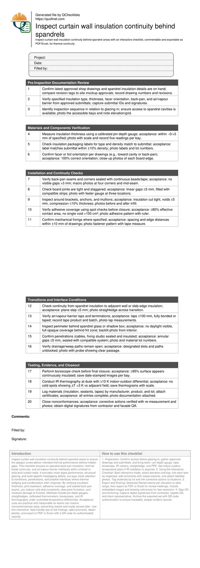
Pre-Inspection Documentation Review
Materials and Components Verification
Installation and Continuity Checks
Transitions and Interface Conditions
Testing, Evidence, and Closeout
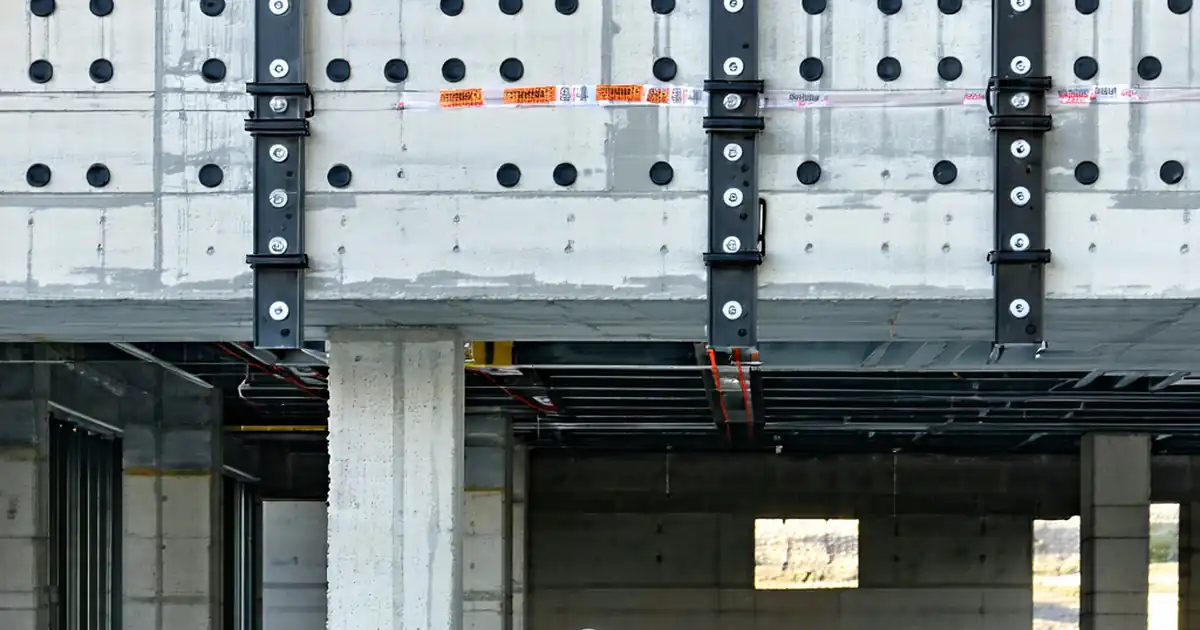
Why spandrel insulation continuity matters
Opaque spandrel zones hide the most common façade thermal bridges: gaps at back-pans, misaligned boards, crushed insulation at brackets, and broken air/vapour barriers. When continuity breaks, interior finishes experience cold strips, condensation, mould risk, and occupant discomfort. This checklist targets the spandrel cavity only, from back-pan and insulation to immediate interfaces with mullions, brackets, and adjacent insulated assemblies. It excludes vision glazing performance and code-specific firestopping, though it verifies that insulation does not obstruct designed drainage or weeps. Acceptance cues remain measurable: thickness within tolerance, joint gaps limited and backfilled, sealed seams, and consistent alignment with the thermal plane. Field teams capture labelled photos, borescope views, and IR images to prove coverage. By inspecting before glazing-in and again at representative completed bays, you reduce rework, protect programme, and achieve predictable façade U-values and interior comfort near slab edges.
- Focus on opaque spandrel cavities only
- Prevent thermal bridges and condensation bands
- Use measurable, repeatable acceptance cues
- Capture photo and IR evidence per bay
- Inspect before glazing-in where possible
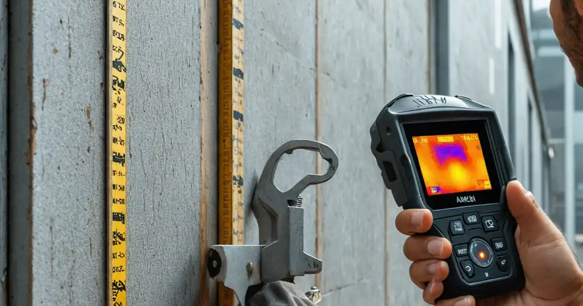
Practical acceptance targets and field methods
On site, start by confirming approved details and submittals match delivered materials. Measure insulation thickness with a calibrated pin gauge and verify density from packaging. Board joints must be tight and staggered; any linear gaps over 5 mm are backfilled with compatible mineral wool strips. Back-pan seams and corners get continuous beads or tapes without voids. Adhesive coverage should reach at least 80% effective contact, with no single void exceeding 100 cm²; mechanical fasteners follow drawing spacing within ±10 mm. Maintain the thermal plane across transitions with steps no greater than 5 mm. At penetrations and brackets, cut insulation tight, keeping compression below 10% of thickness. Seal air/vapour barrier laps with minimum 100 mm overlaps. Before closure, perform borescope checks; after representative completion, run IR scans at dusk with at least a 10 K differential, flagging any cold spots above 3 K variance.
- Thickness within −0/+5 mm of specified
- Joint gaps ≤5 mm, backfilled where needed
- Adhesive coverage ≥80% effective contact
- Fixing spacing within ±10 mm of drawings
- IR cold spots limited to ΔT ≤3 K
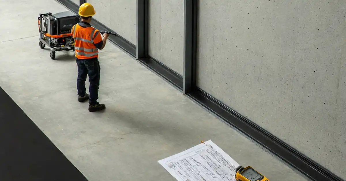
Documentation, timing, and closeout confidence
Synchronize inspections with unit deliveries and installation drops to ensure cavities remain accessible prior to glazing-in. Record gridlines, elevations, bay numbers, and orientation to make findings repeatable. For each bay, compile submittal references, lot numbers, and acceptance photos. Backlit interior photos help prove opacity behind frit zones, while borescopes confirm coverage where access is tight. IR thermography validates thermal continuity after larger areas are enclosed, provided a minimum 10 K delta exists. Nonconformances should include location-tagged photos, a measured deviation, the proposed fix, and re-inspection evidence. Final closeout bundles drawings, approvals, field records, and signatures. Using exportable reports reinforces traceability and simplifies turnover to commissioning and operations teams. All acceptance remains per approved project specifications and authority requirements.
- Inspect early, then sample after enclosure
- Tag every finding to grid and elevation
- Use borescopes and backlit photos
- Archive IR scans with scale and notes
- Bundle approvals and digital signatures
How to use this interactive checklist
- Preparation: Confirm access before glazing-in, gather approved drawings and submittals, and bring tools—pin depth gauge, tape, borescope, IR camera, straightedge, and PPE. Set indoor-outdoor temperature plans if IR validation is required.
- Using the Interactive Checklist: Start interactive mode, select elevation and bay, tick each item as inspected, add comments with measurements, and attach labelled photos. Tag materials by lot and link corrective actions to locations.
- Export and Sharing: Generate filtered reports per elevation or date range, then export as PDF or Excel for review meetings. Include embedded images and drawing references for fast resolution.
- Sign-Off and Archiving: Capture digital signatures from contractor, façade QA, and client representative. Archive the exported set with QR code authentication to ensure traceable, tamper-evident records.
Call to Action
- Start Checklist Tick off tasks, leave comments on items or the whole form, and export your completed report to PDF or Excel—with a built-in QR code for authenticity.
- Download Excel - Curtain Wall Spandrel Insulation Continuity Inspection
- Download PDF - Curtain Wall Spandrel Insulation Continuity Inspection
- View Image - Curtain Wall Spandrel Insulation Continuity Inspection
Cite & Embed
“Curtain Wall Spandrel Insulation Continuity Inspection by Quollnet”
with a link to
this source page.

FAQ
Question: When should I inspect spandrel insulation continuity during installation?
Question: What tools provide the most reliable evidence for hidden spandrel areas?
Question: How tight should insulation joints be behind spandrel glass?
Question: Can IR thermography replace physical inspection in spandrel zones?
Related Articles
Broader reading and guidance connected to this checklist topic.


Is It Important To Customize Your Qr Code And How To Do It?
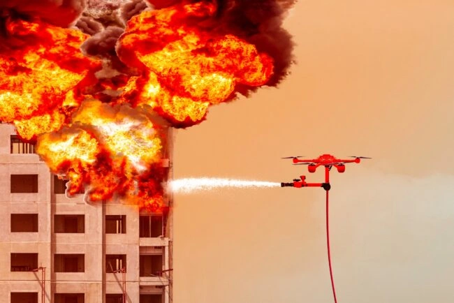
Advanced High-rise Fire Safety: Drones & Modern Equipment
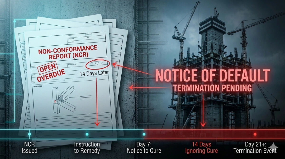
Can An Ncr Lead To Termination? Hidden Risk Behind “notice To Correct”
Handmade Ceramics And Technique
Related Checklists
Keep the workflow moving with nearby templates chosen from similar checklist content.