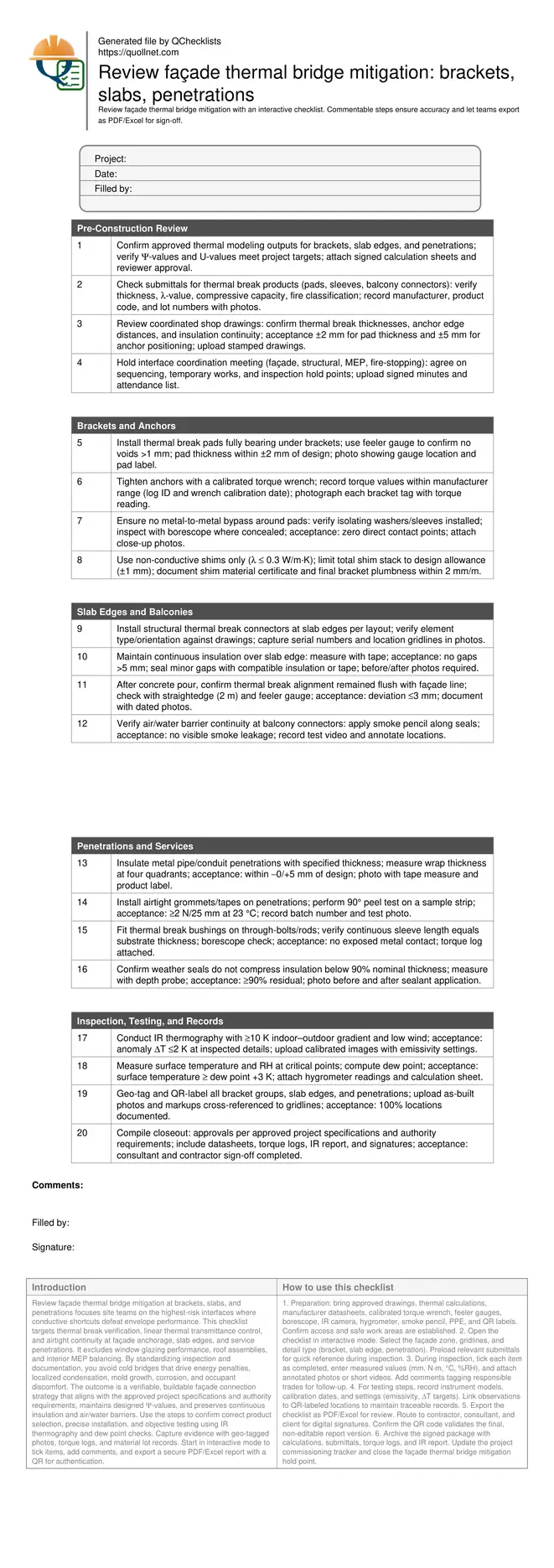
Façade Thermal Bridge Mitigation Review: Brackets, Slabs, Penetrations
Definition: Review façade thermal bridge mitigation at brackets, slabs, and penetrations is a field-ready checklist for envelope engineers and supervisors confirming thermal breaks, continuity, and airtightness to minimize heat loss and condensation.
- Target brackets, slab edges, and service penetrations with measurable criteria.
- Reduce heat loss, cold spots, and mold by verifying thermal breaks.
- Apply practical tools: torque wrenches, feeler gauges, IR cameras, hygrometers.
- Interactive, commentable checklist; export reports and verify via QR code.
Review façade thermal bridge mitigation at brackets, slabs, and penetrations focuses site teams on the highest-risk interfaces where conductive shortcuts defeat envelope performance. This checklist targets thermal break verification, linear thermal transmittance control, and airtight continuity at façade anchorage, slab edges, and service penetrations. It excludes window glazing performance, roof assemblies, and interior MEP balancing. By standardizing inspection and documentation, you avoid cold bridges that drive energy penalties, localized condensation, mold growth, corrosion, and occupant discomfort. The outcome is a verifiable, buildable façade connection strategy that aligns with the approved project specifications and authority requirements, maintains designed Ψ-values, and preserves continuous insulation and air/water barriers. Use the steps to confirm correct product selection, precise installation, and objective testing using IR thermography and dew point checks. Capture evidence with geo-tagged photos, torque logs, and material lot records. Start in interactive mode to tick items, add comments, and export a secure PDF/Excel report with a QR for authentication.
- Focuses inspections on façade brackets, slab edges, and service penetrations, where most conductive paths occur. Verifies documented Ψ-values, correct thermal break products, and dimensional tolerances, preventing costly rework and ensuring consistent energy, comfort, and moisture outcomes across typical high-rise cladding interfaces.
- Provides stepwise acceptance criteria using SI units and job-ready tools: calibrated torque wrenches, feeler gauges, borescopes, IR cameras, and hygrometers. Each item specifies what to measure, acceptable ranges, and the evidence to collect for clear, defensible closeout records.
- Links thermal breaks with continuous insulation and airtight layers, ensuring no metal-to-metal bypasses, crushed insulation, or displaced connectors. Includes guidance on balcony connectors and grommeted penetrations to maintain continuity through structural elements without compromising safety or serviceability.
- Interactive online checklist with tick, comment, and export features secured by QR code. Teams collaborate in real time, attach annotated photos and logs, and produce a standardized PDF/Excel handover package aligned with approved project specifications and authority requirements.
Pre-Construction Review
Brackets and Anchors
Slab Edges and Balconies
Penetrations and Services
Inspection, Testing, and Records
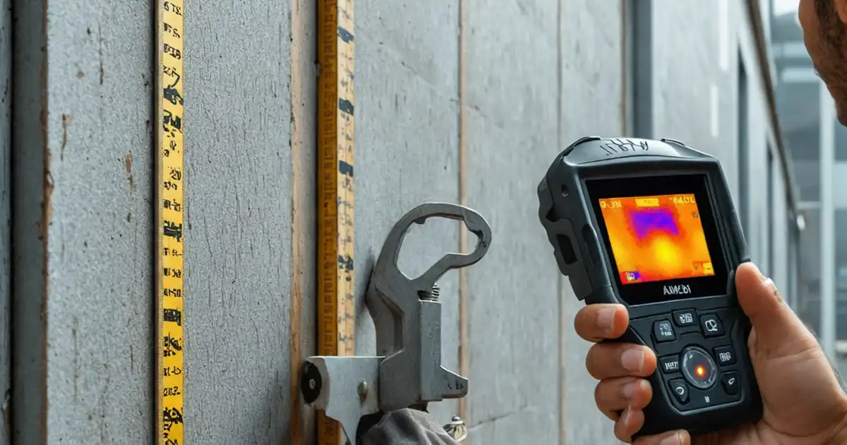
Why bracket interfaces dominate façade thermal bridging
Bracket-to-structure connections are frequent, load-bearing, and often the shortest conductive paths, making them prime thermal bridge hotspots. Effective mitigation relies on verified thermal break pads, correct anchor detailing, and strict control of unintended metal-to-metal contacts. Field teams should prioritize bearing area coverage and torque control, since over-tightening can crush pads, reducing effective thickness and increasing conductivity. Non-conductive shims help accommodate plumbness without creating new bridges, but only when their λ-values and stack heights remain within design limits. Use borescopes to inspect hidden areas and capture close-up photos of pad markings and washers. Acceptance cues include full pad contact (no gaps exceeding 1 mm), anchors torqued within manufacturer limits, and documented shim materials. Jobsite examples show that replacing a single steel shim stack with glass-fibre reinforced polymer shims restored modeled Ψ-values and removed an IR-visible cold spot at a windy corner bay during commissioning.
- Cover entire bracket footprint with continuous thermal pad.
- Torque anchors to manufacturer limits with calibrated tools.
- Eliminate unintended metal-to-metal bypasses at interfaces.
- Use low-λ shims within allowed stack thickness.
- Document pad labels, lot numbers, and torque logs.
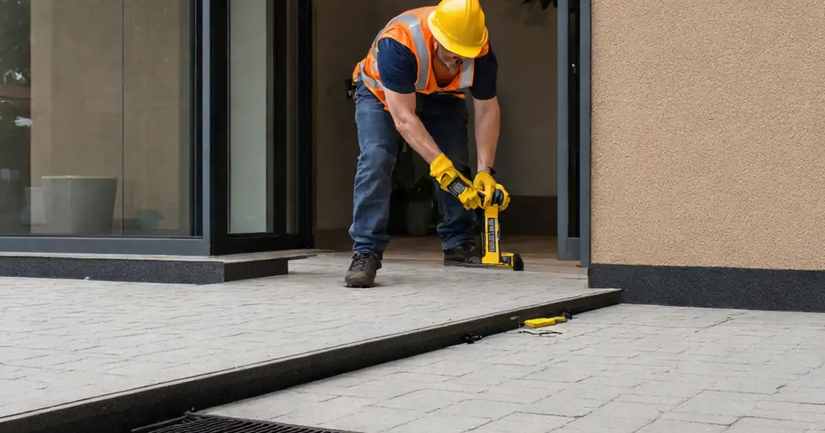
Maintaining continuity at slab edges and balconies
Slab edges interrupt insulation lines and often carry balcony loads, so thermal breaks must be structural and continuous. Verify connector type and orientation before pour, then re-check alignment afterwards with straightedges to confirm tolerances. Adjacent insulation should bridge over connectors without gaps or compression that reduces performance. Air and water barriers must tie into connector zones using compatible primers and tapes to maintain airtight continuity. Field smoke tests quickly reveal leaks at transitions, while photos of serial numbers and gridline references streamline later audits. Acceptance cues include correct connector orientation, insulation gaps under 5 mm, and post-pour deviations no more than 3 mm. A practical example: a mis-rotated balcony connector shifted the thermal element outside the insulation plane; catching it at a hold point avoided chiseling hardened concrete and preserved the designed linear transmittance.
- Verify connector orientation and type before concrete pour.
- Insulation continuity with no gaps over 5 mm.
- Post-pour straightedge deviation under 3 mm.
- Airtight ties tested with smoke pencil.
- Photograph serials with gridline references.
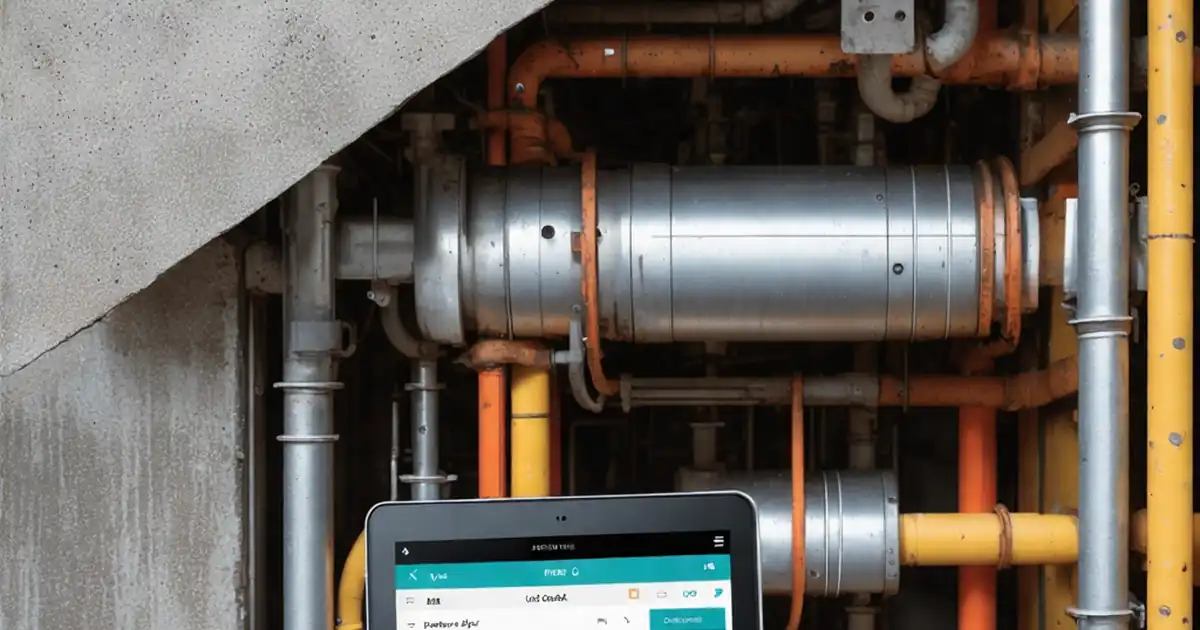
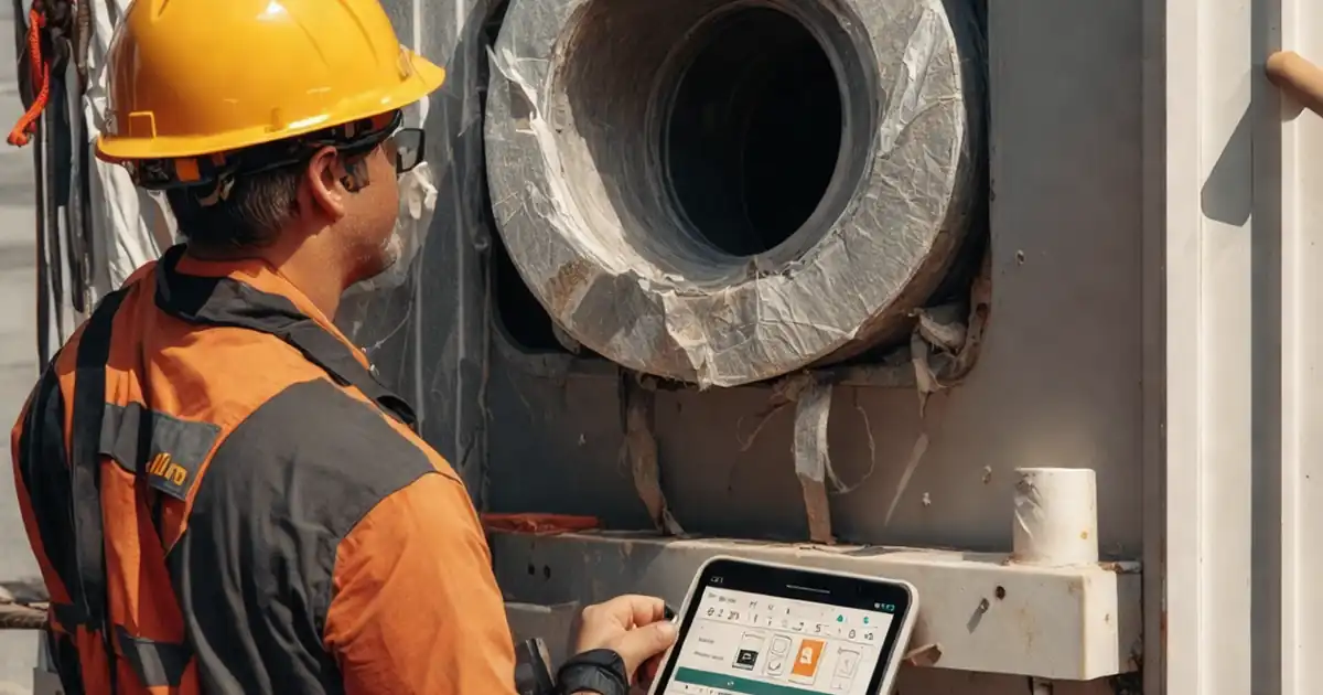
Detailing penetrations to protect thermal and airtight layers
Service penetrations can undermine façade performance if grommets, wraps, and sleeves are omitted or poorly installed. Each metallic element crossing the envelope needs a thermal interruption and airtight seal compatible with adjacent membranes. Inspect wrap thickness at multiple points and perform simple peel tests on tapes to validate adhesion. Borescopes help verify continuous bushings on through-bolts where access is limited. Coordinate with fire-stopping trades to ensure materials remain thermally and functionally compatible without creating new bridges. Acceptance cues include wrap thickness within tolerance, airtight seals passing peel tests, and zero visible metal bypasses. On a recent tower retrofit, adding thermal sleeves to cable tray supports removed a persistent cold strip identified by IR, raising surface temperatures by over 3 K and eliminating condensation at winter design conditions.
- Measure insulation wrap thickness at four quadrants.
- Perform 90° tape peel tests on samples.
- Verify continuous bushings on through-bolts.
- Coordinate with fire-stopping for compatibility.
- Capture borescope photos at tight locations.
How to use this interactive façade thermal bridge checklist
- Preparation: bring approved drawings, thermal calculations, manufacturer datasheets, calibrated torque wrench, feeler gauges, borescope, IR camera, hygrometer, smoke pencil, PPE, and QR labels. Confirm access and safe work areas are established.
- Open the checklist in interactive mode. Select the façade zone, gridlines, and detail type (bracket, slab edge, penetration). Preload relevant submittals for quick reference during inspection.
- During inspection, tick each item as completed, enter measured values (mm, N·m, °C, %RH), and attach annotated photos or short videos. Add comments tagging responsible trades for follow-up.
- For testing steps, record instrument models, calibration dates, and settings (emissivity, ΔT targets). Link observations to QR-labeled locations to maintain traceable records.
- Export the checklist as PDF/Excel for review. Route to contractor, consultant, and client for digital signatures. Confirm the QR code validates the final, non-editable report version.
- Archive the signed package with calculations, submittals, torque logs, and IR report. Update the project commissioning tracker and close the façade thermal bridge mitigation hold point.
Call to Action
- Start Checklist Tick off tasks, leave comments on items or the whole form, and export your completed report to PDF or Excel—with a built-in QR code for authenticity.
- Download Excel - Façade Thermal Bridge Mitigation Review
- Download PDF - Façade Thermal Bridge Mitigation Review
- View Image - Façade Thermal Bridge Mitigation Review
Cite & Embed
“Façade Thermal Bridge Mitigation Review by Quollnet”
with a link to
this source page.
FAQ
Question: What field tolerances matter most for thermal bridge mitigation at façade brackets?
Question: How do I validate that slab edge thermal breaks performed as modeled?
Question: Which tools are essential for inspecting penetrations without removing finishes?
Question: When should these inspections occur to avoid rework and delays?
Related Articles
Broader reading and guidance connected to this checklist topic.


Open Ncrs At Taking-over / Dlp: What Happens At Handover And How To Escalate

Requisition Form: Materials, Services, Budget Control, And Logs

Fidic Site Instruction Form – Free Download And Usage Tips

Related Checklists
Keep the workflow moving with nearby templates chosen from similar checklist content.