Method Statement: Deep Excavation Temporary Support Works Near Existing Structures and Services – Method Statement
AI-assisted method statement with matching ITP, PDF download, and Excel export.
More than a static template
Unlike a downloadable Word or PDF template, this method statement is an AI-assisted editable starting point connected directly to a matching Inspection and Test Plan. Every section is structured, project-adaptable, and ready to export.
- AI-assisted drafting — Customize every section with AI for your specific project scope.
- Linked ITP — A matching inspection and test plan is generated alongside the method statement.
- Multiple export formats — Download as a formatted PDF or editable Excel spreadsheet.
- Editable starting point, not a final document — Review, verify, and adjust all content against your project requirements before use.
Static template vs. Quollnet workflow
| Feature | Static template | Quollnet |
|---|---|---|
| Project-specific content | Manual fill-in required | AI-assisted customization |
| Linked ITP | Separate document, no link | Matching ITP included |
| Export formats | Usually PDF only | PDF and Excel |
| Structured sections | Free-form layout | 13 standardized sections |
| Saved to your account | Local file only | Cloud-saved, reusable |
| Content accuracy | You verify everything | AI-assisted, you still verify |
| Cost | Often free but time-intensive | Free to customize and download |
What you can customize
When you save this method statement to your account, every section becomes editable. The following 13 sections are included:
- Scope — Defines the activity and its boundaries.
- References — Standards, specifications, and drawings.
- Responsibilities — Roles and accountabilities.
- Resources — Labour, plant, and equipment summary.
- Materials — Materials and compliance requirements.
- Equipment — Tools and equipment details.
- Prerequisites — Hold points and pre-conditions.
- Method sequence — Step-by-step construction sequence.
- Safety controls — HSE risk controls and PPE.
- Environmental controls — Environmental mitigation measures.
- QA/QC — Quality inspection and test requirements.
- ITP — Inspection and Test Plan table (has its own page).
- Attachments — Referenced drawings and documentation.
Why this method statement is used
This method statement is used to define and communicate the approved procedure for carrying out method statement: deep excavation temporary support works near existing structures and services on site. It ensures the work is planned in advance, the correct resources and controls are in place, and all personnel understand responsibilities, sequence, quality requirements, and safety controls before work begins. It aligns site execution with the documented scope and acceptance expectations.
Who uses this method statement
This method statement is used by contractors, site supervisors, project engineers, QA/QC engineers, HSE officers, consultants, and client representatives. It serves as a shared reference for planning, execution, supervision, inspection, and approval of the activity on site.
When it is prepared and submitted
The method statement is prepared before the work activity starts and submitted as part of the pre-construction documentation package for review and approval.
Who reviews or approves it
The method statement is usually submitted to the client representative, consultant, resident engineer, or project management consultant for review and approval before the work commences.
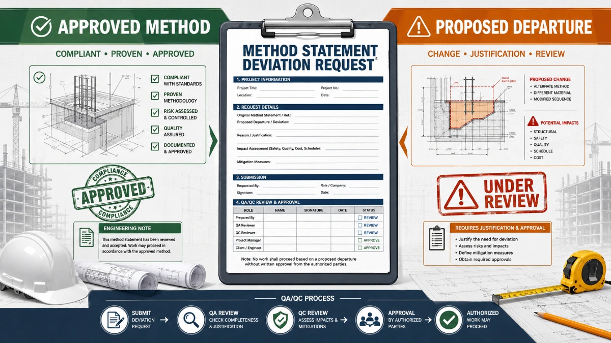
Important approval note
This method statement is an AI-assisted editable starting point, not a pre-approved document. Before use on any project, all content must be reviewed and approved by the relevant parties (superintendent, principal contractor, or client representative) in accordance with your contract and project quality plan.
For example: if your specification requires a departure from a referenced standard, that departure must be documented and approved separately — this method statement will not capture that automatically. Always verify against your applicable drawings, specifications, and regulatory requirements.
Method statement content
Scope
Purpose
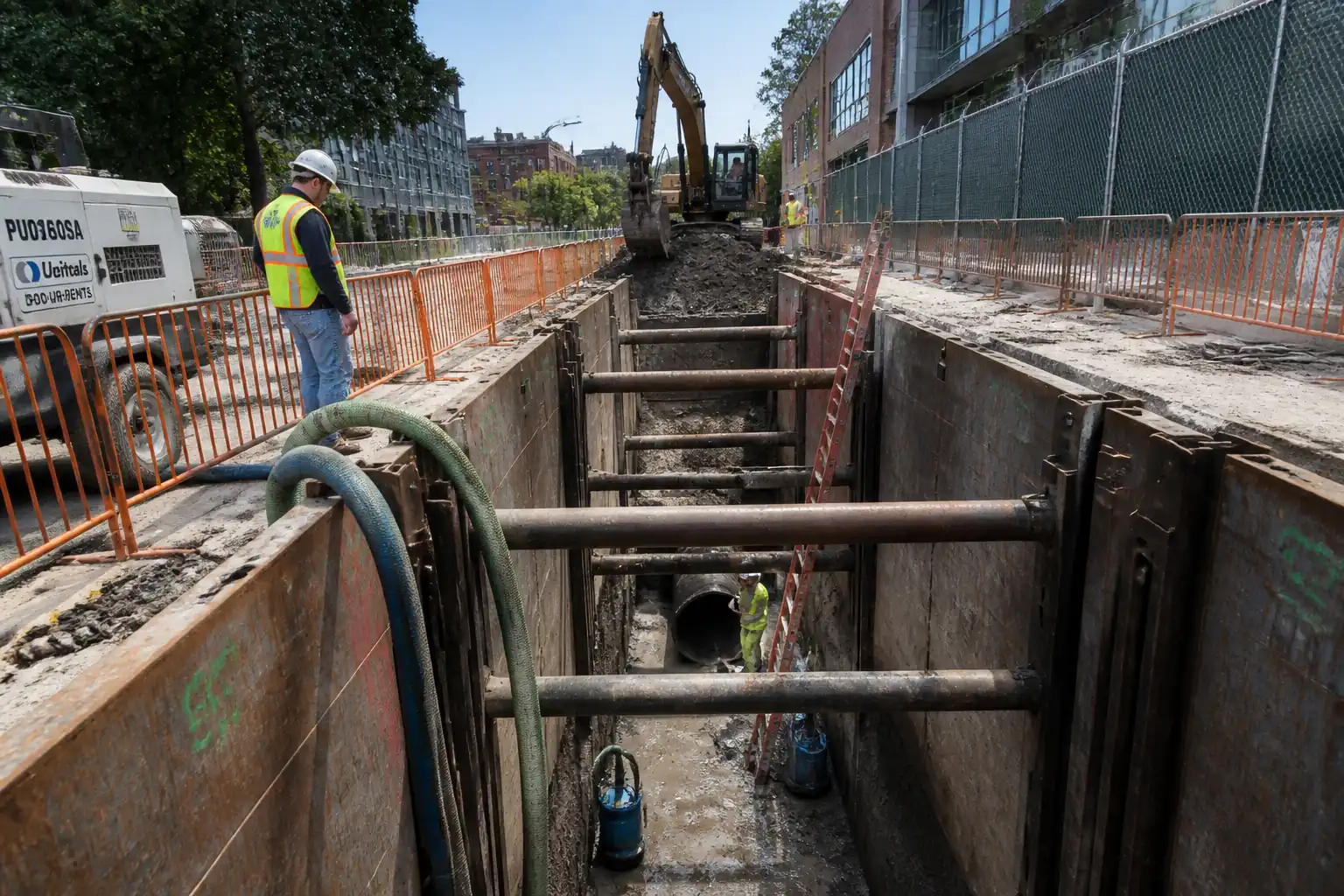
Define the procedure for deep excavation adjacent to existing structures and live services, including temporary support works (embedded retaining walls, struts/tiebacks), groundwater management, instrumentation/monitoring, settlement control, inspection hold points, and coordination among design and construction teams.
Extent
- Excavation depth: typically 4–15 m below existing ground level [Verify per project specifications].
- Plan area: per IFC drawings.
- Proximity constraints: excavation edge within 0.5–3.0 m of existing structures/services [Verify].
Inclusions
- Pre-construction surveys, utility detection and protection/diversions.
- Temporary works design coordination and checks per BS 5975 (or equivalent).
- Installation of embedded wall system (e.g., secant pile wall, sheet pile wall, or soldier pile and lagging) per approved design.
- Staged excavation and installation of internal bracing (walers/struts) and/or ground anchors.
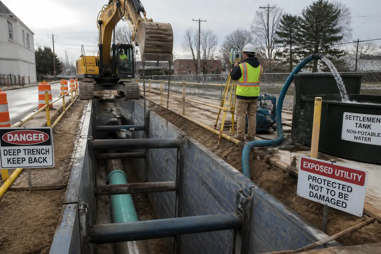
- Groundwater control (wellpoints/deep wells/sumps) and discharge management.
- Instrumentation and monitoring (inclinometers, settlement points, piezometers, strut load cells, building monitoring), trigger levels and response actions.
- Quality control, inspection and test plan (ITP) with hold/witness points.
- Emergency preparedness and response.
- Interface and coordination with geotechnical, structural, temporary works, and construction teams.
Exclusions
- Permanent works construction other than interfaces (e.g., capping beam/working slab where needed for temporary stability).
- Utility diversion construction beyond temporary support/protection unless specified.
Key Assumptions
- Temporary works design issued and checked by competent designer; CAT III check where required [Verify per project procedures].
- Monitoring and dewatering consents/permits in place before works commence.
- Adjacent asset owners are notified and access for monitoring is granted.
References
| Document Type | Reference / Number | Revision | Notes |
|---|---|---|---|
| Standard | BS 5975 | ||
| Standard | EN 1997 | Design, execution and verification of geotechnical structures | |
| Standard | EN 12063 | ||
| Standard | EN 1538 | ||
| Standard | EN 1536 | Applicable for secant pile walls if used | |
| Standard | EN 1537 | Anchor installation and testing | |
| Standard | ISO 18674 (series) | Instrumentation installation and data evaluation | |
| Standard | BS 6031 | ||
| Guidance | CIRIA C760 / C580 | Design/monitoring good practice | |
| Guidance | CIRIA C515 (or local equivalent) | ||
| Standard | EN 1090 (series) | Fabrication and welding of steel walers/struts | |
| Standard | ISO 5817 | Weld quality levels for NDT acceptance [Verify project class] | |
| Standard | ASTM/BS EN relevant (e.g., SPT, CPT) | Where applicable to verify soil parameters | |
| Regulation/Permit | Local environmental regulations | Discharge consents and sampling requirements [Verify] |
Responsibilities
| Role | Responsibility | Name / Party |
|---|---|---|
| TWC | Temporary Works Coordinator (TWC) | Contractor |
| TWD | Temporary Works Designer (TWD) | Designer |
| PM | Construction/Project Manager | Contractor |
| Geotech | Geotechnical Engineer | Designer/Contractor |
| IMC | Monitoring Specialist | Specialist |
| Surveyor | Land Surveyor | Contractor |
| Dewatering | Dewatering Manager | Specialist |
| HSE | HSE Manager | Contractor |
| QA/QC | QA/QC Engineer | Contractor |
| Utilities | Utilities Coordinator | Contractor |
| AP | Appointed Person / Lift Supervisor | Contractor |
| IC | Independent Checker/Asset Owner Rep | Independent |
Resources
| Resource Type | Description | Quantity | Remarks |
|---|---|---|---|
| Manpower | Excavation crew (operators, banksmen) | 8–12 | |
| Manpower | Piling/Sheet piling crew | 6–10 | |
| Manpower | Anchor drilling and stressing crew | 5–8 | |
| Manpower | Dewatering technicians | 3–5 | |
| Manpower | Instrumentation specialists | 2–4 |
Materials
| Material | Specification / Grade | Quantity | Remarks |
|---|---|---|---|
| Sheet piles | EN 10248 / EN 12063 | As per design | |
| Soldier piles / King posts | EN 10025-2 S355 | As per design | |
| Concrete for secant piles | C30/37–C40/50 slump S4/S5 [Verify] | As per design | |
| Cement grout | w/c 0.4–0.6; 28-day f_c ≥ 25–40 MPa [Verify] | As per design | |
| Ground anchor strand/tendon | f_pk 1770–1860 MPa (EN 10138) | As per design | |
| Steel walers and struts | S355, welds to ISO 5817 (B/C) [Verify] | As per design | |
| Lagging boards/precast panels | Strength/durability class [Verify] | As per design | |
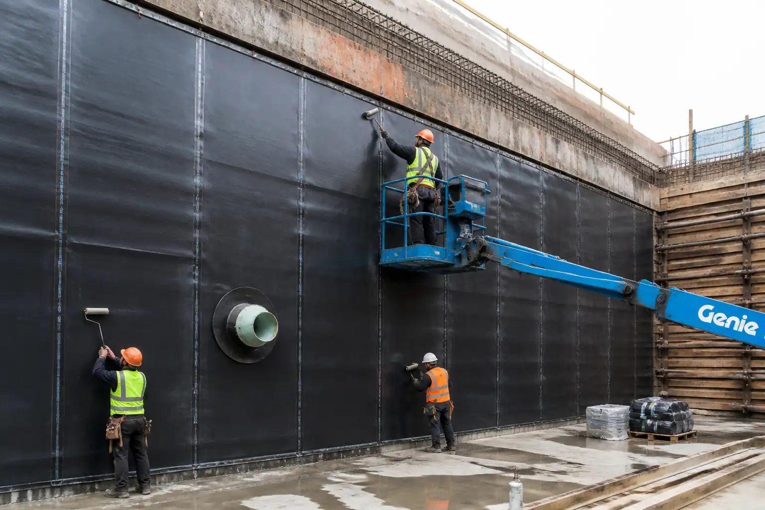
| Geotextile/drainage composite | EN 13249/13252 class [Verify] | As required | |
| Instrumentation | ISO 18674 compliant | As per monitoring plan |
Equipment
| Equipment | Capacity / Type | Quantity | Inspection Required |
|---|---|---|---|
| Excavators (20–35 t) | 2–3 | Daily checks, LOLER where applicable | |
| Vibratory hammer & powerpack | 30–60 kgm [Verify] | 1 | Service records |
| Bored piling rig | e.g., BG28 class [Verify] | 1 | Certificates, operator competency |
| Crawler crane | 50–80 t [Verify] | 1–2 | LOLER certs, lift plans |
| Anchor drill & grout plant | Drill 100–200 mm; pump 10–40 L/min | 1 set | Calibration logs |
| Wellpoint/deep well pumps | 5–50 L/s per well [Verify] | As required | Pump curves, maintenance logs |
| Total station/auto level | 1–2 | Calibration certs | |
| Geo drilling rig | 1 | Operator competency | |
| Temporary works access/edge systems | As required | Inspection before use |
Prerequisites
- Approved temporary works design and check certificates (CAT per project) and construction drawings.
- Temporary Works Register updated; appointments of TWC/TWS issued.
- Method Statement, Risk Assessment, and ITP approved.
- Permit-to-Dig (PTD), Excavation Permit, Lifting Plans, Hot Work Permit (if welding), Confined Space Permit (if required) [Verify per project HSE plan and local regulations].
- Utility surveys (GPR + EML) and trial pits completed, services positively identified/marked; isolation or protection agreed with owners.
- Pre-condition structural/settlement survey of adjacent assets completed with photographic record.
- Monitoring Plan approved including trigger/action levels; access arrangements with third parties secured.
- Dewatering design, discharge consent/permit, and receiving-water method approved; pump test plan approved.
- Traffic management plan and logistics routes established; laydown/stockpile areas defined.
- Baseline monitoring data collected for ≥7 days trend where practicable [Verify].
- Plant certifications, operator competencies, and lifting accessories certificates available.
- Emergency Response Plan (ERP) briefed; materials on standby: steel plates, sandbags, additional struts, generators, standby pumps.
- Environmental controls set up: silt tanks, oil-water separators, drip trays, spill kits.
- Stakeholder notification and work windows agreed (noise/vibration-sensitive receptors).
Method Sequence
| Step | Activity | Description | Responsibility | Inspection / Hold Point |
|---|---|---|---|---|
| 1 | Site establishment & survey control | Mobilize, fence site, install signage, welfare; establish survey control points away from excavation influence zone; verify coordinates/benchmarks. | Site Manager / Surveyor | Pre-start inspection |
| 2 | Utility detection and trial pits (HP-1) | GPR/EML scan and hand-dug/air-vac trial pits to expose services crossing or within 3 m of excavation. Mark and protect; install bridging/protection slabs if required. | Utilities Coordinator | Hold Point (HP-1) – Permit-to-Dig sign-off |
| 3 | Pre-condition/asset survey | Survey adjacent structures/pavements for cracks/levels; install settlement studs/targets where permitted. | Geotechnical Engineer / Surveyor | Witness by Employer/Asset Owner (as required) |
| 4 | Instrumentation installation (HP-2) | Install inclinometers behind wall line, settlement markers/prisms, piezometers, strut load cells; connect dataloggers/telemetry as specified. | Monitoring Specialist | Hold Point (HP-2) – Locations verified before drilling |
| 5 | Dewatering installation & pump test (HP-3) | Install wellpoints/deep wells/sumps and headers; conduct 4–24 h pump test; verify drawdown and discharge quality; set auto-start/standby. | Dewatering Manager | Hold Point (HP-3) – Pump test review |
| 6 | Guide wall/guide beam (if secant/diaphragm) | Cast guide walls and set alignment/verticality controls for bored/secant piles or trench panels. | TWD / Site Engineer | Survey check |
| 7 | Install embedded wall (HP-4) | Drive sheet piles or construct secant/soldier piles as designed. Provide toe penetration; check verticality and alignment; weld interlocks/walers as needed. | Piling Superintendent | Hold Point (HP-4) – Wall alignment/toe check |
| 8 | Initial excavation to first berm (HP-5) | Excavate in stages (max 0.5–1.5 m cuts) maintaining stand-off from services; install temporary berm; place lagging/shotcrete if soldier piles. | Site Manager | Hold Point (HP-5) – Level and stability check |
| 9 | Walers and struts – Stage 1 (HP-6) | Install walers and struts per design; torque bolts; pre-load struts and install load cells/gauges. | TWC / Steelwork Supervisor | Hold Point (HP-6) – Preload verification |
| 10 | Staged excavation to next level(s) (HP-7 at each stage) | Continue excavation in 0.5–1.5 m stages; after each cut, install next strut/waler level or anchors per design; update monitoring. | Site Manager / TWC | Hold Point (HP-7) – After each support level |
| 11 | Ground anchors (if used) (HP-8) | Drill, install tendon, primary/secondary grout; carry out suitability/performance/proof testing; lock-off at specified load; protect and record. | Anchor Specialist | Hold Point (HP-8) – Anchor test acceptance |
| 12 | Excavate to formation (HP-9) | Final excavation to base; trim formation; maintain drawdown; inspect for boils/heave; prepare for blinding/working slab if required. | Site Manager / Geotechnical Engineer | Hold Point (HP-9) – Base stability check |
| 13 | Working slab/blinding (if required) | Place blinding or working slab for stability and access; ensure joints/gaps do not compromise dewatering. | Site Engineer | Inspection |
| 14 | Ongoing monitoring & review | Daily to weekly monitoring per plan; review trigger exceedances; implement action plan (amber: review/adjust; red: stop, make safe, escalate). | Monitoring Specialist / TWC / Geotechnical Engineer | Routine and event-based reviews |
| 15 | Backfill and support removal (HP-10) | After permanent works achieve required strength/support, remove temporary struts/anchors sequentially as designed; backfill in layers and compact. | TWC / Site Manager | Hold Point (HP-10) – Removal sequencing |
| 16 | Reinstatement and demobilization | Reinstate utilities/protection; remove dewatering progressively; remove instrumentation (where allowed); finalize as-builts and handover. | Site Manager | Final inspection |
Health, Safety and Environment – Task-Specific Safety Controls
Key Hazards, Consequences, and Controls
1) Hazard: Excavation collapse/ground loss adjacent to structures
- Consequence: Serious injury/fatality, damage to adjacent buildings/services
- Controls: Design verified per BS 5975/EN 1997; staged excavation with support installed at defined levels; daily TWC inspections; no over-excavation; maintain berms; immediate installation of struts/anchors after reaching trigger level; emergency steel plates and backfill on standby
- PPE: Hard hat, boots, gloves, eye protection, high-vis
- Collective measures: Edge protection, access platforms, exclusion zones; engineered trench boxes where applicable
- Inspection/Permit: Excavation Permit; daily excavation checklist; Hold Points at each stage
2) Hazard: Underground utility strike (electric, gas, water, fiber)
- Consequence: Electrocution, explosion, flooding, service outage
- Controls: PTD with GPR/EML + trial pits; maintain 1 m no-dig buffer to live services; hand/air-vac digging in proximity; temporary protection slabs/sling supports; isolation/consents where possible
- PPE: Dielectric gloves (as required), insulated tools, arc-rated PPE for HV proximity [Verify]
- Collective measures: Barriers, warning signage, lockout/tagout where applicable
- Inspection/Permit: Permit-to-Dig; utility owner liaison approvals; standby emergency clamps/plugs for water mains
3) Hazard: Sudden water ingress/flooding due to groundwater or main burst
- Consequence: Drowning, basal heave, instability
- Controls: Dewatering with standby pumps and auto-start floats; high-level alarms; staged drawdown; base heave checks; emergency sump capacities and sandbags
- PPE: Waterproof boots, life jackets where flooding risk, gloves
- Collective measures: Safe egress ladders every 25 m; non-slip access; lighting and emergency power
- Inspection/Permit: Dewatering permit; pump maintenance logs; ERP drills
4) Hazard: Plant/crane/rig instability and lifting operations
- Consequence: Crush injury, collapse, dropped loads
- Controls: Certified cranes/rigs; outrigger mats; lift plans and dedicated AP/Lift Supervisor; wind thresholds [Verify]; taglines; exclusion zones; no lifting over live traffic/services where practicable
- PPE: Helmets with chin straps, gloves, safety footwear
- Collective measures: Barriers/spotters; radio comms; proximity alarms
- Inspection/Permit: LOLER/third-party certifications; pre-lift checks; lifting permit
5) Hazard: Working at height at excavation edges/within frames
- Consequence: Falls from height
- Controls: Edge protection (toe board, mid, top rails) or proprietary systems; MEWPs/scaffolds with design tags; harness only where collective protection not feasible
- PPE: Harness with double lanyard if required, helmet with chin strap
- Collective measures: Guardrails and platforms
- Inspection/Permit: Work at Height permit; scaffold inspections (weekly/after events)
6) Hazard: Falling objects (tools, strut components)
- Consequence: Head injury, fatality
- Controls: Tool lanyards; exclusion below; controlled lifting; netting where necessary
- PPE: Hard hat with chin strap, eye protection
- Collective measures: Overhead protection gantries where needed
- Inspection/Permit: TWC inspection before entry below
7) Hazard: Hot works (strut/waler welding)
- Consequence: Burns, fire, fumes
- Controls: Hot Work Permit; WPS/PQR; fire blankets/extinguishers; fire watch and gas testing if confined areas
- PPE: Welding shields, FR gloves/clothing, respiratory protection if needed
- Collective measures: Local extraction/ventilation
- Inspection/Permit: Hot Work Permit; equipment inspection
8) Hazard: Confined/limited access within excavation frames
- Consequence: Asphyxiation, restricted egress
- Controls: Atmosphere testing if suspected gases; rescue plan; maintain ladders at ≤25 m spacing; communication plan
- PPE: Gas detector (if required), harness for rescue, lighting
- Collective measures: Ventilation fans as required
- Inspection/Permit: Confined Space assessment/permit [Verify]
9) Hazard: Noise and vibration from piling/excavation
- Consequence: Hearing damage; nuisance; structural effects
- Controls: Select low-vibration methods where feasible; set PPV/LAeq limits [Verify]; real-time monitors; time restrictions; pre-condition surveys
- PPE: Hearing protection
- Collective measures: Acoustic screens where practicable
- Inspection/Permit: Noise/vibration monitoring records; local authority consents
10) Hazard: Traffic interface and plant-person interaction
- Consequence: Collision, injury
- Controls: One-way routes; pedestrian segregation; trained banksmen; proximity alarms; speed limits
- PPE: High-vis, safety boots, helmets
- Collective measures: Physical barriers, lighting
- Inspection/Permit: Traffic management plan; daily briefings
11) Hazard: Contaminated ground or ground gases
- Consequence: Exposure/illness, explosive atmospheres
- Controls: Review GI; gas monitoring; dust suppression; appropriate waste classification; COSHH controls
- PPE: Nitrile gloves, RPE (FFP3) as required, coveralls
- Collective measures: Decontamination area; sealed containers for spoil
- Inspection/Permit: Hazardous waste consignment notes; COSHH assessments
Note: All controls to be verified per project HSE plan and local regulations.
Environmental Controls
- Groundwater discharge: Treat via settlement tanks, silt bags, and oil-water separators. Sample TSS, pH, hydrocarbons per permit. Typical benchmark: TSS < 100 mg/L; pH 6.5–9.0 [Verify per permit].
- Drawdown management: Assess and limit drawdown radius to prevent settlement of adjacent assets. Use recharge wells if required. Monitor piezometers and settlement markers.
- Noise/vibration: Adopt low-vibration methods (press-in, pre-auger). Set site-specific limits [Verify]; typical building PPV 2–5 mm/s. Time restrictions and community notifications.
- Dust and air quality: Water sprays, wheel wash, covered stockpiles, speed control. Use atomized mist during dry/windy conditions. Monitor PM10/PM2.5 if required.
- Spoil and water management: Classify excavated materials; segregate contaminated spoil; track with waste transfer notes. Prevent runoff to drains; maintain spill kits.
- Fuel and chemical storage: Bunded areas (110% capacity), drip trays, secure taps. Refuel >10 m from drains/watercourses [Verify].
- Surface water protection: Silt curtains or barriers near receptors; lined sumps.
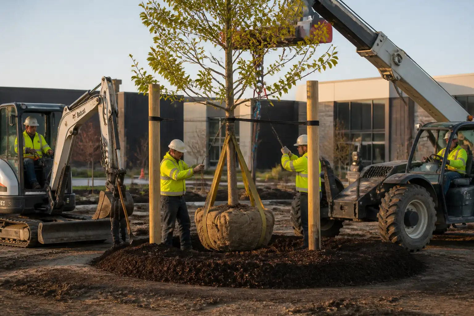
- Vegetation and trees: Protect root zones; avoid compaction within RPAs; install geogrids/mats for access if needed.
- Cultural heritage/archaeology: Stop-work and notify if finds encountered; follow watching brief if specified.
- Carbon/energy: Use Stage V/low-emission plant; optimize pump sizing; auto-stop systems; consolidate deliveries.
Quality Assurance and Quality Control
General QA/QC
- Implement ITP with clearly defined Hold Points (HP) and Witness Points (W).
- Maintain Temporary Works Register and as-built records including wall/strut/anchor layout and elevations.
Tolerances/Acceptance (typical benchmarks – Verify)
- Wall verticality: ≤1:100–1:200; plan position: ±25–50 mm.
- Toe/penetration: As design, verified by logs/survey.
- Strut preload: 80–110% of specified preload; lock-off within ±5%.
- Anchor testing: Per EN 1537; creep ≤ 2 mm at specified time at max test load; free-length elongation within ±10% theoretical; grout f_c ≥ 25–40 MPa at 28 days.
- Excavation levels: ±50 mm to each stage; base ±20 mm.
- Monitoring triggers: As per approved plan (typical settlement green <10 mm; wall deflection <0.5%H; strut force deviation <10%).
- Dewatering: Water level ≥1.0–1.5 m below base; discharge quality per permit.
Testing and Records
- Concrete/grout sampling per EN 206/EN 1537; cube/cylinder breaks at 7/28 days.
- Weld inspections per ISO 5817 quality level (C/B as specified); NDT extent typically 10–25% [Verify].
- Bolt torque/tension verification; mill certificates EN 10204 3.1 for steel; anchor tendon certificates.
- Instrumentation calibration certificates and installation records.
- Daily/weekly monitoring reports; trigger exceedance action logs.
- Non-conformance control, corrective actions, and trend reviews.
Hold Points (indicative IDs)
- HP-1: PTD and utility exposure/protection complete.
- HP-2: Instrumentation installed, baseline accepted.
- HP-3: Dewatering pump test accepted.
- HP-4: Embedded wall installation check (alignment, toe) accepted.
- HP-5: First excavation stage level/stability accepted.
- HP-6: Strut/waler pre-load accepted.
- HP-7: Each subsequent stage prior to proceeding deeper.
- HP-8: Anchor performance/proof testing accepted.
- HP-9: Base stability check accepted.
- HP-10: Approval to remove temporary supports/backfill.
Attachments
- Approved temporary works design drawings and calculation packs (with check certificates).
- Staging and sequencing drawings (levels of excavation, strut/tieback schedule).
- Monitoring Plan with trigger/action levels and reporting templates.
- Dewatering design and pump test procedure; discharge permit/consent.
- Permit-to-Dig forms and utility as-built drawings; trial pit records.
- Lift plans and lifting accessories certificates.
- Welding WPS/PQR, welder qualifications, and NDT plan.
- QA/QC ITP checklists and inspection forms.
- Emergency Response Plan (ERP) including inundation/collapse scenarios, contact list, and muster points.
- Traffic management plan and site logistics layout.
- Environmental Management Plan (noise/vibration/dust/sediment control).
- Pre-condition survey report and photographic records.
- As-built survey of embedded wall, supports, and instrumentation locations.
This content is a read-only public reference. Download or customize to get an editable version.
ITP preview
The first inspection activities from the linked ITP for Method Statement: Deep Excavation Temporary Support Works Near Existing Structures and Services:
| Activity | Inspection / Test | Acceptance Criteria | Responsibility | Record |
|---|---|---|---|---|
| Permit-to-Dig and utility verification (HP-1) | GPR/EML scans; trial pit records; PTD form | All utilities located/marked; method of protection/isolation approved; no mechanical excavation within 1 m of live services [Verify] | Utilities Coordinator / QA-QC / Engineer | PTD pack, trial pit photos, as-found survey |
| Instrumentation installation and baseline (HP-2) | Installation check; calibration certs; baseline readings | Locations/depths per design; baseline stable (variation within instrument precision over 48–72 h) [Verify] | Monitoring Specialist / Engineer | Instrumentation as-built, baseline report |
| Dewatering system and pump test (HP-3) | Drawdown verification; flow measurement; discharge sampling | Water level ≥1.0–1.5 m below base; stable drawdown without excessive settlement; discharge within permit limits [Verify] | Dewatering Manager / Geotechnical Engineer | Pump test log; lab results; approval memo |
Showing 3 of 10 inspection activities. View full ITP →
Related Inspection and Test Plan
An Inspection and Test Plan (ITP) is available for Method Statement: Deep Excavation Temporary Support Works Near Existing Structures and Services. The ITP defines the inspection activities, acceptance criteria, hold and witness points, responsible parties, and records required to verify the work described in this method statement.
View the Method Statement: Deep Excavation Temporary Support Works Near Existing Structures and Services ITP →Frequently asked questions
Continue with related Quollnet resources connected to this method statement.