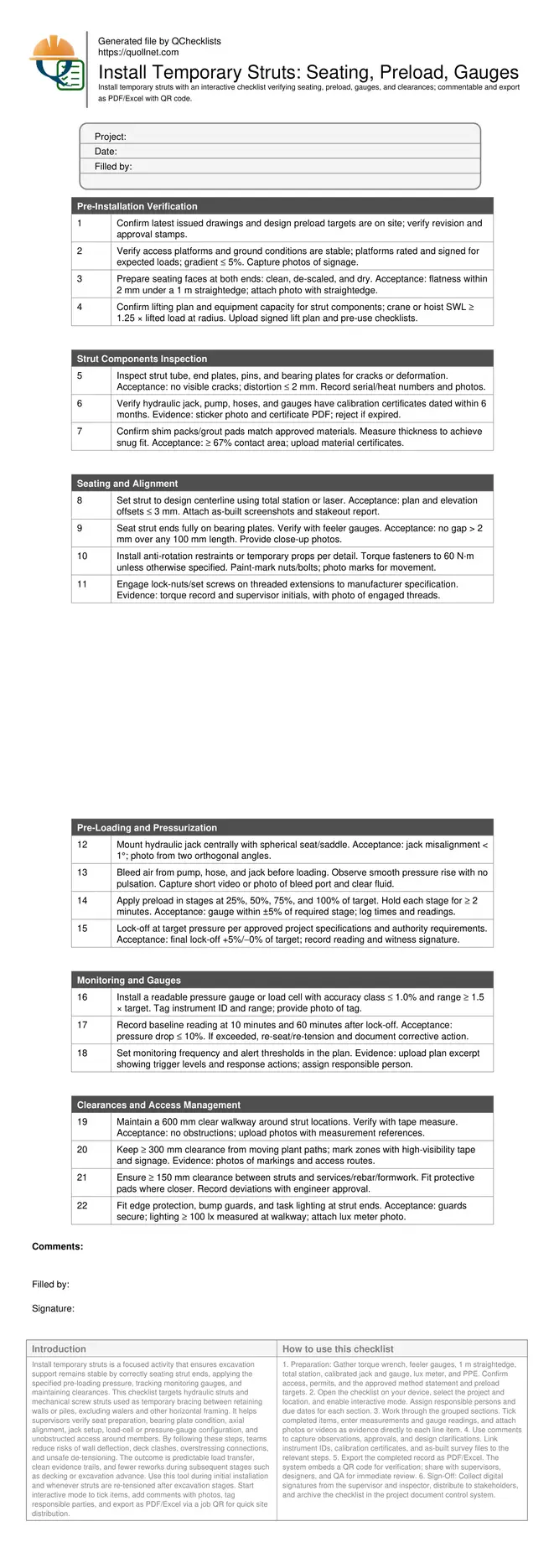
Install Temporary Struts: Seating, Preload, Gauges
Definition: Install temporary struts checklist for site engineers and foremen verifying seating faces, pre-loading pressures, monitoring gauges, and clearances during excavation support, excluding walers and focusing on safe, documented installation outcomes.
- Confirm strut seating, alignments, and preload pressures meet design.
- Prevent movement, protect excavations, and control load redistribution safely.
- Use calibrated gauges, torque tools, and documented pressure staging.
- Interactive, commentable checklist; export results with QR code verification.
Install temporary struts is a focused activity that ensures excavation support remains stable by correctly seating strut ends, applying the specified pre-loading pressure, tracking monitoring gauges, and maintaining clearances. This checklist targets hydraulic struts and mechanical screw struts used as temporary bracing between retaining walls or piles, excluding walers and other horizontal framing. It helps supervisors verify seat preparation, bearing plate condition, axial alignment, jack setup, load-cell or pressure-gauge configuration, and unobstructed access around members. By following these steps, teams reduce risks of wall deflection, deck clashes, overstressing connections, and unsafe de-tensioning. The outcome is predictable load transfer, clean evidence trails, and fewer reworks during subsequent stages such as decking or excavation advance. Use this tool during initial installation and whenever struts are re-tensioned after excavation stages. Start interactive mode to tick items, add comments with photos, tag responsible parties, and export as PDF/Excel via a job QR for quick site distribution.
- This checklist guides seating preparation, alignment, staged preloading, and gauge installation for temporary struts, ensuring stable excavation support. It reduces unplanned wall movements, improves documentation quality, and aligns field actions with the approved project specifications and authority requirements.
- Field-ready instructions combine practical tolerances with clear acceptance criteria: flatness within 2 mm under a 1 m straightedge, alignment offsets within 3 mm, gauge accuracy class ≤1.0%, and pressure staging with hold periods. Photo evidence, instrument IDs, and signatures create a reliable audit trail.
- Interactive online checklist with tick, comment, and export features secured by QR code. Supervisors attach calibration certificates, preload logs, and as-built survey screenshots, while teams receive automatic alerts for readings outside thresholds and can generate shareable PDF/Excel reports for shift handover.
Pre-Installation Verification
Strut Components Inspection
Seating and Alignment
Pre-Loading and Pressurization
Monitoring and Gauges
Clearances and Access Management
Seating and Preload Fundamentals
Effective temporary strut performance begins with sound seating and controlled preloading. Bearing surfaces must be clean, flat, and dry to transfer axial force without localized crushing or slip. Use a straightedge and feeler gauges to confirm flatness within 2 mm over 1 m, and verify at least two-thirds contact area with shim or grout packing. Align the strut on the design centerline using a total station, targeting ≤ 3 mm offset in plan and elevation to minimize bending from eccentricity. During preloading, bleed air from the hydraulic system, mount a spherical seat to accommodate small angular variations, and stage pressure increases with timed holds to allow seating and redistribution. Aim to lock off at the specified target, holding +5%/−0% tolerance to reduce early relaxation losses, and capture pressure logs with timestamps and witness signatures. Paint-mark fasteners to detect any post-loading movement and include close-up photographs in the record set.
- Flatness within 2 mm under a 1 m straightedge.
- Alignment offsets no greater than 3 mm.
- Staged preloading with timed holds and logs.
- Lock-off within +5%/−0% of target pressure.
Gauge Setup and Ongoing Monitoring
Pressure gauges or load cells are essential for confirming that struts are carrying the intended forces after lock-off. Select instruments with a range at least 1.5 times the target and accuracy class ≤ 1.0% to avoid over-ranging and retain meaningful resolution. Mount gauges within safe line-of-sight from access routes, orienting faces to minimize glare and providing protective guards against accidental impact. Capture instrument IDs, calibration dates, and ranges in the monitoring log. Establish a baseline at 10 and 60 minutes after lock-off to quantify seating losses; a drop exceeding 10% signals re-seating or re-tensioning. Define inspection frequency aligned with excavation advance and temperature swings, and include alert thresholds with clear response actions. Attach photos of gauge faces at each reading, and store digital logs centrally so trends, seasonal variations, or pump leakage can be differentiated from structural behavior.
- Gauge accuracy class ≤ 1.0% and adequate range.
- Baseline readings at 10 and 60 minutes.
- Drops over 10% trigger corrective action.
- Photograph gauge faces and record IDs.
Maintaining Clearances and Access
Clearances protect people, equipment, and the structure during ongoing works. Provide a continuous 600 mm walkway around strut locations to facilitate inspection without unsafe reaches. Maintain at least 300 mm separation from moving plant and 150 mm from services or embedded steel; where tighter spacing is unavoidable, fit protective padding and capture written approval. Ensure bump guards at strut ends, highlight edges with high-visibility markings, and provide task lighting to at least 100 lux at the walking surface for night or low-light operations. Coordinate crane paths and material routes to avoid contact with struts and gauge assemblies. Keep signage legible and update as the excavation progresses. Recording evidence—measurements, photos, and approval notes—supports transparent coordination and reduces rework risks when trades mobilize around the installed bracing.
- Walkway clearance minimum 600 mm maintained.
- 300 mm to plant; 150 mm to services.
- Fit bump guards and high-visibility markings.
- Provide task lighting of at least 100 lux.
How to Use This Interactive Strut Installation Checklist
- Preparation: Gather torque wrench, feeler gauges, 1 m straightedge, total station, calibrated jack and gauge, lux meter, and PPE. Confirm access, permits, and the approved method statement and preload targets.
- Open the checklist on your device, select the project and location, and enable interactive mode. Assign responsible persons and due dates for each section.
- Work through the grouped sections. Tick completed items, enter measurements and gauge readings, and attach photos or videos as evidence directly to each line item.
- Use comments to capture observations, approvals, and design clarifications. Link instrument IDs, calibration certificates, and as-built survey files to the relevant steps.
- Export the completed record as PDF/Excel. The system embeds a QR code for verification; share with supervisors, designers, and QA for immediate review.
- Sign-Off: Collect digital signatures from the supervisor and inspector, distribute to stakeholders, and archive the checklist in the project document control system.
Call to Action
- Start Checklist Tick off tasks, leave comments on items or the whole form, and export your completed report to PDF or Excel—with a built-in QR code for authenticity.
- Download Excel - Temporary Strut Installation (Seating, Preload, Gauges, Clearance)
- Download PDF - Temporary Strut Installation (Seating, Preload, Gauges, Clearance)
- View Image - Temporary Strut Installation (Seating, Preload, Gauges, Clearance)
Cite & Embed
“Temporary Strut Installation (Seating, Preload, Gauges, Clearance) by Quollnet”
with a link to
this source page.

FAQ
Question: What preload should I apply to a temporary strut?
Question: How do I verify proper end seating without using walers?
Question: What should I do if pressure drops after lock-off?
Question: How do I choose an appropriate gauge or load cell?
Related Articles
Broader reading and guidance connected to this checklist topic.


Related Checklists
Keep the workflow moving with nearby templates chosen from similar checklist content.