
Method Statement – Hydrostatic Pressure Leak Testing of Domestic Water Supply Networks – Method Statement
AI-assisted method statement with matching ITP, PDF download, and Excel export.
More than a static template
Unlike a downloadable Word or PDF template, this method statement is an AI-assisted editable starting point connected directly to a matching Inspection and Test Plan. Every section is structured, project-adaptable, and ready to export.
- AI-assisted drafting — Customize every section with AI for your specific project scope.
- Linked ITP — A matching inspection and test plan is generated alongside the method statement.
- Multiple export formats — Download as a formatted PDF or editable Excel spreadsheet.
- Editable starting point, not a final document — Review, verify, and adjust all content against your project requirements before use.
Static template vs. Quollnet workflow
| Feature | Static template | Quollnet |
|---|---|---|
| Project-specific content | Manual fill-in required | AI-assisted customization |
| Linked ITP | Separate document, no link | Matching ITP included |
| Export formats | Usually PDF only | PDF and Excel |
| Structured sections | Free-form layout | 13 standardized sections |
| Saved to your account | Local file only | Cloud-saved, reusable |
| Content accuracy | You verify everything | AI-assisted, you still verify |
| Cost | Often free but time-intensive | Free to customize and download |
What you can customize
When you save this method statement to your account, every section becomes editable. The following 13 sections are included:
- Scope — Defines the activity and its boundaries.
- References — Standards, specifications, and drawings.
- Responsibilities — Roles and accountabilities.
- Resources — Labour, plant, and equipment summary.
- Materials — Materials and compliance requirements.
- Equipment — Tools and equipment details.
- Prerequisites — Hold points and pre-conditions.
- Method sequence — Step-by-step construction sequence.
- Safety controls — HSE risk controls and PPE.
- Environmental controls — Environmental mitigation measures.
- QA/QC — Quality inspection and test requirements.
- ITP — Inspection and Test Plan table (has its own page).
- Attachments — Referenced drawings and documentation.
Why this method statement is used
This method statement is used to define and communicate the approved procedure for carrying out method statement – hydrostatic pressure leak testing of domestic water supply networks on site. It ensures the work is planned in advance, the correct resources and controls are in place, and all personnel understand responsibilities, sequence, quality requirements, and safety controls before work begins. It aligns site execution with the documented scope and acceptance expectations.
Who uses this method statement
This method statement is used by contractors, site supervisors, project engineers, QA/QC engineers, HSE officers, consultants, and client representatives. It serves as a shared reference for planning, execution, supervision, inspection, and approval of the activity on site.
When it is prepared and submitted
The method statement is prepared before the work activity starts and submitted as part of the pre-construction documentation package for review and approval.
Who reviews or approves it
The method statement is usually submitted to the client representative, consultant, resident engineer, or project management consultant for review and approval before the work commences.
Important approval note
This method statement is an AI-assisted editable starting point, not a pre-approved document. Before use on any project, all content must be reviewed and approved by the relevant parties (superintendent, principal contractor, or client representative) in accordance with your contract and project quality plan.
For example: if your specification requires a departure from a referenced standard, that departure must be documented and approved separately — this method statement will not capture that automatically. Always verify against your applicable drawings, specifications, and regulatory requirements.
Method statement content
Scope
Overview
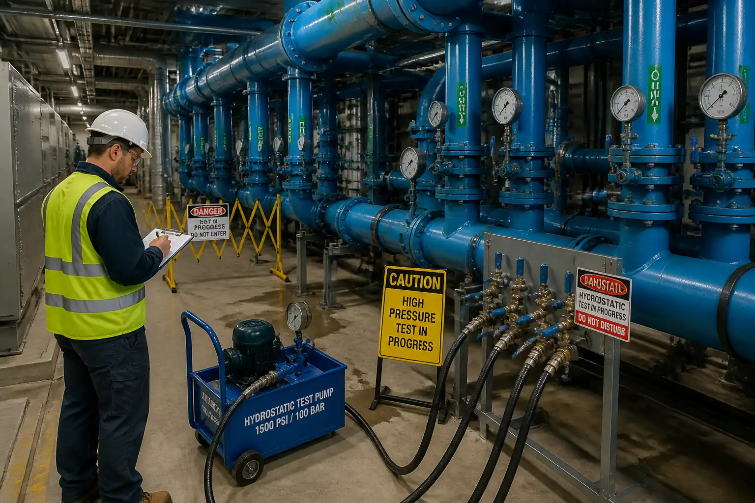
This method covers the preparation, isolation, hydrostatic pressure testing, leak inspection, monitoring, acceptance, and documentation for domestic cold and hot water supply networks within buildings. It includes temporary test manifolds, air bleeding, hand pump pressurization, calibrated gauge monitoring, joint inspection, controlled depressurization, and consultant sign-off at designated hold points.
Systems Covered
- Domestic cold water (DCW) distribution and risers
- Domestic hot water (DHW) distribution and return loops (tested cold unless otherwise specified)
- Service connections up to and including final isolation valves to fixtures/appliances (fixtures isolated/blanked during test)
Exclusions
- Disinfection/ chlorination (separate method statement/ITP)
- External buried water mains (refer to AWWA/EN 805 practices)
- Testing with compressed air (prohibited unless specifically approved)
Objectives
- Verify integrity of pipework, fittings, valves, and joints under hydrostatic pressure without leakage
- Confirm compliance with specified test pressure and duration
- Provide complete quality records with consultant approvals
Key Acceptance Criteria [Verify per project specifications]
- Test pressure: typically 1.5 × design operating pressure, not less than 10 bar and not more than 15 bar, limited by the lowest-rated component
- Hold duration: typically 2 hours after stabilization
- Permissible pressure drop after stabilization: 0 to 0.2 bar maximum with no visible leaks
- No makeup water addition after stabilization unless temperature-compensated per standard/manufacturer guidance
- All joints accessible and dry; no weeping, sweating, or dampness observed
- Gauge(s) class ≥ 1.0 per EN 837-1 (or better), in calibration
[All values to be verified against project specifications and manufacturer instructions]
References
| Document Type | Reference / Number | Revision | Notes |
|---|---|---|---|
| Standard | BS EN 806-4: Specifications for installations inside buildings conveying water for human consumption – Part 4: Installation (incl. pressure testing guidance) | Primary reference for internal building water systems testing. | |
| Guidance | UK HSE GS4 – Safety in pressure testing [Verify applicability per jurisdiction] | Safety principles for pressure testing operations. | |
| Standard | EN 837-1: Pressure gauges – Bourdon tubes – Dimensions, metrology, requirements and testing (gauge accuracy class) | Gauge selection and accuracy. | |
| Standard | ISO/IEC 17025: Testing and calibration laboratories – General requirements for competence (calibration certificates) | Calibration lab competence. | |
| Code/Standard | Local Plumbing Code/Authority requirements [Verify per project location] | Regulatory requirements for testing and permits. | |
| Project Document | Project Specifications and Approved Shop Drawings | Project-specific pressures, durations, materials, and zoning. |
Responsibilities
| Role | Responsibility | Name / Party |
|---|---|---|
| Construction/MEP Manager | Construction/MEP Manager | Contractor |
| QA/QC Engineer | QA/QC Engineer | Contractor |
| HSE Officer | HSE Officer | Contractor |
| Mechanical Site Engineer | Mechanical Site Engineer / Supervisor | Contractor |
| Plumbers / Pipefitters | Licensed Plumbers / Pipefitters | Contractor |
| Calibration Technician | Calibration Vendor / QA/QC | Third-Party / Contractor |
| Consultant Engineer | Consultant/Engineer | Consultant |
Resources
| Resource Type | Description | Quantity | Remarks |
|---|---|---|---|
| Manpower | 1 Mechanical Site Engineer, 1 Supervisor | 2 | Adjust per zone size |
| Manpower | 2–4 Licensed Plumbers/Pipefitters | 2–4 | |
| Manpower | 1 QA/QC Engineer or Inspector | 1 | |
| Manpower | 1 HSE Officer | 1 |
Materials
| Material | Specification / Grade | Quantity | Remarks |
|---|---|---|---|
| Water (potable) | Clean, non-corrosive | As required to fill zone | |
| Carbon steel/Brass/Plastic as compatible | Rated for ≥ 1.5× operating pressure | As required | |
| PTFE | Potable-water approved | As required |
Equipment
| Equipment | Capacity / Type | Quantity | Inspection Required |
|---|---|---|---|
| Hand pump | Up to 25 bar | 1 | Pre-use inspection |
| Bourdon/digital gauges | 0–25 bar typical | 2 | Calibration valid (ISO/IEC 17025) |
| IR/contact thermometer | 2 | Pre-use check | |
| HP hoses/valves | As required | Visual check | |
| Barricades/LOTO | As required | Pre-use check | |
| Drain hoses, trays | As required | Visual check |
Prerequisites
- Approved Method Statement and ITP on file; Risk Assessment and Permit to Test issued [Verify per project HSE plan and local regulations].
- Mechanical completion of the test zone: pipework installed, joints complete, supports/anchors in place, valves operational, joints accessible and not concealed.
- Sensitive components isolated or removed: water meters, PRVs, pressure/temperature gauges, cartridge mixers, flexible connectors, expansion vessels, water heaters, filter housings (use blanks/bypasses as applicable).
- All temporary end caps/blanking plates rated ≥ test pressure and properly gasketed.
- Gauges calibrated within 6 months (or per project), certificates available; gauge range 1.5–2× test pressure, accuracy class ≥ 1.0 EN 837-1.
- Test pressure confirmed: 1.5× design operating pressure, typically 10–15 bar [Verify per project specifications] and not exceeding the lowest-rated component or manufacturer limit (especially thermoplastics/MLCP).
- Test medium: clean potable water at ambient temperature; ensure no risk of freezing or overheating.
- Drains identified and protected; discharge route arranged to avoid flooding/erosion; finishes protected.
- Air release/high-point vents identified and operable.
- Instruments for temperature logging available; initial ambient and water temperatures recorded.
- Exclusion/barricade plan in place; emergency stop/relief arrangements verified.
- Inspection Request (IR) raised for Consultant hold point: Pre-test setup verification.
Method Sequence
| Step | Activity | Description | Responsibility | Inspection / Hold Point |
|---|---|---|---|---|
| 1 | Zone verification & isolation | Confirm the test boundary on latest approved drawings; tag and lock closed isolation valves; install blinds/caps at fixture branches; verify no cross-connection to live systems. | Site Engineer / Supervisor | Joint pre-test walkdown with QA/QC |
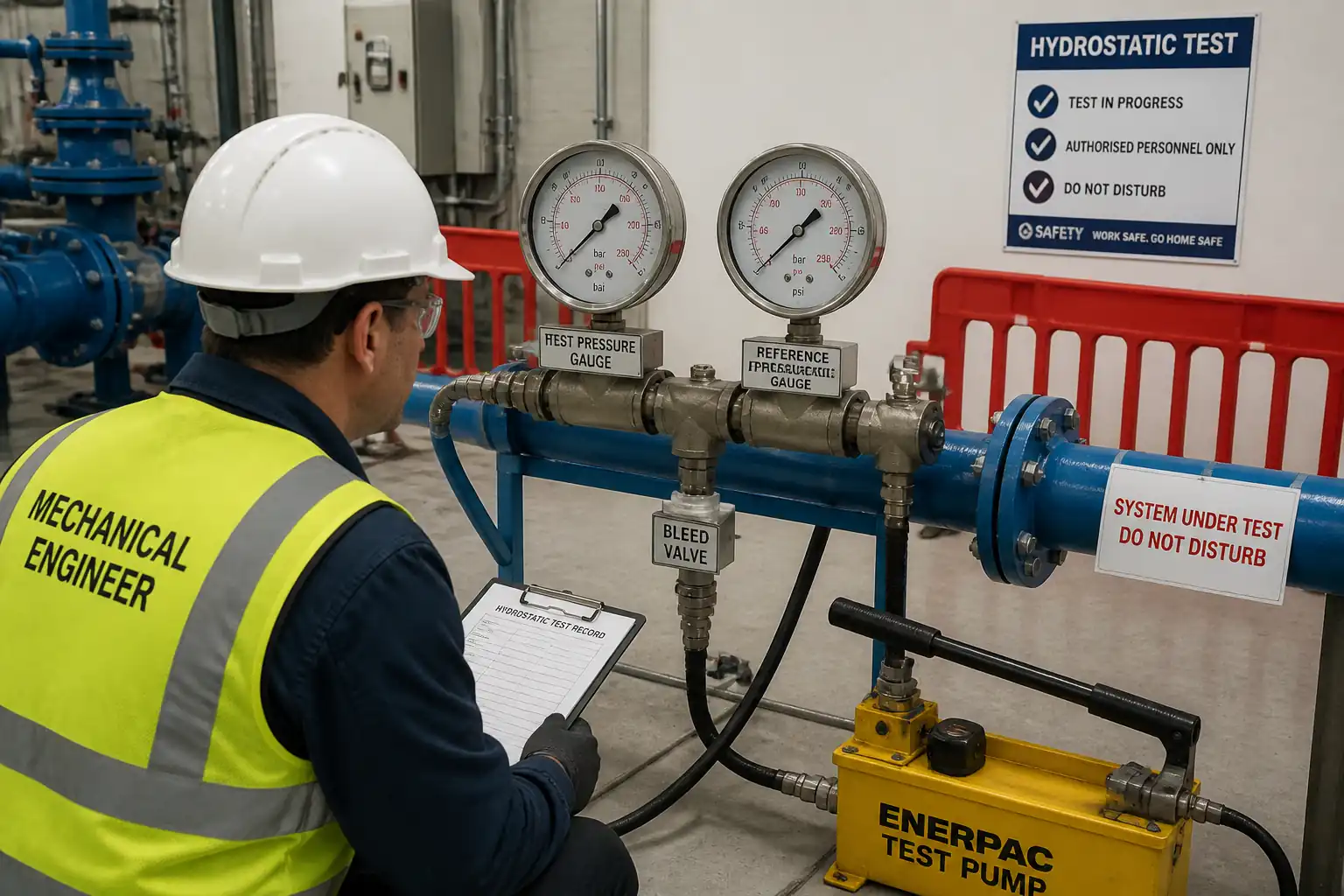
| 2 | Install test manifold & gauges | Connect hand pump manifold with isolation valve, non-return valve, and relief valve (≤110% of target pressure). Install two calibrated gauges: at manifold and remote point. | Plumber / QA/QC | Visual and torque checks |
| 3 | Filling and de-aeration | Fill from lowest point at low flow to avoid entrained air. Open all high-point vents and local fixture stub vents to expel air; close in sequence as water appears bubble-free. | Plumber | Observe vent points |
| 4 | Initial pressurization & stabilization | Increase pressure gradually at ≤1 bar/min to reach test pressure (typically 10–15 bar). Hold for 30 min to stabilize material/temperature. For thermoplastics, follow manufacturer step-test if required [Verify per project]. | Site Engineer / Plumber | Gauge reading and leak watch |
| 5 | Main test hold | Maintain stabilized test pressure for 2 hours. Record pressure and temperature at 0, 5, 10, 15 min, then every 15 min until completion. Do not add water after stabilization unless temperature-compensated and agreed. | QA/QC / Site Engineer | Continuous monitoring |
| 6 | Leak inspection | Visually inspect all accessible joints, unions, valves, riser flanges, and branch connections for moisture. Use tissue/indicator where necessary. Do not tighten under pressure; if leak found, depressurize before repair. | Supervisor / Plumber | Joint-by-joint check |
| 7 | Depressurization & draining | After acceptance, slowly reduce pressure via bleed valve to avoid water hammer. Drain to designated points; capture spills; remove manifold and reinstall permanent components. | Plumber | Controlled discharge |
| 8 | Rectification & retest (if required) | If criteria not met, mark and repair defects after depressurization. Wait cure time per manufacturer. Refill, vent, and repeat test sequence. | Supervisor / Plumber | Post-repair check |
| 9 | Documentation & sign-off | Compile logs, gauge certificates, IR approvals, and test certificate. Update as-builts with tested zones and dates. | QA/QC Engineer | Document review |
Safety Controls
Task-specific hazards and controls
1) Hazard: Stored hydraulic energy and component burst
- Consequence: Serious injury from jetting water/fragment impact
- Engineering/Procedural Control: Use water only (no compressed air); install pressure relief valve set ≤110% of test pressure; increase pressure ≤1 bar/min; establish 2 m exclusion zone around manifolds; never stand over or in line with temporary fittings; verify all components are pressure-rated
- Required PPE: Safety goggles or face shield, gloves, safety boots, long sleeves
- Collective Measures: Barricades and warning signage; lockable valves; remote reading of gauges where possible
- Inspection/Permit/Supervision: Permit to Test; pre-use inspection of pump/hoses; supervisor present; Consultant hold point per ITP
2) Hazard: Component failure at weak joint or cap
- Consequence: Flooding, slips, water damage
- Engineering/Procedural Control: Temporary caps/blinds rated ≥ test pressure; torque per manufacturer; use drip trays; protect finishes; maintain clear escape path for water to drains
- Required PPE: Waterproof boots, gloves
- Collective Measures: Floor protection, drain routing, spill kits
- Inspection/Permit/Supervision: Pre-test walkdown checklist; verify gaskets and fasteners; HSE oversight
3) Hazard: Air entrapment leading to unsafe stored energy
- Consequence: Pipe movement, sudden decompression
- Engineering/Procedural Control: Fill from lowest point; open all high-point vents; confirm bubble-free discharge; prohibit compressed air testing
- Required PPE: Eye protection, gloves
- Collective Measures: Dedicated venting plan; labeling of vent points
- Inspection/Permit/Supervision: Supervisor sign-off on de-aeration checklist
4) Hazard: Water and electricity interaction in plant rooms
- Consequence: Electric shock, equipment damage
- Engineering/Procedural Control: De-energize nearby non-essential circuits; cover panels; route drains away from electrical equipment
- Required PPE: Dielectric gloves when near panels, insulated tools
- Collective Measures: LOTO per electrical PTW; barriers around MCCs/DBs
- Inspection/Permit/Supervision: Electrical LOTO verification; HSE inspection [Verify per project HSE plan and local regulations]
5) Hazard: Working at height (risers/ceilings) to access vents/joints
- Consequence: Falls from ladders/platforms
- Engineering/Procedural Control: Use podium steps or mobile towers; maintain three points of contact; no overreaching; tie-off where required
- Required PPE: Hard hat, harness when applicable, non-slip footwear
- Collective Measures: Certified access equipment; edge protection
- Inspection/Permit/Supervision: Work at Height permit; equipment inspection tags; competent operator
6) Hazard: Manual handling of pumps, hoses, blinds
- Consequence: Strains, crush injuries
- Engineering/Procedural Control: Team lift; use trolleys; pre-plan lifts; keep good posture
- Required PPE: Gloves, safety footwear
- Collective Measures: Mechanical aids available
- Inspection/Permit/Supervision: Manual handling briefing (TBT)
7) Hazard: Noise during venting or sudden releases
- Consequence: Hearing damage, startle reactions
- Engineering/Procedural Control: Controlled venting; avoid rapid discharge
- Required PPE: Hearing protection when required
- Collective Measures: Exclusion during depressurization
- Inspection/Permit/Supervision: Supervisor authorization before venting
8) Hazard: Legionella/aerosolization during warm water testing
- Consequence: Respiratory illness
- Engineering/Procedural Control: Test cold where practical; minimize spray; discharge to closed drains; flush to sewer
- Required PPE: Respiratory protection if aerosol risk identified
- Collective Measures: Use hoses to submerge discharge; avoid misting
- Inspection/Permit/Supervision: HSE review of method [Verify per project HSE plan]
Emergency Preparedness: Identify isolation points and emergency drains; keep spill kits and wet vacuum on hand; know nearest power isolation and first aid kit locations.
Environmental Controls
- Water Use Minimization: Test by zones to reduce volume; record fill volumes; reuse water for subsequent tests where cleanliness allows.
- Controlled Discharge: Route drain hoses to approved floor drains or temporary tanks; avoid discharge onto unfinished floors; secure hose ends to prevent whipping.
- Protection of Finishes: Lay protection sheets and drip trays beneath manifolds and susceptible areas; immediately clean spills.
- Sediment/Contaminant Control: If debris present from flushing, filter before discharge; no discharge of oils or chemicals; use only potable water.
- Noise and Nuisance: Schedule testing in normal hours; notify adjacent tenants/areas; maintain barriers and signage.
- Waste Management: Collect damaged gaskets/tape and dispose per site waste plan; no materials left in risers/ceilings.
- Regulatory Compliance: Sewer discharge approvals where required; adhere to local authority/environmental regulations [Verify per project requirements].
QA/QC
Hold/Witness Points
- HOLD: Pre-test setup verification (zone isolation, instrumentation, blinds)
- WITNESS: Initial pressurization and stabilization (optional per Consultant)
- HOLD: Main test acceptance and readings review
- HOLD: Documentation and final Test Certificate sign-off
Measuring & Test Equipment (M&TE)
- Pressure gauges: EN 837-1 class ≥ 1.0; range 1.5–2× test pressure; calibration ≤ 6 months (ISO/IEC 17025)
- Thermometers: accuracy ±0.5°C recommended
- Relief valve: set ≤110% of target pressure; functional check before use
Test Parameters [Verify per project specifications]
- Test pressure: 1.5× design operating pressure, typically 10–15 bar; do not exceed lowest-rated component
- Pressurization rate: ≤1 bar/min
- Stabilization: 30 min at test pressure (or per pipe material-specific procedure)
- Hold time: 2 hours after stabilization
- Acceptance: No visible leakage; pressure drop 0 to ≤0.2 bar after temperature stabilization; no makeup water added unless temperature-compensated and agreed
Temperature Compensation
- Record ambient and water temperatures. If temperature change is observed during hold, apply standard/manufacturer correction or repeat test after thermal equilibrium. For plastics (PEX/PE/MLCP), follow manufacturer’s creep/relaxation test method (e.g., stepped pressurization with interim depressurization) [Verify per project].
Documentation
- Pre-test checklist, gauge calibration certificates, risk assessment/permit, pressure-temperature logs, leak inspection checklist, NCR/CCR (if any), IRs, and final Test Certificate with zone diagram and acceptance statement.
Non-Conformance
- Stop test upon significant pressure loss or leakage. Depressurize, repair per approved procedure, allow cure time, and retest complete sequence. Record NCR and corrective actions.
Attachments
- Example Pressure Test Certificate (with zone ID, gauge serials, pressure/temperature log, acceptance statement)
- Pre-test Checklist (isolation, blinds, vents, protection)
- Risk Assessment and Permit to Test template
- Gauge Calibration Certificates (ISO/IEC 17025)
- Test Manifold Schematic (with relief valve setting)
- As-built/Shop Drawing extract highlighting test boundaries
- Emergency/Spill Response Plan
This content is a read-only public reference. Download or customize to get an editable version.
ITP preview
The first inspection activities from the linked ITP for Method Statement – Hydrostatic Pressure Leak Testing of Domestic Water Supply Networks:
| Activity | Inspection / Test | Acceptance Criteria | Responsibility | Record |
|---|---|---|---|---|
| Review of method, ITP, and permits | Method, ITP, RA/Permit approved | Approved for construction/use | QA/QC Engineer / Consultant | Approved Method, ITP, RA, PTW |
| Material and component verification | Components installed and rated ≥ test pressure | Conform to specs/drawings | QA/QC Engineer | Inspection Request (IR), checklists |
| Instrumentation calibration check | Gauge class and range per EN 837-1; calibration valid | Valid ISO/IEC 17025 certs | QA/QC Engineer | Calibration certificates log |
Showing 3 of 9 inspection activities. View full ITP →
Related Inspection and Test Plan
An Inspection and Test Plan (ITP) is available for Method Statement – Hydrostatic Pressure Leak Testing of Domestic Water Supply Networks. The ITP defines the inspection activities, acceptance criteria, hold and witness points, responsible parties, and records required to verify the work described in this method statement.
View the Method Statement – Hydrostatic Pressure Leak Testing of Domestic Water Supply Networks ITP →Frequently asked questions
Continue with related Quollnet resources connected to this method statement.