
Method Statement: Pneumatic Testing of Oil & Gas Piping Systems – Method Statement
AI-assisted method statement with matching ITP, PDF download, and Excel export.
More than a static template
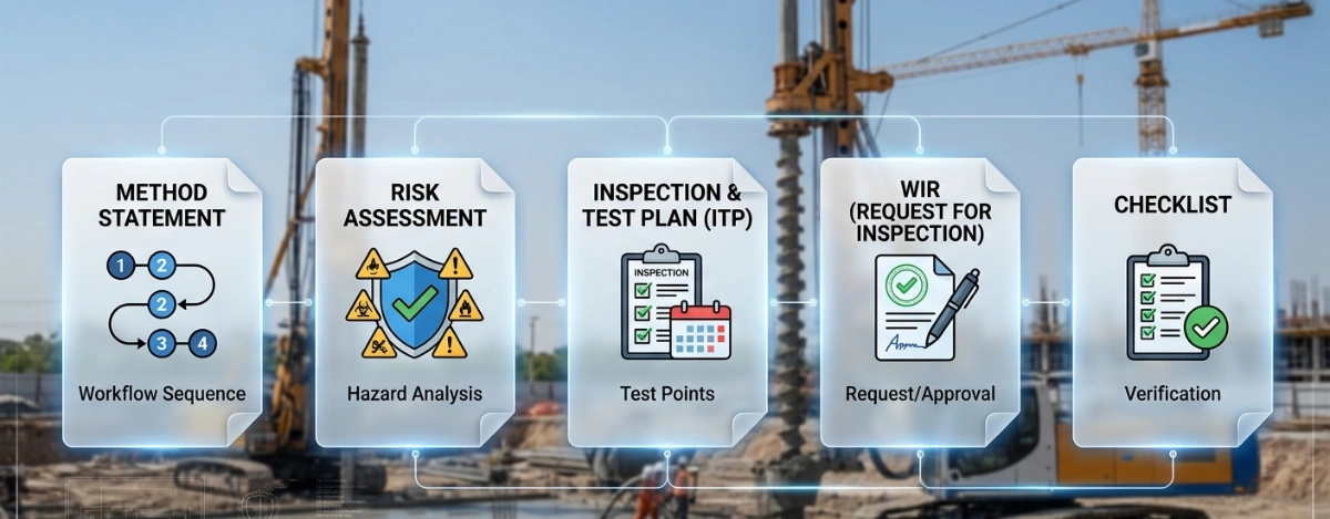
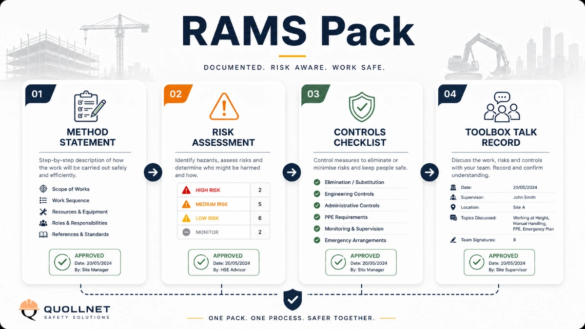
Unlike a downloadable Word or PDF template, this method statement is an AI-assisted editable starting point connected directly to a matching Inspection and Test Plan. Every section is structured, project-adaptable, and ready to export.
- AI-assisted drafting — Customize every section with AI for your specific project scope.
- Linked ITP — A matching inspection and test plan is generated alongside the method statement.
- Multiple export formats — Download as a formatted PDF or editable Excel spreadsheet.
- Editable starting point, not a final document — Review, verify, and adjust all content against your project requirements before use.
Static template vs. Quollnet workflow
| Feature | Static template | Quollnet |
|---|---|---|
| Project-specific content | Manual fill-in required | AI-assisted customization |
| Linked ITP | Separate document, no link | Matching ITP included |
| Export formats | Usually PDF only | PDF and Excel |
| Structured sections | Free-form layout | 13 standardized sections |
| Saved to your account | Local file only | Cloud-saved, reusable |
| Content accuracy | You verify everything | AI-assisted, you still verify |
| Cost | Often free but time-intensive | Free to customize and download |
What you can customize
When you save this method statement to your account, every section becomes editable. The following 13 sections are included:
- Scope — Defines the activity and its boundaries.
- References — Standards, specifications, and drawings.
- Responsibilities — Roles and accountabilities.
- Resources — Labour, plant, and equipment summary.
- Materials — Materials and compliance requirements.
- Equipment — Tools and equipment details.
- Prerequisites — Hold points and pre-conditions.
- Method sequence — Step-by-step construction sequence.
- Safety controls — HSE risk controls and PPE.
- Environmental controls — Environmental mitigation measures.
- QA/QC — Quality inspection and test requirements.
- ITP — Inspection and Test Plan table (has its own page).
- Attachments — Referenced drawings and documentation.
Why this method statement is used
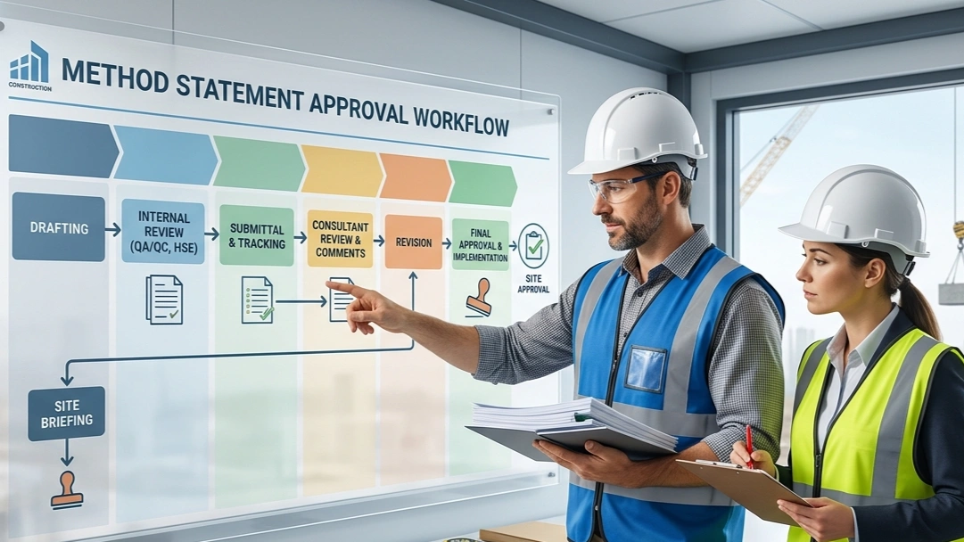
This method statement is used to define and communicate the approved procedure for carrying out method statement: pneumatic testing of oil & gas piping systems on site. It ensures the work is planned in advance, the correct resources and controls are in place, and all personnel understand responsibilities, sequence, quality requirements, and safety controls before work begins. It aligns site execution with the documented scope and acceptance expectations.
Who uses this method statement
This method statement is used by contractors, site supervisors, project engineers, QA/QC engineers, HSE officers, consultants, and client representatives. It serves as a shared reference for planning, execution, supervision, inspection, and approval of the activity on site.
When it is prepared and submitted
The method statement is prepared before the work activity starts and submitted as part of the pre-construction documentation package for review and approval.
Who reviews or approves it
The method statement is usually submitted to the client representative, consultant, resident engineer, or project management consultant for review and approval before the work commences.
Important approval note
This method statement is an AI-assisted editable starting point, not a pre-approved document. Before use on any project, all content must be reviewed and approved by the relevant parties (superintendent, principal contractor, or client representative) in accordance with your contract and project quality plan.
For example: if your specification requires a departure from a referenced standard, that departure must be documented and approved separately — this method statement will not capture that automatically. Always verify against your applicable drawings, specifications, and regulatory requirements.
Method statement content
Scope
Overview
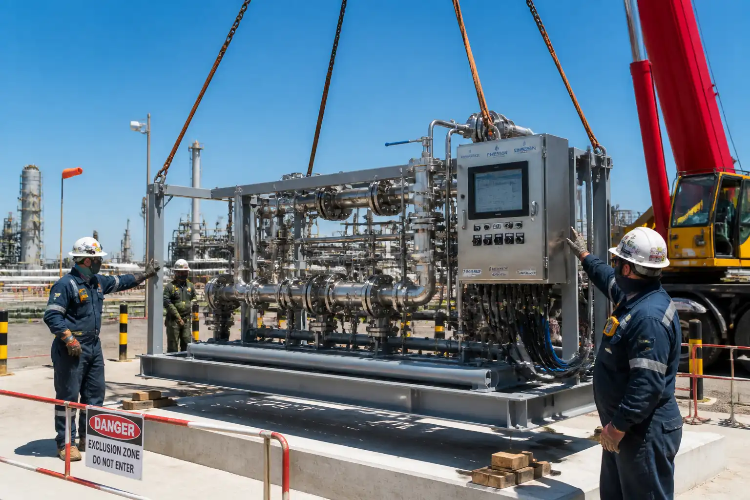
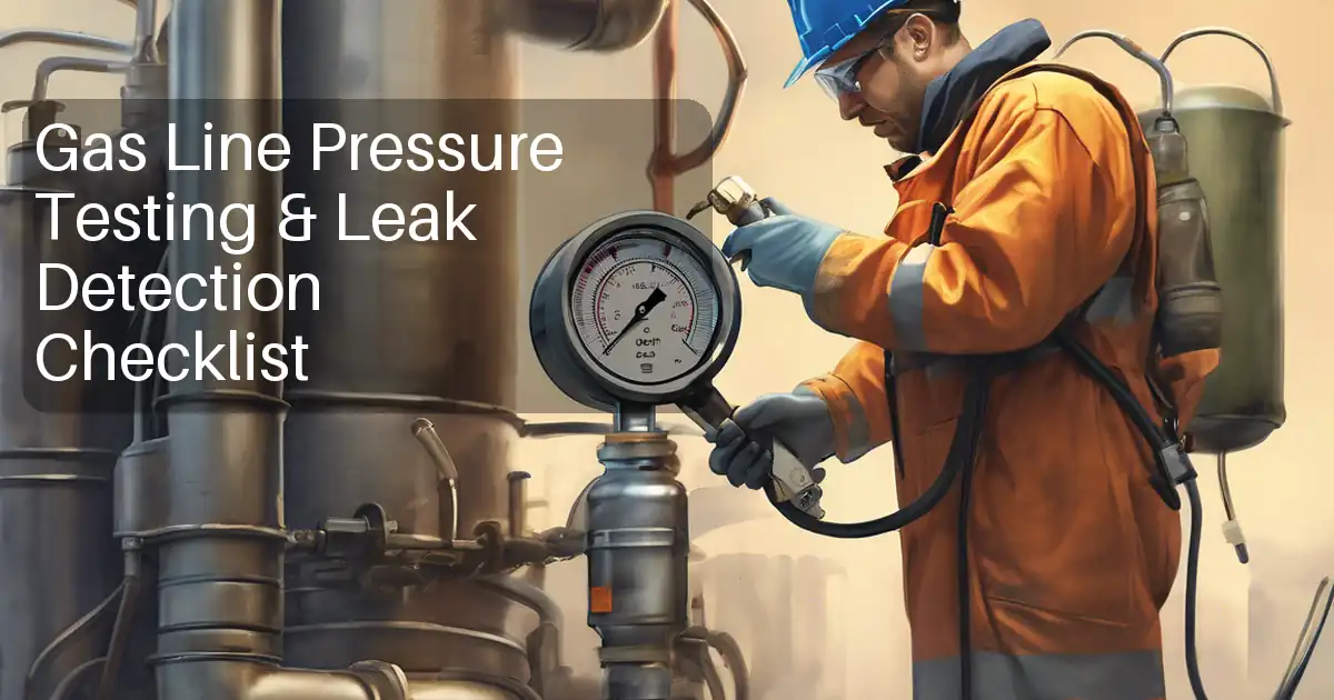
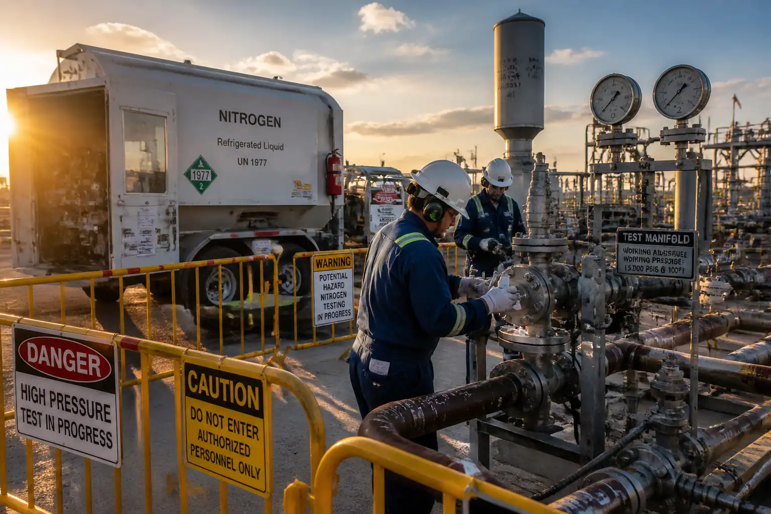
This method statement defines the controlled procedure for pneumatic pressure testing of oil and gas piping systems when hydrostatic testing is not suitable (e.g., inability to drain, contamination concerns, equipment duty limitations, or freezing risk). It details required risk assessment, test boundary definition, test medium control (air or inert gas such as nitrogen), exclusion zones, pressure increments, leak detection, instrument calibration, emergency response, QA/QC controls, acceptance criteria, and documentation.
Systems Covered
- Process, utility, and instrument air/gas piping designed to ASME B31.3/B31.4/B31.8 or equivalent.
- Skids, modules, and pipework spools where pneumatic testing is approved by the Engineer.
Exclusions
- Hydrostatic testing procedures (separate method).
- Pressure vessels and tanks (refer to applicable vessel code procedures).
Objectives
- Demonstrate piping integrity at specified test pressure without leakage or distress.
- Conduct testing with minimized risk due to stored energy in compressed gas.
Constraints
- Pneumatic tests shall only be performed after a documented risk assessment and Engineer approval.
- Inert gas (nitrogen) is preferred for hydrocarbon service; oxygen shall never be used. [Verify per project HSE plan and local regulations]
References
| Document Type | Reference / Number | Revision | Notes |
|---|---|---|---|
| ASME B31.3 Process Piping (Leak and pneumatic test provisions) | Pneumatic test pressure ≥ 1.1 × design pressure; metal temperature ≥ MDMT + 30°F (17°C). [Verify project edition] | ||
| ASME B31.4 / ASME B31.8 (where applicable to liquid/gas transmission piping) | Use where system is designed to these codes. [Verify edition] | ||
| ASME BPVC Section V, Article 10 (Leak Testing) | General practices for leak testing methods and examination. | ||
| ASTM E515/E515M (Bubble Leak Testing) | Soap solution leak examination method and sensitivity guidance. | ||
| ISO/IEC 17025 (Calibration of measurement instruments) | Calibration laboratories to be accredited; certificates traceable to national standards. | ||
| ISO 4126 (Safety devices for protection against excessive pressure) | Applicable to selection/setting principles of temporary relief devices. [Verify per project] | ||
| CGA P-1 (Safe handling of compressed gases) or local equivalent | Control of cylinders, regulators, and manifolds. [Verify per local regulations] | ||
| Project Specifications, P&IDs, Line Lists, and Material Class Specifications | Project-specific pressures, temperatures, materials, and test requirements prevail. |
Responsibilities
| Role | Responsibility | Name / Party |
|---|---|---|
| Project Manager | Contractor | |
| Construction Manager / Site Superintendent | Contractor | |
| Piping/Mechanical Engineer | Contractor | |
| Instrument/Calibration Technician | Contractor | |
| HSE Officer | Contractor | |
| QC Inspector | Contractor | |
| Client/Engineer Representative | Client/Engineer |
Resources
| Resource Type | Description | Quantity | Remarks |
|---|---|---|---|
| Manpower | 1 | ||
| Manpower | 2–4 [Verify per scope] | ||
| Manpower | 1 | ||
| Manpower | 1–2 | ||
| Manpower | 1 |
Materials & Consumables
| Material | Specification / Grade | Quantity | Remarks |
|---|---|---|---|
| Dry Nitrogen (N2) | Purity ≥ 99.9%; dew point ≤ -40°C [Verify per project] | As required | |
| Helium (He) tracer gas (optional) | > 99.9% purity [Verify] | As required | |
| Bubble/soap leak solution | ASTM E515 compliant | Sufficient for all joints | |
| Gaskets, bolts, nuts for temporary test blinds | Per ASME B16.20/B16.5 class [Verify] | As required | |
| PTFE tape / thread sealant | Hydrocarbon-compatible [Verify] | As required |
Equipment
| Equipment | Capacity / Type | Quantity | Inspection Required |
|---|---|---|---|
| Nitrogen supply (cylinders/tube trailer) | As required to reach Pt | 1 set | Cylinder test date valid; valves inspected |
| High-pressure regulators | 1–2 | Calibration/condition check | |
| Temporary pressure relief valve (PRV) | Capable of full inlet flow | 1 | Set/bench test certificate |
| Test manifold with non-return valve | 1 | Visual and pressure rating check | |
| Calibrated pressure gauges | 2 minimum | Calibration within 6–12 months [Verify] | |
| Pressure data logger/recorder | 1 (optional) | Calibration certificate | |
| Test blinds/spades and spectacle blinds | As required | Material test certificates | |
| High-pressure hoses & fittings | As required | Visual; pressure certs; whip checks | |
| Leak detection kit (soap solution + ultrasonic) | 1–2 | Functional check | |
| Controlled vent/silencer assembly | 1 | Mounting and orientation check | |
| Mobile scaffold/tower ladders | As required | Pre-use inspection |
Prerequisites
- Approved risk assessment and Job Safety Analysis (JSA) specific to the test section. [Verify per project HSE plan and local regulations]
- Approved test pack including: P&IDs, isometrics, line list, test pressure calculation, boundary list, valve status, relief/vent route, exclusion zone plan, instrument list, and sign-off sheets.
- Permit to Work (PTW) for pneumatic testing; SIMOPS review if adjacent operations are active.
- Mechanical completion of the test section: line check punch list cleared or with approved waivers.
- Test boundary positively isolated: blinds/spades installed; spring supports pinned; expansion joints secured or removed as required; rotating/reciprocating equipment isolated.
- Sensitive instruments removed or isolated and protected (e.g., transmitters, pressure switches, rupture discs) per vendor recommendation.
- Confirm material for service: cleanliness, dryness; if using nitrogen, oxygen content within safe limits before pressurization (O2 < 2% vol typical) [Verify per project].
- Gauges, data loggers, PRV, regulators: valid calibration certificates (ISO/IEC 17025 traceable), identification tags match test pack.
- Weather and temperature: metal temperature during test ≥ MDMT + 30°F (17°C) [Verify per code/project].
- Communication and emergency arrangements: radio checks, muster points, first aid, emergency vent route confirmed.
- Exclusion zone set out and barricaded; signage posted; access control and attendance register in place.
- Pre-test briefing/toolbox talk completed; roles, hand signals, emergency stop, and depressurization steps explained.
Method Sequence
| Step | Activity | Description | Responsibility | Inspection / Hold Point |
|---|---|---|---|---|
| 1 | Pre-test documentation review | Verify that approved method, risk assessment, ITP, and test pack are current. Confirm design conditions and calculated pneumatic test pressure (Pt). | Piping Engineer / QC | Document check |
| 2 | Define and verify test boundaries | Walkdown the system; confirm blinds/spades and closed valves per boundary list; tag valves; verify vents, drains, and relief route. | Supervisor / QC | Boundary walkdown |
| 3 | Install test manifold and instruments | Connect regulator, non-return valve, PRV set at 110% of Pt [Verify], calibrated gauges (2 off), and data logger if used. Ensure whip checks on hoses and restraints on connections. | Instrument Tech / Supervisor | Instrument verification |
| 4 | Drying and purge (if required) | Blow with dry air/N2 to achieve specified dryness; for N2 testing purge oxygen to safe level (O2 < 2% vol typical) and verify with analyzer. | Supervisor / HSE | Dryness/O2 check |
| 5 | Exclusion zone and briefing | Establish barricades and signage based on stored-energy hazard assessment; brief team on roles, emergency stops, and venting route. | HSE / Supervisor | HSE verification |
| 6 | Initial pressurization (10% of Pt) | From remote position, crack open regulator; increase to ~10% of Pt; hold 5–10 min for preliminary checks of manifold, connections. | Instrument Tech | Pressure reading; visual check |
| 7 | Intermediate increments (25%, 50%, 75% of Pt) | Increase in controlled steps; at each step hold 10 min; perform leak survey with soap solution and ultrasonic detector at accessible joints/flanges; rectify minor leaks by depressurizing first. | Technicians / QC | Leak survey |
| 8 | Final pressurization to Pt | Increase to full Pt; stabilize for temperature (typically 10–30 min depending on volume and ambient). Monitor gauges; confirm PRV integrity. | Instrument Tech / Supervisor | Monitoring |
| 9 | Hold and detailed leak examination at Pt | Maintain Pt for minimum 10 min after stabilization [Verify project requirement]. Examine all joints with ASTM E515 solution. Use helium sniffing where sensitivity is required (optional). | QC / Technicians | Hold-point witness |
| 10 | Depressurization | Depressurize slowly via vent/silencer to safe location; control rate to prevent icing and dynamic loads; confirm zero pressure on two gauges. | Supervisor / Instrument Tech | Pressure to zero |
| 11 | Rectification and retest (if required) | If leaks found, mark-up location, depressurize, repair per approved procedure, update punch list, and repeat test from appropriate increment. | Construction / QC | Repair verification |
| 12 | Reinstatement | Remove test equipment and blinds; reinstate valves/instruments; remove support pins; restore line to normal; update status on P&ID/isometric. | Supervisor / QC | Reinstatement check |
| 13 | Documentation and handover | Compile pressure chart, logs, calibration certs, punch clearance, leak survey, and certificates. Obtain Client acceptance. | QC / Project Engineer | Document review |
Health, Safety, and Risk Controls
General
Pneumatic testing presents significant stored-energy hazards. Testing shall not proceed without an approved, activity-specific risk assessment, exclusion zone, and emergency plan. [Verify per project HSE plan and local regulations]
Task-specific hazards and controls
- Hazard: Stored energy rupture/line failure
- Likely consequence: Serious injury/fatality from blast, projectiles, shock wave.
- Engineering/procedural control: Calculate stored energy and define exclusion radius; install PRV set ≤ 110% of Pt; use pressure-rated components; stepwise pressurization; remote pressurization from outside exclusion zone; use barriers or blast screens where practicable.
- Required PPE: Hard hat, eye/face shield, gloves, safety boots, hearing protection.
- Collective prevention: Barricades and signage; access control with a dedicated spotter; test from protected location.
-
Inspection/permit/supervision: PTW; instrument calibration check; HSE verification of barricades; Supervisor authorization at each increment.
-
Hazard: Over-pressurization due to regulator or human error
- Likely consequence: Line rupture, equipment damage.
- Engineering/procedural control: Dual-stage regulator; secondary mechanical relief; slow ramp rate; deadman valve; pressure alarms on data logger if available.
- PPE: As above.
- Collective prevention: Independent check by QC before reaching Pt; hold points at 10/50/100% Pt.
-
Inspection/permit/supervision: PRV set-and-seal certificate; gauge cross-check with two instruments.
-
Hazard: Asphyxiation from nitrogen release
- Likely consequence: Hypoxia, loss of consciousness.
- Engineering/procedural control: Use in well-ventilated areas or provide forced ventilation; O2 monitoring in enclosed spaces; controlled vent to atmosphere via stack/silencer.
- PPE: Portable gas monitor for attendant; standard PPE.
- Collective prevention: Gas watch posted; buddy system; evacuation route clear.
-
Inspection/permit/supervision: Confined Space permit if applicable; continuous O2 monitoring.
-
Hazard: Ignition/fire from incompatible gas (oxygen in hydrocarbon service)
- Likely consequence: Fire/explosion at leak points.
- Engineering/procedural control: Prohibit oxygen; use dry nitrogen; purge hydrocarbon systems and verify LEL=0 and O2 < specified limit before pressurization.
- PPE: Flame-resistant clothing in hazardous areas.
- Collective prevention: Area classification respected; hot work prohibited; intrinsically safe equipment (IECEx/ATEX) in zoned areas.
-
Inspection/permit/supervision: Gas tests; permit controls; HSE sign-off.
-
Hazard: Hose whip/component ejection
- Likely consequence: Impact injuries.
- Engineering/procedural control: Use rated hoses; whip checks; secure connections; non-return valve at manifold; minimize flexible hose lengths.
- PPE: Eye/face protection, gloves.
- Collective prevention: Keep personnel clear of line-of-fire; physical restraints on hoses.
-
Inspection/permit/supervision: Pre-use inspection of hoses/fittings; torque checks on flanged joints.
-
Hazard: High noise during venting
- Likely consequence: Hearing damage.
- Engineering/procedural control: Use silencers/diffusers; plan vent rate; schedule during low-occupancy times.
- PPE: Hearing protection.
- Collective prevention: Public address warning before vent.
-
Inspection/permit/supervision: HSE approval of vent plan.
-
Hazard: Working at height for elevated joints
- Likely consequence: Falls from height.
- Engineering/procedural control: Use certified scaffolds with toe boards; 100% tie-off on ladders where permitted.
- PPE: Full-body harness and lanyard where required.
- Collective prevention: Prefer ground-level test connections; mobile elevated work platforms with trained operators.
-
Inspection/permit/supervision: Work at Height permit; scaffold tag system.
-
Hazard: Temperature effects/ice formation during venting
- Likely consequence: Frostbite, brittle fracture risk.
- Engineering/procedural control: Control depressurization rate; insulated gloves; ensure metal temp ≥ MDMT + 30°F (17°C) during test.
- PPE: Thermal gloves, long sleeves, face shield.
- Collective prevention: Keep personnel clear of cold plumes.
- Inspection/permit/supervision: Supervisor control of venting rate; temperature monitoring where required.
Environmental Controls
- Emissions management: Route vented gas to a safe, open area with a silencer/diffuser; avoid venting in enclosed or low-lying spaces to prevent oxygen depletion. Monitor O2 in enclosed areas.
- Noise: Use silencers; limit venting during sensitive hours; provide hearing protection and notify nearby works.
- Waste management: Collect spent soap/bubble solution where it may contaminate sensitive areas; dispose per MSDS and local regulations.
- Energy and consumables: Minimize nitrogen consumption by good sealing and staged testing; shut supply when not pressurizing.
- Spill prevention: Ensure regulators and manifolds are free from oil/grease contamination; provide drip trays for compressor (if used).
- Cylinder storage: Secure upright, shaded, segregated; valve caps fitted; transport with trolleys; follow CGA P-1 or local equivalent.
- Documentation: Record vent volumes and any abnormal releases in environmental log. [Verify per project EMS]
QA/QC Requirements
- Test Pressure (Pt): Determine per governing code and project specs (typical pneumatic test Pt ≥ 1.1 × design pressure). Engineer approval required. [Verify]
- Instruments: Two calibrated gauges with Pt between 30%–80% of full scale; accuracy ≤ ±1% FS typical. Data logger/chart recorder where specified. Calibration certificates traceable to ISO/IEC 17025.
- Hold Points: Pre-test pack review; boundary walkdown; instrument calibration verification; 10% Pt; 50% Pt; 100% Pt and hold/leak check; depressurization; reinstatement; dossier approval.
- Acceptance Criteria:
- No visible leakage at any joint when examined with ASTM E515 solution at Pt after stabilization.
- No pressure loss beyond that attributable to temperature stabilization (corrected via ideal gas law where applicable).
- No permanent deformation, abnormal noise, or distress.
- Metal temperature maintained ≥ MDMT + 30°F (17°C) during test. [Verify]
- Records: Pressure/time chart or logged data, gauge IDs and calibration, PRV set certificate, boundary checklist, leak survey sheets, punch list/resolution, attendance/TBT, PTW, and Pressure Test Certificate signed by Client.
- Nonconformance: Record NCRs for failures/leaks not corrected within same shift; root-cause analysis; approve retest plan.
- Traceability: Mark test section ID on drawings; all instruments uniquely identified and linked to certificates.
Attachments
- Approved risk assessment and JSA specific to pneumatic testing.
- Test pressure calculation sheet and code basis (ASME B31.x).
- Marked-up P&IDs and isometric drawings with test boundaries and blind list.
- Instrument calibration certificates (gauges, data loggers) and PRV set-and-seal certificates.
- Material certificates for temporary blinds/spools and hose pressure test certificates.
- Exclusion zone layout/sketch and emergency response plan.
- PTW, gas test certificates (O2/LEL) if applicable.
- Leak survey sheets, punch list, and rectification records.
- Pressure/time chart or logger export.
- Final Pressure Test Certificate signed by Contractor and Client.
This content is a read-only public reference. Download or customize to get an editable version.
ITP preview
The first inspection activities from the linked ITP for Method Statement: Pneumatic Testing of Oil & Gas Piping Systems:
| Activity | Inspection / Test | Acceptance Criteria | Responsibility | Record |
|---|---|---|---|---|
| Test pack review and approval | Verify P&IDs/isos, boundary list, Pt calc, risk assessment, PRV sizing/setting, calibration certificates. | Documents approved; Pt and scope authorized; instruments valid. | Contractor QC / Client Rep | Approved test pack; ITP sign-off |
| Pre-test boundary walkdown | Physical verification of blinds/spades/valves; vents and relief path; tags installed. | Boundaries match drawings; components rated and secure. | Contractor QC + Supervisor + Client (Witness) | Walkdown checklist; photos |
| Instrument calibration verification | Check gauge ranges vs Pt; calibration date; PRV set-and-seal cert; regulator condition. | Gauges valid; Pt within 30–80% FS; PRV set ≤ 110% Pt. | Contractor QC (Hold) | Calibration certificates; PRV set sheet |
Showing 3 of 11 inspection activities. View full ITP →
Related Inspection and Test Plan
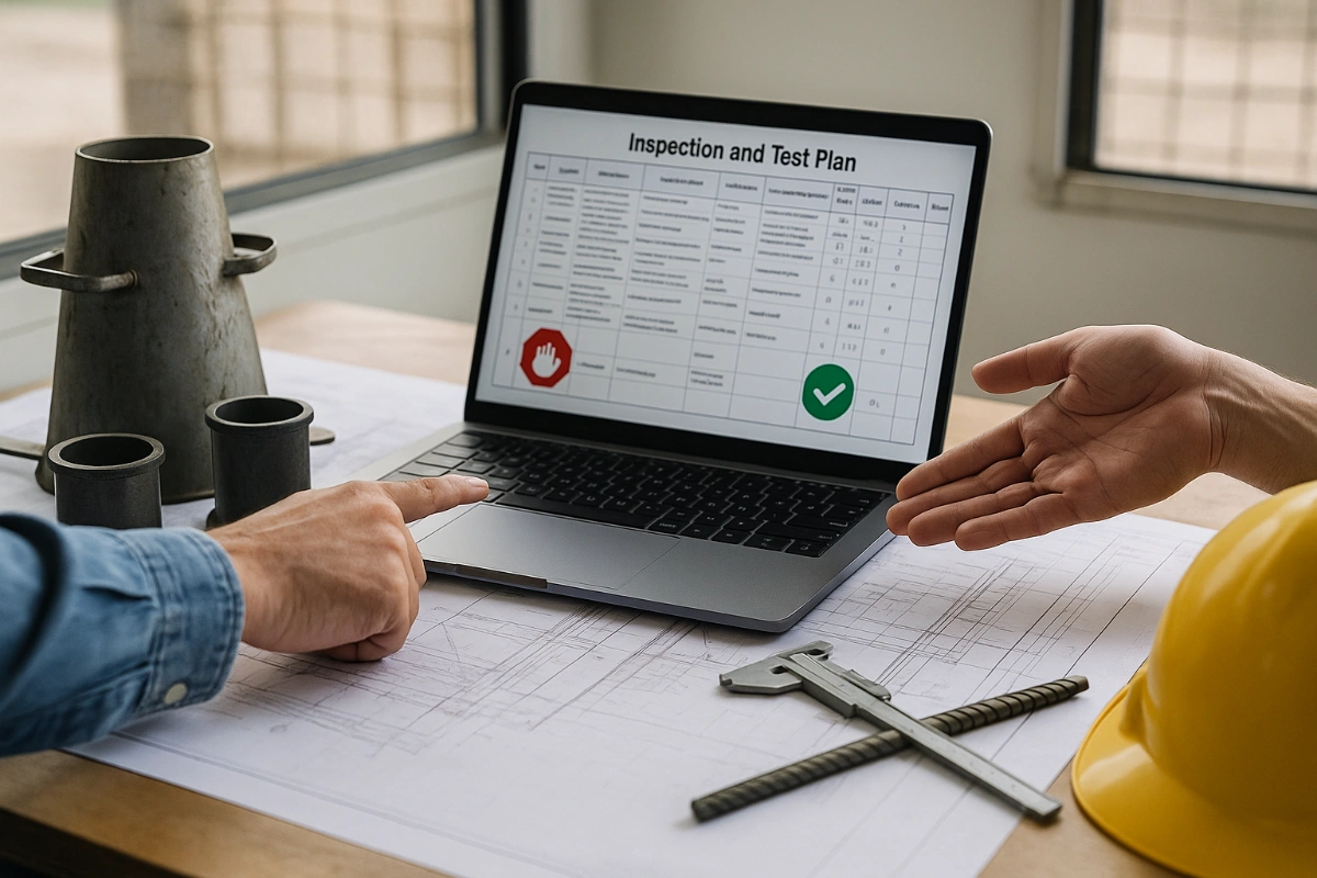
An Inspection and Test Plan (ITP) is available for Method Statement: Pneumatic Testing of Oil & Gas Piping Systems. The ITP defines the inspection activities, acceptance criteria, hold and witness points, responsible parties, and records required to verify the work described in this method statement.
View the Method Statement: Pneumatic Testing of Oil & Gas Piping Systems ITP →Frequently asked questions
Continue with related Quollnet resources connected to this method statement.